Chery Tiggo. Manual - part 308


  Index      Chery     Chery Tiggo - service repair manual 2009 year


Search            


Content   ..  306  307  308  309   ..


Chery Tiggo. Manual - part 308


4. Gear Hub and Hub of Synchronizer

• Assemble the gear bushing together with the

gear hub of synchronizer, and then inspect for
smooth operation without lockup.

• Inspect the front/rear of the interior surface of

the gear bushing for any damage.

• Inspect the synchronizer springs for any weak

springs or damage.

NOTE: If it is necessary to replace the gear
bushing and gear hub of the synchronizer,
they are only serviced as a complete set.

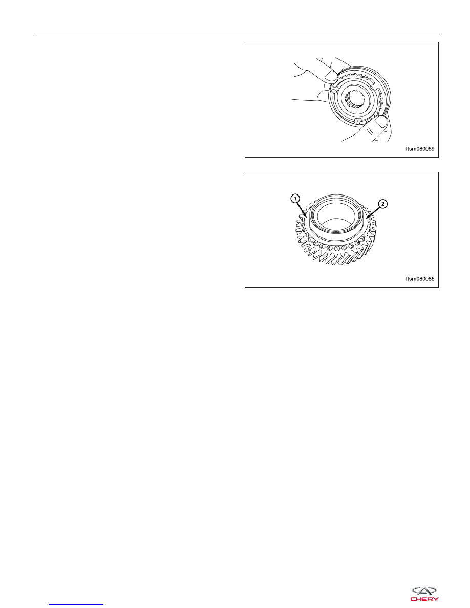
5. 3rd-4th Driven Gear

• Inspect the gear surface of the skew gear and

clutch gear (1) for any damage.

• Inspect the conical surface of the synchronizer

(2) for thickening, damage or wear.

• Inspect the internal diameter of the front/rear

surface of the gear.

MANUAL TRANSAXLE UNIT REPAIR

LTSM080059

LTSM080085


Output Shaft

Disassemble

1 - Outer Ring-1st-2nd Synchronization Ring

2 - Gear Hub Sleeve-1st-2nd Synchronizer

3 - Guide Block

4 - Spring-1st-2nd Gear And 5th-Reverse Gear Synchronizer

5 - Gear Hub-1st-2nd Gear

6 - Steel Ring-1st-2nd Synchronization Ring

7 - Inner Ring-1st-2nd Synchronization Ring

8 - 4th Driven Gear

9 - Gear Bushing-5th Gear

10 - Needle Bearing-Reverse Gear

11 - 5th Driven Gear Assembly

12 - Reverse Driven Gear Assembly

13 - Sleeve-Reverse Gear

14 - Synchronization Ring-3rd-4th Gear And 5th-Reverse
Gear

15 - Gear Hub Sleeve-5th-Reverse Gear

16 - Gear Hub-5th-Reverse Gear

17 - Snap Ring-3rd Driven Gear

18 - 3rd Driven Gear

19 - 2nd Driven Gear Assembly

20 - Needle Bearing-2nd Gear

21 - Sleeve-2nd Gear

22 - 1st Driven Gear Assembly

23 - Needle Bearing-1st Gear

24 - Sleeve-1st Gear

25 - Snap Ring-Output Shaft Front Bearing

26 - Output Shaft Front Bearing

27 - Output Shaft

28 - Output Shaft Rear Bearing

29 - Snap Ring-Output Shaft Rear Bearing

MANUAL TRANSAXLE UNIT REPAIR

LTSM080060

08


NOTE :
The following special tools are required to perform the repair procedure:
• MB-998801 - Bearing Remover

• MB-998812 - Installer Cap

• MB-998814 - Installer Connector (200 mm)

• MB-998813 - Installer (100)

• MB-998818 - Installer Connector (38 mm)

• MB-998819 - Installer Connector (40 mm)

• MB-998822 - Installer Connector (46 mm)

• MB-998825 - Installer Connector (52 mm)

1. Using special tool MB-998917 (2), disassemble the

output shaft rear bearing (1).

2. Disassemble the reverse gear sleeve (1).

Install special tool MB-998801 (2) on the reverse
driven gear, and then disassemble the sleeve.

3. Disassemble the 5th-reverse gear synchronizer

hub (1).
Install special tool MB-998801 (2) on the 4th driven
gear, and then disassemble the gear hub-5th-re-
verse gear.

MANUAL TRANSAXLE UNIT REPAIR

LTSM080061

LTSM080062

LTSM080063


4. Disassemble the 3rd driven gear (1).

Install special tool MB-998917 (2) on the 2nd
driven gear, and then disassemble the 3rd driven
gear.

5. Disassemble the sleeve-2nd gear (1).

Install special tool MB-998917 (2) on the 1st driven
gear, and then disassemble the sleeve-2nd gear.

6. Using special tool MB-998801 (2), disassemble the

sleeve-1st gear (1).

7. Using special tool MB-998917 (2), disassemble the

output shaft front bearing race (1).

MANUAL TRANSAXLE UNIT REPAIR

LTSM080064

LTSM080065

LTSM080066

LTSM080067

08


Content   ..  306  307  308  309   ..