Chery Tiggo. Manual - part 307


  Index      Chery     Chery Tiggo - service repair manual 2009 year


Search            


Content   ..  305  306  307  308   ..


Chery Tiggo. Manual - part 307


4. Install the synchronizer spring.

Install the synchronizer spring in the specified posi-
tion of the synchronizer ring, shown in the figure.

5. Install the gear hub-3rd-4th gear.

Install the gear hub-3rd-4th gear in the direction
shown in the figure.

CAUTION:
Ensure that the synchronizer ring is not locked when installing the gear hub.

6. Using special tools MB-998801 (4), MB-998812 (1),

MB-998813 (2) and MB-998825 (3), install the gear
bushing-3rd-4th gear.

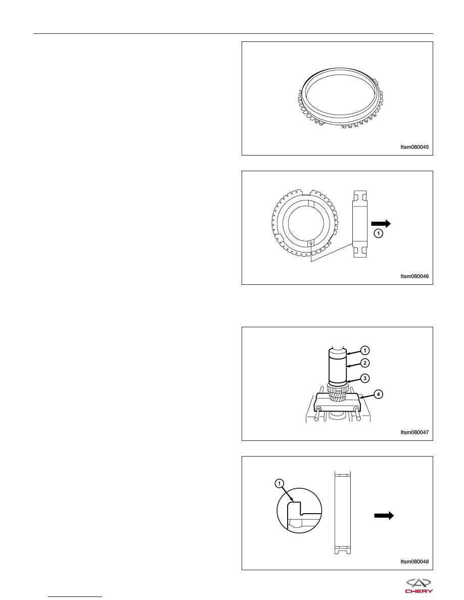
7. Install the hub sleeve in the direction shown in the

figure.

MANUAL TRANSAXLE UNIT REPAIR

LTSM080045

LTSM080046

LTSM080047

LTSM080048


8. Ensure that these two deep tooth spaces of gear

hub (1) & (2) are correctly aligned with the two
high racks of the gear hub during the installation of
gear bushing.

9. Using special tools MD-998801 (4), MD-998812

(1), MD-998813 (2), and MD-998824 (3), install the
sleeve-4th gear.

10. Using special tools MD-998801 (4), MD-998812

(1), MD-998813 (2), and MD-998824 (3), install the
5th driving gear.

11. Installation of transaxle housing assembly.

Select the thickness of the thrust plate (1) 5th driv-
ing gear to maintain the proper axial clearance of
input shaft 5th driving gear shaft.
(The Standard Value: 0.01 mm to 0.09 mm)

MANUAL TRANSAXLE UNIT REPAIR

LTSM080049

LTSM080050

LTSM080051

LTSM080052

08


12. Install the clip-5th driving gear thrust plate (1).

Ensure that the thrust plate doesn’t tilt when install-
ing the clip.

13. Using special tools MD-998801 (3), MD-998812 (1)

and MD-998818 (2), install the input shaft rear
bearing.

14. Install the snap ring.

Select the thickness of snap ring (1) to maintain
the proper axial clearance of input shaft rear bear-
ing.
(Standard Value: 0.01 mm to 0.12 mm)

MANUAL TRANSAXLE UNIT REPAIR

LTSM080053

LTSM080054

LTSM080055


Inspection

1. Input Shaft

• Inspect the external surface of the input shaft

and needle bearings (1) for any damage or
excessive wear.

• Inspect the input shaft spline for any damage

or excessive wear.

2. Needle Bearing

Inspect the input shaft and gears for smooth operation.

3. Synchronizer Ring

• Inspect the synchronizer rings for any damage

or signs of breakage in the surface of synchro-
nizer rings.

• Press synchronizer ring (1) 3rd-4th gear (2),

and then examine the clearance “A”. If the “A”
is less than the limit value, the synchronizer
ring and 3rd-4th gear should be replaced.(Limit
Value: 0.5 mm)

1 - Synchronizer Ring

2 - Gear

MANUAL TRANSAXLE UNIT REPAIR

LTSM080056

LTSM080057

LTSM080058

08


Content   ..  305  306  307  308   ..