Chery Tiggo. Manual - part 309


  Index      Chery     Chery Tiggo - service repair manual 2009 year


Search            


Content   ..  307  308  309  310   ..


Chery Tiggo. Manual - part 309


Assemble

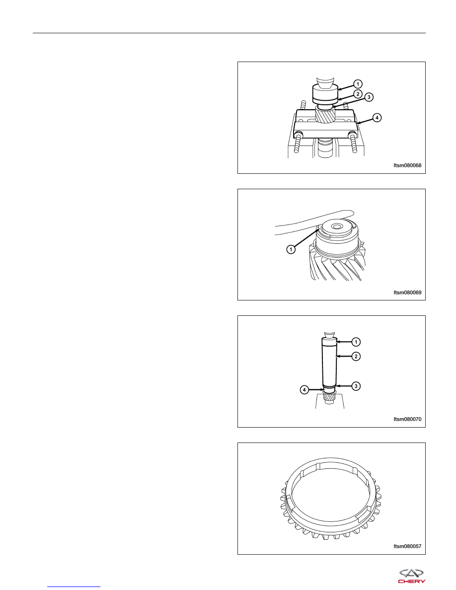
1. Using special tools MB-998801 (4), MB-998812 (1)

and MB-998818 (2), install the output shaft front
bearing race (3).

2. Install the snap ring-output shaft front bearing (1).

Select the snap ring and install it to maintain the
proper axial clearance of the output shaft front
bearing.
(Standard Value: 0.01 mm to 0.12 mm)

3. Using special tools MB-998812 (1), MB-998814 (2)

and MB-998825 (3), install the sleeve-1st gear (4).

4. Install the 1st-2nd gear synchronization ring.

Install the 1st-2nd gear synchronizer ring correctly
on the specified position of synchronizer ring
shown in the figure.

MANUAL TRANSAXLE UNIT REPAIR

LTSM080068

LTSM080069

LTSM080070

LTSM080057


5. Install the gear hub-1st-2nd gear.

Install the gear hub-1st-2nd gear in the position (1)
shown in the figure.

CAUTION:
Using special tools MD-998814 (1), MD-998815
(2) and MD-998825 (3), install the synchronizer
ring (4). Ensure that the synchronizer ring is
not locked when installing the gear hub.

6. Install the gear hub sleeve-1st-2nd gear synchro-

nizer.

• Install the gear bushing on the position (1)

shown in the figure.

• Ensure that the two deep tooth spaces of the

gear hub (1) are correctly aligned with the two
high racks of the gear hub during the installa-
tion of gear bushing.

MANUAL TRANSAXLE UNIT REPAIR

LTSM080079

LTSM080071

LTSM080048

LTSM080049

08


7. Install the synchronizer Ring.

8. Using special tools MB-998812 (1), MB-998814 (2)

and MB-998822 (3), install the sleeve-2nd gear (4).

9. Using special tools MB-998812 (1), MB-998814 (2)

and MB-998822 (3), install the 3rd driven gear (4).

10. Install the snap ring-3rd driven gear (1). Install the

snap ring to maintain the proper axial clearance of
the output shaft 3rd driven gear.
(Standard Value: -0.01 mm to 0.09 mm)

MANUAL TRANSAXLE UNIT REPAIR

LTSM080073

LTSM080074

LTSM080075

LTSM080076


11. Using special tools MB-998812 (1), MB-998813 (2)

and MB-998819 (3), install the 4th driven gear (4).

12. Using special tools MB-998812 (1), MB-998813 (2)

and MB-998819 (3), install the sleeve-5th gear (4).

13. Install the gear hub-5th-reverse gear.

Install the gear hub-5th-reverse gear in the position
(1) shown in the figure.

CAUTION:
Using special tools MD-998812 (1), MD-998813
(2) and MD-998819 (3), install the synchronizer
ring (4). Ensure that the synchronizer ring is
not locked when installing the gear hub-5th-re-
verse gear.

MANUAL TRANSAXLE UNIT REPAIR

LTSM080077

LTSM080078

LTSM080079

LTSM080080

08


Content   ..  307  308  309  310   ..