Chery Tiggo. Manual - part 296


  Index      Chery     Chery Tiggo - service repair manual 2009 year


Search            


Content   ..  294  295  296  297   ..


Chery Tiggo. Manual - part 296


2.

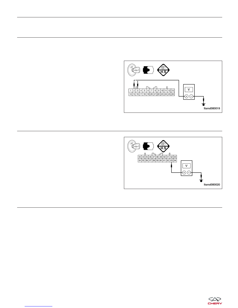
CHECK A/T RELAY SUPPLY VOLTAGE

• Turn ignition switch ON and then OFF.

• Check voltage between TCM terminals 2, 3 and ground.

• Turn ignition switch ON, battery voltage will exist.

• After turning ignition switch OFF, battery voltage will exist for a few seconds, then drop to approximately 0 V.

Is the check result normal?

Yes

>>

Go to step 8.

No

>>

Go to the next step.

3.

CHECK A/T RELAY CONTROL VOLTAGE

• Turn ignition switch on.

• Check voltage between ECM terminal 63 and

ground.

• Voltage should be more than 12 V.

Is the check result normal?

Yes

>>

Go to the next step.

No

>>

Go to step 8.

4.

CHECK A/T RELAY CONTROL VOLTAGE CIRCUIT

• Disconnect TCM harness connector.

• Disconnect front fuse and relay box harness connector H.

• Check harness continuity between TCM terminal 63 and front fuse and relay box terminal H6.

• Check harness continuity between front fuse and relay box terminal H10 and front fuse and ground.

• Check harness connector A-102, E-105, terminal 11.

• Continuity should exist.

• Check the harness for short to power or short to ground.

Is the check result normal?

Yes

>>

Go to the next step.

No

>>

Repair or replace the circuit for an open or short to ground or short to power in harness or connec-

tors.

DIAGNOSIS & TESTING

LTSMD080019

LTSMD080020


5.

CHECK A/T RELAY SUPPLY CIRCUIT

• Check harness continuity between TCM terminal 2, 3 and front fuse and relay box terminal H9.

• Check for harness continuity between front fuse and relay box terminal H8 and G15.

• Check harness connector A-102, E-105, terminal 1.

• Continuity should exist.

• Check the harness for short to ground.

Is the check result normal?

Yes

>>

Go to the next step.

No

>>

Repair or replace the circuit for an open or short to ground in harness or connectors.

6.

CHECK FUSE

• Disconnect Fuse 10 (30A) fuse from the front fuse and relay box.

• Check fuse 10 (30A).

Is the check result normal?

Yes

>>

Go to the next step.

No

>>

Replace fuse 10 (30A).

7.

CHECK FRONT FUSE AND RELAY BOX

• Check front fuse and relay box.

Is the check result normal?

Yes

>>

Go to the next step.

No

>>

Replace front fuse and relay box.

8.

CHECK DTC

• With the X-431 scan tool, read TCM DTCs.

• Refer to ⬙DTC Confirmation Procedure⬙.

Is DTC 54 still present?

Yes

>>

Replace the TCM.

No

>>

The system is now operating properly.
Reassemble the vehicle and road test to verify the customers complaint is repaired.

DIAGNOSIS & TESTING

08


ON-VEHICLE SERVICE

F4A4 Automatic Transaxle Assembly

Removal & Installation

1. Raise and support the vehicle.

2. Disconnect the negative battery cable.

3. Remove the battery and battery tray (See Battery Removal & Installation in Section 05 Starting & Charging).

4. Remove the air cleaner and air duct assembly.

5. Drain the cooling system (See Cooling System Draining Procedure in Section 06 Cooling System).

6. Remove the base mounting bolts (1) of the air

cleaner housing assembly.

7. Disconnect and remove the electrical connectors

for the following components:

• Output shaft sensor (1)

• Input shaft sensor (2)

• Electromagnetic valve switch connector (3)

• Gear switch connector (5)

8. Disconnect the transaxle fluid lines (6) using a suit-

able tool.

9. Remove the shift cable (4) from the transaxle

assembly.

10. Remove the starter motor (See Starter Removal & Installation in Section 05 Starting & Charging).

BESM080038

LTSM080153


11. Remove the bolts (1) attaching the drive plate to

the torque converter.
(Tighten: Drive plate bolts to 75 N·m)

12. Support the engine using an engine support fixture or suitable jack.

13. Remove the engine to transaxle upper bolts and remove the bracket.

(Tighten: Engine to transaxle upper bolts to 80 N·m)

14. Remove transaxle mount nuts (2) and the transaxle

mount bracket bolts (1).
(Tighten: Transaxle mount nuts to 120 N·m)

15. Raise the vehicle.

16. Remove the drain plug (1) and drain the transaxle

fluid.

ON-VEHICLE SERVICE

BESM080058

LTSM020156

LTSM080190

08


Content   ..  294  295  296  297   ..