Chery Tiggo. Manual - part 295


  Index      Chery     Chery Tiggo - service repair manual 2009 year


Search            


Content   ..  293  294  295  296   ..


Chery Tiggo. Manual - part 295


MEASURE STATUS

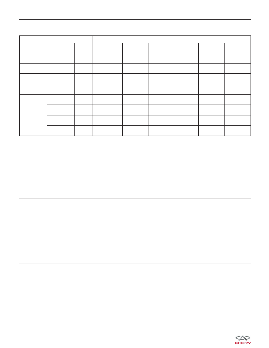
STANDARD FLUID PRESSURE KPA (PSI)

GEAR LEVER

POSITION

GEAR

POSITION

ENGINE

SPEED

(RPM)

DECELERATION

CLUTCH

PRESSURE

REVERSE

GEAR

CLUTCH

PRESSURE

OVERDRIVE

CLUTCH

PRESSURE

LOW/

REVERSE

GEAR

CLUTCH

PRESSURE

SECONDARY

BRAKE

PRESSURE

TORQUE

CONVERTER

PRESSURE

P

-

2,500

-

-

-

310 - 390

(45-56)

-

250 - 390 (36

- 56)

R

Reverse Gear

2,500

-

1,270 - 1,770

-

1,270 - 1,770

-

500 - 700 (73

- 101)

N

Neutral Gear

2,500

-

-

-

310 - 390 (45

- 56)

-

250 - 390 (36

- 56)

D

Gear 1

2,500

1,010 - 1,050

(146 - 152)

-

-

1,010 - 1,050

(146 - 152)

-

500 - 700 (73

- 101)

Gear 2

2,500

-

-

-

-

1,010 - 1,050

(146 - 152)

500 - 700 (73

- 101)

Gear 3

2,500

590 - 690 (85 -

100)

-

590 - 690

(85 - 100)

-

-

450 - 650 (65

- 94)

Gear 4

2,500

-

-

590 - 690

(85 - 100)

-

590 - 690 (85

- 100)

450 - 650 (65

- 94)

• In accordance with the shown status of standard fluid pressure measurement table, measure the fluid pressure

of each measurement port. The measurement of each port should be within the standard range.

• If some measurement values is beyond the standard range, please refer to the fluid pressure measurement and

diagnosis table for causes.

Is the check result normal?

Yes

>>

Go to step 5 for disc or plate abrasion.

No

>>

Go to the next step.

3.

CHECK VALVE BODY ASSEMBLY AND FLUID PUMP AND PIPELINE

• Turn the ignition switch off.

• Disassemble and repair F4A4 automatic transaxle assembly (See Automatic Transaxle Removal & Installation in

Section 08 Transaxle & Transfer Case).

• Check valve body and fluid pump and pipeline.

Is the check result normal?

Yes

>>

Go to the next step.

No

>>

Replace damaged components and low speed clutch and reverse gear clutch for low pressure burned.

4.

COMPRESSED AIR TEST

• Check low speed clutch system: Low speed clutch piston should be active and maintain pressure when com-

pressed air is applied to the fluid hole.

• Check reverse gear clutch system: Reverse gear clutch piston should be active and maintain pressure when

compressed air is applied to the fluid hole.

Is the check result normal?

Yes

>>

Go to the next step for disc or plate abrasion.

No

>>

Replace damaged components and low speed clutch and reverse gear clutch for low pressure burned.

DIAGNOSIS & TESTING


5.

CHECK LOW SPEED CLUTCH SYSTEM

• Stop vehicle and turn ignition switch off.

• Disassemble and repair F4A4 automatic transaxle assembly (See Automatic Transaxle Removal & Installation in

Section 08 Transaxle & Transfer Case).

• Check low speed clutch system:

− Check low speed clutch plate
− Check low speed clutch disc
− Snap ring
− Clutch reaction disc
− D-Ring
− Spring retainer
− Low speed clutch drum
− Low speed clutch piston

Is the check result normal?

Yes

>>

Go to the next step.

No

>>

Replace the damaged components.

6.

CHECK REVERSE GEAR CLUTCH SYSTEM

• Check reverse gear clutch system:

− Reverse gear clutch plate
− Reverse gear clutch disc
− Central support
− Snap ring
− Clutch reaction disc
− Spring retainer
− Reverse gear clutch piston

Is the check result normal?

Yes

>>

Go to the next step.

No

>>

Replace the damaged components.

7.

CHECK DTC

• Assemble all disassembled components.

• Install the transaxle assembly (See Automatic Transaxle Removal & Installation in Section 08 Transaxle &

Transfer Case).

• Fill the transaxle with new ATF:

− Fill the ATF from the fill tube.
− Reinstall the hose connector disassembled in step 1 and reinstall the dipstick (clean the dipstick before

installing).

− Shift the gear selector lever to each gear position and then shift to gear “N”.
− Drive the vehicle until the ATF reaches operating temperature (70° - 80°C) and re-check the fluid level. The

fluid level must be within the HOT range of dipstick.

− Reinstall the dipstick into the transaxle.

• With the X-431 scan tool, read TCM DTCs.

• Refer to ⬙DTC Confirmation Procedure⬙.

Is DTC 46 present?

Yes

>>

Replace the TCM.

No

>>

The system is now operating properly.

DIAGNOSIS & TESTING

08


54 - Electrical Relay Open Circuit

DIAGNOSIS & TESTING

LTSMW080003T


On Board Diagnostic Logic
• Self-diagnosis detection logic.

DTC NO.

DTC DEFINITION

DTC DETECTION

CONDITION

DTC SET

CONDITION

POSSIBLE CAUSES

54

Electrical relay open

circuit

Ignition switch on

• The Transaxle
Control Module
(TCM) will set this
DTC when the TCM
detected that the
A/T control voltage
is below 7 V.

• If the DTC was
set, then the A/T will
be locked in 3rd
gear (D gear) or
shifted to low gear
when in sports
mode.

• A/T control relay

• Harness or
connectors (The
sensor circuit is open
or shorted)

• TCM

DTC Confirmation Procedure:

Before performing the following procedure, confirm that battery voltage is more than 12 V.

• Connect the X-431 scan tool to the Data Link Connector (DLC) - use the most current software available.

• After connection, press POWER key to start X-431.

• Turn the ignition switch on.

• With the scan tool, view and erase stored DTCs in the TCM.

• Start engine and warm it to normal operating temperature.

• With the scan tool, select view DTC and data stream.

• If the DTC is detected, the DTC condition is current. Go to Diagnostic Procedure - Step 1.

• If the DTC is not detected, the DTC condition is intermittent (See Diagnostic Help and Intermittent DTC Trou-

bleshooting in Section 08 Transaxle & Transfer Case for more information).

NOTE :
While performing electrical diagnosis & testing, always refer to the electrical schematics for specific circuit
and component information.

Diagnostic Procedure

1.

CHECK GROUND CONNECTION

• Turn ignition switch off.

• Loosen and retighten ground screws on the body (See Ground Inspection in Section 12 Brakes).

• Inspect the ground connection C-201 mounting position (See Vehicle Wiring Harness Layout - Main Harness in

Section 16 Wiring).

Are the ground connections OK?

Yes

>>

Go to the next step.

No

>>

Repair or replace the ground connections.

DIAGNOSIS & TESTING

08


Content   ..  293  294  295  296   ..