Chery Tiggo. Manual - part 154


  Index      Chery     Chery Tiggo - service repair manual 2009 year


Search            


Content   ..  152  153  154  155   ..


Chery Tiggo. Manual - part 154


Check reference values between ECM terminals and ground under the following conditions:
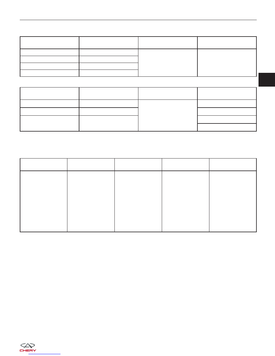
ECM TERMINAL NO.

ITEM

CONDITION

DATA (AVERAGE DC

VOLTAGE)

6

Injector 2

• Engine is running

• Warm-up condition

• Idle

• Accelerate suddenly

Voltage: 11 - 14 V

7

Injector 3

27

Injector 1

47

Injector 4

ECM TERMINAL NO.

ITEM

CONDITION

DATA (AVERAGE DC

VOLTAGE)

17

Sensor (GND)

• Engine is running

• Warm-up condition:
78°C

• Idle: 795 RPM

• IAT: 36°C

• IAT signal: 1.88 V

0 V

33

Regulated sensor supply 1

Approximately 5 V

37

Air flow sensor

Approximately 322 kg/h

Approximately 1.39 V

On Board Diagnostic Logic
• Self-diagnosis detection logic.

DTC NO.

DTC DEFINITION

DTC DETECTION

CONDITION

DTC SET

CONDITION

POSSIBLE CAUSE

P0171

Fuel trim system too

lean

Engine is running

The amount of
mixture ratio
compensation is too
large (The mixture
ratio is too lean).

• Intake air leaks

• Air flow sensor

• Fuel injector

• Exhaust gas leaks

• Incorrect fuel
pressure

• lack of fuel

• Incorrect PCV
hose connection

• Upstream O

2

sensor

• ECM

DTC Confirmation Procedure:

Before performing the following procedure, confirm that battery voltage is more than 12 V.

• Turn ignition switch off.

• Connect the X-431 scan tool to the Data Link Connector (DLC) - use the most current software available.

• Turn ignition switch on.

• With the scan tool, record and erase stored DTCs in the ECM.

• Start engine and warm it to normal operating temperature, then select view DTC and data stream.

• If the DTC is detected, the DTC condition is current. Go to Diagnostic Procedure - Step 1.

• If the DTC is not detected, the DTC condition is intermittent (See Diagnostic Help and Intermittent DTC Trou-

bleshooting in Section 03 Electronic Engine Controls for more information.

NOTE :
While performing electrical diagnosis & testing, always refer to the electrical schematics for specific circuit
and component information.

DIAGNOSIS & TESTING

03


Diagnostic Procedure

1.

CHECK EXHAUST GAS LEAK

• Start engine and run it at idle.

• Listen for exhaust gas leak before the three way catalyst.

Is the check result normal?

Yes

>>

Go to the next step.

No

>>

Repair or replace.

2.

CHECK FOR INTAKE AIR LEAK

• Turn ignition switch on.

• Listen for intake air leak after the air flow sensor.

• Check PCV hose connector.

Is the check result normal?

Yes

>>

Go to the next step.

No

>>

Repair or replace.

3.

CHECK ECM CONTROL SIGNAL IN DATA STREAM

• With the X-431, select view data stream.

MONITOR ITEM

CONDITION

DATA

Injector pulse

• Engine: warm up

• Shift: P or N

• Air conditioning: off

• No load

Idle

Approximately 2.5 ms

Is the check result normal?

Yes

>>

Go to step 7.

No

>>

Go to the next step.

4.

CHECK UPSTREAM O

2

SENSOR ELECTRICAL CONNECTOR

• Turn ignition switch off.

• Disconnect the upstream O

2

sensor (1) electrical

connector.

• Inspect the electrical connector for damage.

Is the electrical connector OK?

Yes

>>

Go to the next step.

No

>>

Repair or replace the electrical connector

as necessary.

DIAGNOSIS & TESTING

BESM030017


5.

CHECK UPSTREAM O

2

SENSOR SIGNAL CIRCUIT

• Disconnect ECM harness connector.

• Check harness continuity between the following terminals.

UPSTREAM O

2

SENSOR

ECM TERMINAL

O

2

SENSOR TERMINAL

O

2

sensor 1

36

3

18

4

• Continuity should exist.

• Also check harness for short to ground.

Is the check result normal?

Yes

>>

Go to the next step.

No

>>

Repair or replace circuit for an open or short to ground in harness or connectors.

6.

CHECK AIR FLOW SENSOR SIGNAL

• Check air flow in data stream.

TERMINAL NO.

ITEM

CONDITION

DATA (AVERAGE DC

VOLTAGE)

37

Air flow sensor

• Engine is running

• ECT: 78°C

• Idle: 795 RPM

• IAT: 36°C

• IAT signal: 1.88 V

Approximately 322 kg/h

Approximately 1.39 V

Is the check result normal?

Yes

>>

Go to the next step.

No

>>

Check connectors for rusted terminals or loose connectors in the air flow sensor circuit or ground.

DIAGNOSIS & TESTING

03


7.

CHECK FUEL PRESSURE

• Release fuel pressure to zero.

• Install fuel pressure gauge (2) and check fuel

pressure.

• Observe the following fuel pressures when testing (See Fuel Pressure Test in Section 04 Fuel Delivery).

FUEL PRESSURES

Key On

400 kPa (4.0 bar)

Key Off

380 kPa (3.8 bar) in 10 minutes

Engine Idle                                                            400 kPa (4.0 bar )

 - 420 kPa (4.2 bar)

Is the check result normal?

Yes

>>

Go to step 9.

No

>>

Go to the next step.

8.

DETECT MALFUNCTIONING PART

• Check the following:

− Fuel pump and circuit.
− Fuel pressure regulator.
− Fuel lines.
− Fuel filter for clogging.

Is the check result normal?

Yes

>>

If with the X-431, go to the next step.
If without the X-431, go to step 10.

No

>>

Repair or Replace malfunctioning part.

DIAGNOSIS & TESTING

BESM030020


Content   ..  152  153  154  155   ..