Chery Tiggo. Manual - part 118
8.
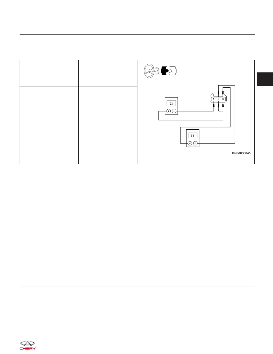
CHECK CMP SENSOR
• Check resistance as table shown.
• Remove the sensor.
• Visually check and clean the sensor for chipping.
TERMINAL NO.
RESISTANCE
⍀ (25°C)
1 & 2
Except 0 or
⬁
1 & 3
2 & 3
Is the check result normal?
Yes
>>
Replace the CMP sensor with a known good CMP sensor.
Monitor the CMP sensor signal on the KES-200 screen.
− If the CMP sensor signals were normal, the system is OK.
− If the CMP sensor signals were still irregular or missing, go to Step 9.
No
>>
Replace CMP sensor.
9.
CHECK INSTALLED CLEARANCE
• Check the installed clearance (See CMP Sensor Removal & Installation in Section 03 Electronic Engine Con-
trols).
• 0.8 - 1.2 mm should exist.
Is the check result normal?
Yes
>>
Go to the next step.
No
>>
Reinstall CMP sensor.
10.
CHECK CAMSHAFT
• Check the following:
− Accumulation of debris to the signal plate of camshaft rear end
− Chipping signal plate of camshaft rear end
Is the check result normal?
Yes
>>
Go to the next step.
No
>>
Remove debris and clean the signal plate of camshaft rear end or replace camshaft.
DIAGNOSIS & TESTING
03