Chery Tiggo. Manual - part 117


  Index      Chery     Chery Tiggo - service repair manual 2009 year


Search            


Content   ..  115  116  117  118   ..


Chery Tiggo. Manual - part 117


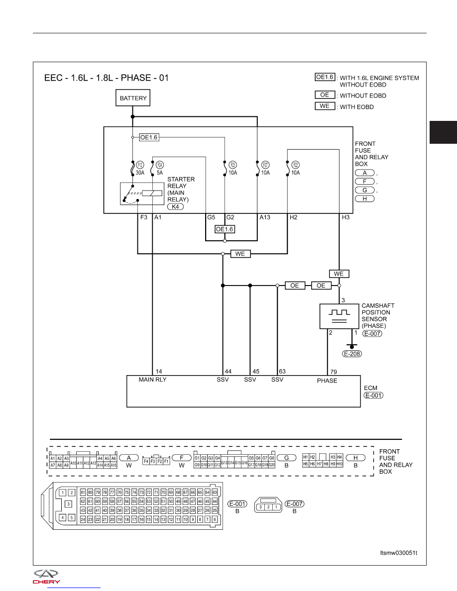
P0343 - Camshaft Position Sensor Circuit High Input

DIAGNOSIS & TESTING

LTSMW030051T

03


Check reference values between ECM terminals and ground under the following conditions:

ECM TERMINAL NO.

ITEM

CONDITION

VOLT (AVERAGE DC

VOLTAGE)

79

Camshaft Position (CMP)

sensor

• Ignition switch: ON

• Engine: Not cranking

11 V

On Board Diagnostic Logic
• Self-diagnosis detection logic.

DTC NO.

DTC DEFINITION

DTC DETECTION

CONDITION

DTC SET

CONDITION

POSSIBLE CAUSE

P0343

Camshaft Position

(CMP) sensor circuit

high input

Engine is running

ECM detected that

the input signal is

out of the

acceptable range.

• CMP sensor

• Camshaft

• Harness or
connectors

• ECM

DTC Confirmation Procedure:

Before performing the following procedure, confirm that battery voltage is more than 12 V.

• Turn ignition switch off.

• Connect the X-431 scan tool to the Data Link Connector (DLC) - use the most current software available.

• Turn ignition switch on.

• With the scan tool, record and erase stored DTCs in the ECM.

• Run engine for a while then select view DTC.

• If DTC is detected, go to Diagnostic Procedure - Step 1.

• If the DTC is not detected, the DTC condition is intermittent (See Diagnosis & Testing Diagnostic Help in Sec-

tion 03 Electronic Engine Controls).

NOTE :
While performing electrical diagnosis & testing, always refer to the electrical schematics for specific circuit
and component information.

Diagnostic Procedure

1.

CHECK GROUND CONNECTIONS

• Turn ignition switch off.

• Loosen and retighten ground screws on the body (See Ground Inspection in Section 03 Electronic Engine Con-

trols).

• Inspect ground connections E-207 and E-208 mounting position (See Vehicle Wiring Harness Layout - Engine

Room Harness (With 1.6L/1.8L Engine) in Section 16 Wiring).

Are the ground connections OK?

Yes

>>

Go to the next step.

No

>>

Repair or replace ground harness or connections.

DIAGNOSIS & TESTING


2.

CHECK CAMSHAFT POSITION (CMP) SENSOR ELECTRICAL CONNECTOR

• Disconnect the CMP sensor (1) electrical connector.

• Inspect the electrical connector for damage.

Is the electrical connector OK?

Yes

>>

Go to the next step.

No

>>

Repair or replace the electrical connector

as necessary.

3.

CHECK THE CAMSHAFT POSITION SENSOR POWER SUPPLY CIRCUIT FOR AN OPEN AND SHORT

• Turn ignition switch on.

• Check CMP sensor supply voltage between sensor

connector E-007, terminal 3 and ground in the sen-
sor electrical connector.

• 12 V should exist.

Is the check result normal?

Yes

>>

Go to step 5.

No

>>

Go to the next step.

4.

DETECT MALFUNCTIONING PART

• Check harness for an open or short between EVAP canister control valve and fuse.

• Check the following:

Without EOBD (1.6L)

− Front fuse and relay box F3, A1, G2, G5
− Fuse 23, fuse 24, fuse 12

Without EOBD

− Front fuse and relay box F3, A1, A13, G2, G5
− Fuse 23, fuse 24, fuse 12, fuse 27

WITH EOBD

− Front fuse and relay box F3, A1, A13, G5, H2, H3
− Fuse 22, fuse 24, fuse 12, fuse 27

Is the check result normal?

Yes

>>

Go to the next step.

No

>>

Repair or replace the malfunctioning parts.

DIAGNOSIS & TESTING

VISMD030001

LTSMD030044

03


5.

CHECK THE CMP SENSOR GROUND CIRCUIT FOR AN OPEN OR SHORT

• Turn ignition switch off.

• Check harness continuity between CMP sensor terminal 1 and ground.

• Continuity should exist.

• Check harness for short to power.

Is the check result normal?

Yes

>>

Go to the next step.

No

>>

Repair or replace circuit for an open or short to power in harness or connectors.

6.

CHECK THE CMP SENSOR INPUT SIGNAL CIRCUIT FOR OPEN OR SHORT TO POWER

• Turn ignition switch on.

• Check voltage between CMP sensor terminal 2 and ground.

• 11 V should exist.

Is the check result normal?

Yes

>>

Go to the next step.

No

>>

Repair or replace open circuit or short to power in harness or connectors.
If circuit is normal, go to the next step.

7.

CHECK CMP SENSOR SIGNAL

• Connect CMP sensor connector.

• Check signal voltage between CMP sensor terminal 2 and ground when engine is running.

• Approximately 6 V square wave signal should exist.

ENGINE ANALYZER (KES-200)

CMP SENSOR SIGNAL

Is the CMP output signal normal?

Yes

>>

Go to step 10.

No

>>

Go to the next step.

DIAGNOSIS & TESTING


Content   ..  115  116  117  118   ..