Chery Tiggo. Manual - part 115


  Index      Chery     Chery Tiggo - service repair manual 2009 year


Search            


Content   ..  113  114  115  116   ..


Chery Tiggo. Manual - part 115


2.

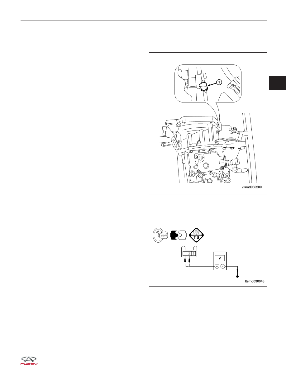
CHECK CRANKSHAFT POSITION (CKP) SENSOR ELECTRICAL CONNECTOR

• Disconnect the Injector (1) electrical connector.

• Inspect the electrical connector for damage.

Is the electrical connector OK?

Yes

>>

Go to the next step.

No

>>

Repair or replace the electrical connector

as necessary.

3.

CHECK CRANKSHAFT POSITION (CKP) SENSOR REFERENCE VOLTAGE

• Turn ignition switch on.

• Check CKP sensor supply voltage between sensor

connector E-006, terminal 1 and ground, terminal 2
and ground in the sensor electrical connector.

• 3 V should exist.

Is the check result normal?

Yes

>>

Go to step 5.

No

>>

Go to the next step.

DIAGNOSIS & TESTING

VISMD030200

LTSMD030048

03


4.

DETECT MALFUNCTIONING PART

• Check harness for an open or short between CKP sensor and ECM.

Is the check result normal?

Yes

>>

Replace the ECM.

NOTE : The Immobilizer control module must be matched to the new ECM (See ECM Removal & Instal-

lation in Section 03 Electronic Engine Controls).

No

>>

Repair circuit for open or short in harness or connectors.

5.

CHECK CKP SENSOR SIGNAL WAVE PATTERN

• Connect ECM connector.

• Connect CKP sensor connector.

• Check sensor output signal when engine is running.

ENGINE ANALYZER (KES-200)

CKP SENSOR SIGNAL

Is the CKP sensor output signal normal?

Yes

>>

Go to step 9.

No

>>

Go to the next step.

DIAGNOSIS & TESTING


6.

CHECK CKP SENSOR

• Check resistance as table shown.

• Remove the sensor.

• Visually check the sensor for chipping.

TERMINAL NO.

RESISTANCE

⍀ (25°C)

1 & 2

Approximately 860

Is the check result normal?

Yes

>>

Replace the CKP sensor with a known good CKP sensor.
Monitor the CKP sensor signal on the KES-200 screen.
− If the CKP sensor signals were normal, the system is OK.
− If the CKP sensor signals were still irregular or missing, go to step 7.

No

>>

Replace or clear CKP sensor.

7.

CHECK INSTALLED CLEARANCE

• Check the installed clearance (See Crankshaft Position (CKP) Sensor Removal & Installation in Section 08

Transaxle & Transfer Case).

• 0.8 - 1.2 mm should exist.

Is the check result normal?

Yes

>>

Go to the next step.

No

>>

Reinstall CKP sensor.

8.

CHECK GEAR TOOTH

• Visually check for chipping signal plate gear tooth.

Is the check result normal?

Yes

>>

Go to the next step.

No

>>

Replace the signal plate

DIAGNOSIS & TESTING

03


9.

CHECK DTC

• With the X-431 scan tool, read ECM DTCs.

• Refer to ⬙DTC Confirmation Procedure⬙.

Is DTC P0321 still present?

Yes

>>

Replace the ECM.

NOTE : The Immobilizer control module must be matched to the new ECM (See ECM Removal & Instal-

lation in Section 03 Electronic Engine Controls).

No

>>

The system is now operating properly.
Reassemble the vehicle and road test to verify the customers complaint is repaired.

DIAGNOSIS & TESTING


Content   ..  113  114  115  116   ..