Chery Tiggo. Manual - part 114


  Index      Chery     Chery Tiggo - service repair manual 2009 year


Search            


Content   ..  112  113  114  115   ..


Chery Tiggo. Manual - part 114


9.

DETECT MALFUNCTIONING PART

• Turn ignition switch off.

• Disconnect ECM harness connector.

• Check the injector control circuits for short to power supply circuits.

• Check the following.

• Voltage should not exist.

INJECTOR NO.

POWER SUPPLY CIRCUIT

INJECTOR TERMINAL

1

Power supply circuit

2

2

2

3

2

4

2

Is the check result normal?

Yes

>>

Go to the next step.

No

>>

Repair circuit for an open or short in harness or connectors.
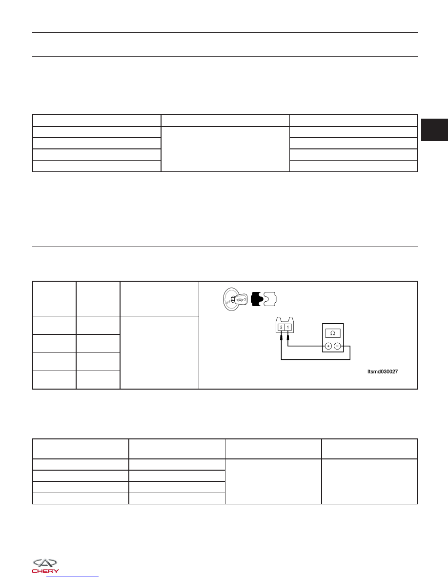
10.

CHECK INJECTOR RESISTANCE

• Check resistance as table shown.

• Check the fuel injector resistance as shown in the following:

INJECTOR

NO.

INJECTOR

TERMINAL

RESISTANCE

(APPROXIMATELY)

⍀ (20°C)

1

1 & 2

16

2

1 & 2

3

1 & 2

4

1 & 2

• Check signal output.

• Connect ECM connector.

• Connect injector connectors.

• Check the fuel injector voltage as shown in the following:

TERMINAL NO.

ITEM

CONDITION

DATA (AVERAGE DC

VOLTAGE)

6

Injector 2

• Engine is running

• Warm-up condition

• Idle

• Accelerate suddenly

Voltage: 11 - 14 V

7

Injector 3

27

Injector 1

47

Injector 4

Is the check result normal?

Yes

>>

Go to the next step.

No

>>

Replace injector.

DIAGNOSIS & TESTING

03


11.

CHECK DTC

• With the X-431 scan tool, read ECM DTCs.

• See ⬙DTC Confirmation Procedure⬙.

Is DTC P0262, P0265, P0268 or P0271 still present?

Yes

>>

Replace the ECM.

NOTE : The Immobilizer control module must be matched to the new ECM (See ECM Removal & Instal-

lation in Section 03 Electronic Engine Controls).

No

>>

The system is now operating properly.
Reassemble the vehicle and road test to verify the customers complaint is repaired.

DIAGNOSIS & TESTING


P0321 - Distributor Engine Speed In Phase Circuit Performance

DIAGNOSIS & TESTING

LTSMW030046T

03


Check reference values between ECM terminals and ground under the following conditions:

ECM TERMINAL NO.

ITEM

CONDITION

DATA (AVERAGE DC

VOLTAGE)

15

Crankshaft Position (CKP)

sensor

• Ignition switch: ON

• Engine: Not cranking

3 V

34

On Board Diagnostic Logic
• Self-diagnosis detection logic.

DTC NO.

DTC DEFINITION

DTC DETECTION

CONDITION

DTC SET

CONDITION

POSSIBLE CAUSE

P0321

Distributor engine

speed in phase

circuit performance

Engine is running

ECM detected that

the input signal is

out of the

acceptable range.

• CKP sensor

• Crankshaft signal
plate

• Harness or
connectors

• ECM

DTC Confirmation Procedure:

Before performing the following procedure, confirm that battery voltage is more than 12 V.

• Turn ignition switch off.

• Connect the X-431 scan tool to the Data Link Connector (DLC) - use the most current software available.

• Turn ignition switch on.

• With the scan tool, record and erase stored DTCs in the ECM.

• Crank engine for a few seconds and run it for a few seconds then select view DTC.

• If DTC is detected, go to Diagnostic Procedure - Step 1.

• If the DTC is not detected, the DTC condition is intermittent (See Diagnosis & Testing Diagnostic Help in Sec-

tion 03 Electronic Engine Controls).

NOTE :
While performing electrical diagnosis & testing, always refer to the electrical schematics for specific circuit
and component information.

Diagnostic Procedure

1.

CHECK GROUND CONNECTIONS

• Turn ignition switch off.

• Loosen and retighten ground screws on the body (See Ground Inspection in Section 03 Electronic Engine Con-

trols).

• Inspect ground connections E-207 and E-208 mounting position (See Vehicle Wiring Harness Layout - Engine

Room Harness (With 1.6L/1.8L Engine) in Section 16 Wiring).

Are the ground connections OK?

Yes

>>

Go to the next step.

No

>>

Repair or replace ground harness or connections.

DIAGNOSIS & TESTING


Content   ..  112  113  114  115   ..