Chery Tiggo. Manual - part 119


  Index      Chery     Chery Tiggo - service repair manual 2009 year


Search            


Content   ..  117  118  119  120   ..


Chery Tiggo. Manual - part 119


3.

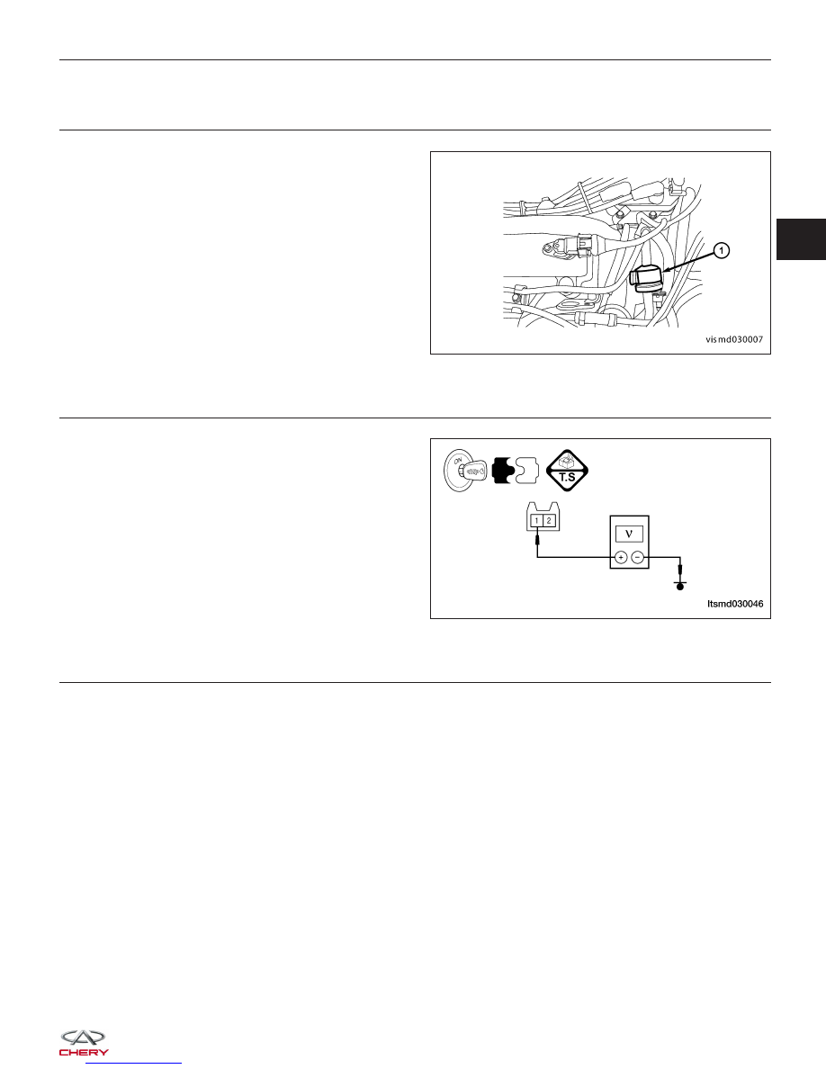
CHECK EVAP CANISTER CONTROL VALVE ELECTRICAL CONNECTOR

• Disconnect the EVAP canister control valve (1)

electrical connector.

• Inspect the electrical connector for damage.

Is the electrical connector OK?

Yes

>>

Go to the next step.

No

>>

Repair or replace the electrical connector

as necessary.

4.

CHECK EVAP CANISTER CONTROL VALVE POWER SUPPLY CIRCUIT

• Turn ignition switch on.

• Check supply voltage between EVAP canister con-

trol valve terminal 1 and ground.

• 12 V should exist.

Is the check result normal?

Yes

>>

Go to step 6.

No

>>

Go to the next step.

5.

DETECT MALFUNCTIONING PART

• Check harness for an open or short between EVAP canister control valve and fuse.

• Check the following:

Without EOBD (1.6L)

− Front fuse and relay box F3, A1, G2, G5
− Fuse 23, fuse 24, fuse 12

Without EOBD

− Front fuse and relay box F3, A1, A13, G2, G5
− Fuse 23, fuse 24, fuse 12, fuse 27

With EOBD

− Front fuse and relay box F3, A1, A13, G5, H2, H3
− Fuse 22, fuse 24, fuse 12, fuse 27

Is the check result normal?

Yes

>>

Go to the next step.

No

>>

Repair or replace malfunctioning part.

DIAGNOSIS & TESTING

VISMD030007

LTSMD030046

03


6.

CHECK EVAP CANISTER CONTROL VALVE CONTROL CIRCUIT FOR AN OPEN

• Check voltage between EVAP canister control valve terminal 2 and ground.

• Approximately 3.6 V should exist.

Is the check result normal?

Yes

>>

Go to the next step.

No

>>

Repair or replace open circuit in harness or connectors.
If harness is normal, go to the next step.

7.

CHECK EVAP CANISTER CONTROL VALVE

• Turn ignition switch off.

• Remove EVAP canister control valve.

• Check resistance as table shown.

EVAP CANISTER

CONTROL VALVE

TERMINAL NO.

RESISTANCE

(20°C)

1 & 2

Approximately 26

• Check air passage continuity and operation when apply 12 V current supply voltage between terminal 1 and 2.

• The check results should match specification.

Is the check result normal?

Yes

>>

Go to the next step.

No

>>

Replace EVAP canister control valve.

8.

CHECK DTC

• With the X-431 scan tool, read ECM DTCs.

• Refer to ⬙DTC Confirmation Procedure⬙.

Is DTC P0444 still present?

Yes

>>

Replace the ECM.

NOTE : The Immobilizer control module must be matched to the new ECM (See ECM Removal & Instal-

lation in Section 03 Electronic Engine Controls).

No

>>

The system is now operating properly.
Reassemble the vehicle and road test to verify the customers complaint is repaired.

DIAGNOSIS & TESTING


P0506 - Idle Control System RPM Lower Than Expected

• Self-diagnosis detection logic.

DTC NO.

DTC DEFINITION

DTC DETECTION

CONDITION

DTC SET

CONDITION

POSSIBLE CAUSE

P0506

Idle control system

RPM lower than

expected

• Engine is running.

• With the engine
idling in drive, the
brake applied,
engine run time
below a calibrated
minimum value, and
no VSS, MAF/MAP,
ECT, TPS, ETC,
Crankshaft Position
sensor, fuel system,
or injector DTCs
present.

ECM detected that

the idle speed is

less than the

acceptable range.

• Electronic throttle
control actuator

• Intake air leak

• ECM

DTC Confirmation Procedure:

Before performing the following procedure, confirm that battery voltage is more than 12 V.

• Turn ignition switch off.

• Connect the X-431 scan tool to the Data Link Connector (DLC) - use the most current software available.

• Turn ignition switch on.

• With the scan tool, record and erase stored DTCs in the ECM.

• Start engine and warm it up to the normal operating temperature then select view DTC.

• If DTC is detected, go to Diagnostic Procedure - Step 1.

• If the DTC is not detected, the DTC condition is intermittent (See Diagnosis & Testing Diagnostic Help in Sec-

tion 03 Electronic Engine Controls).

NOTE :
If DTC P0506 is displayed with other DTCs, perform this diagnostic procedure before other DTCs.

NOTE :
While performing electrical diagnosis & testing, always refer to the electrical schematics for specific circuit
and component information.

DIAGNOSIS & TESTING

03


Diagnostic Procedure

1.

CHECK INTAKE AIR LEAK

• Start engine and let it idle.

• Listen for an intake air leak after the mass air flow sensor.

Is the check result normal?

Yes

>>

Go to the next step.

No

>>

Discover air leak location and repair.

2.

CHECK THE ELECTRIC THROTTLE CONTROL ACTUATOR

• Check the electronic throttle open degree.

• Check the electronic throttle clearance.

Is the check result normal?

Yes

>>

Go to the next step.

No

>>

Clean or replace as necessary.

3.

CHECK DTC

• With the X-431 scan tool, read ECM DTCs.

• Refer to ⬙DTC Confirmation Procedure⬙.

Is DTC P0506 still present?

Yes

>>

Replace the ECM.

NOTE : The Immobilizer control module must be matched to the new ECM (See ECM Removal & Instal-

lation in Section 03 Electronic Engine Controls).

No

>>

The system is now operating properly.
Reassemble the vehicle and road test to verify the customers complaint is repaired.

DIAGNOSIS & TESTING


Content   ..  117  118  119  120   ..