Index Chery Chery Tiggo - service repair manual 2009 year
Search
Content .. 91 92 93 94 ..
Chery Tiggo. Manual - part 93
DIAGNOSIS & TESTING
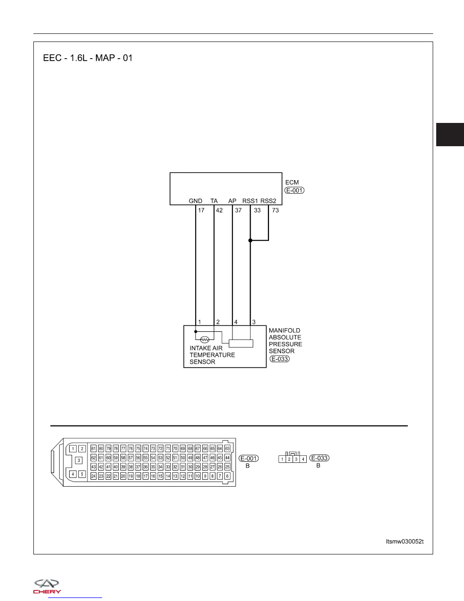
LTSMW030052T
03