Chery Tiggo. Manual - part 91


  Index      Chery     Chery Tiggo - service repair manual 2009 year


Search            


Content   ..  89  90  91  92   ..


Chery Tiggo. Manual - part 91


7.

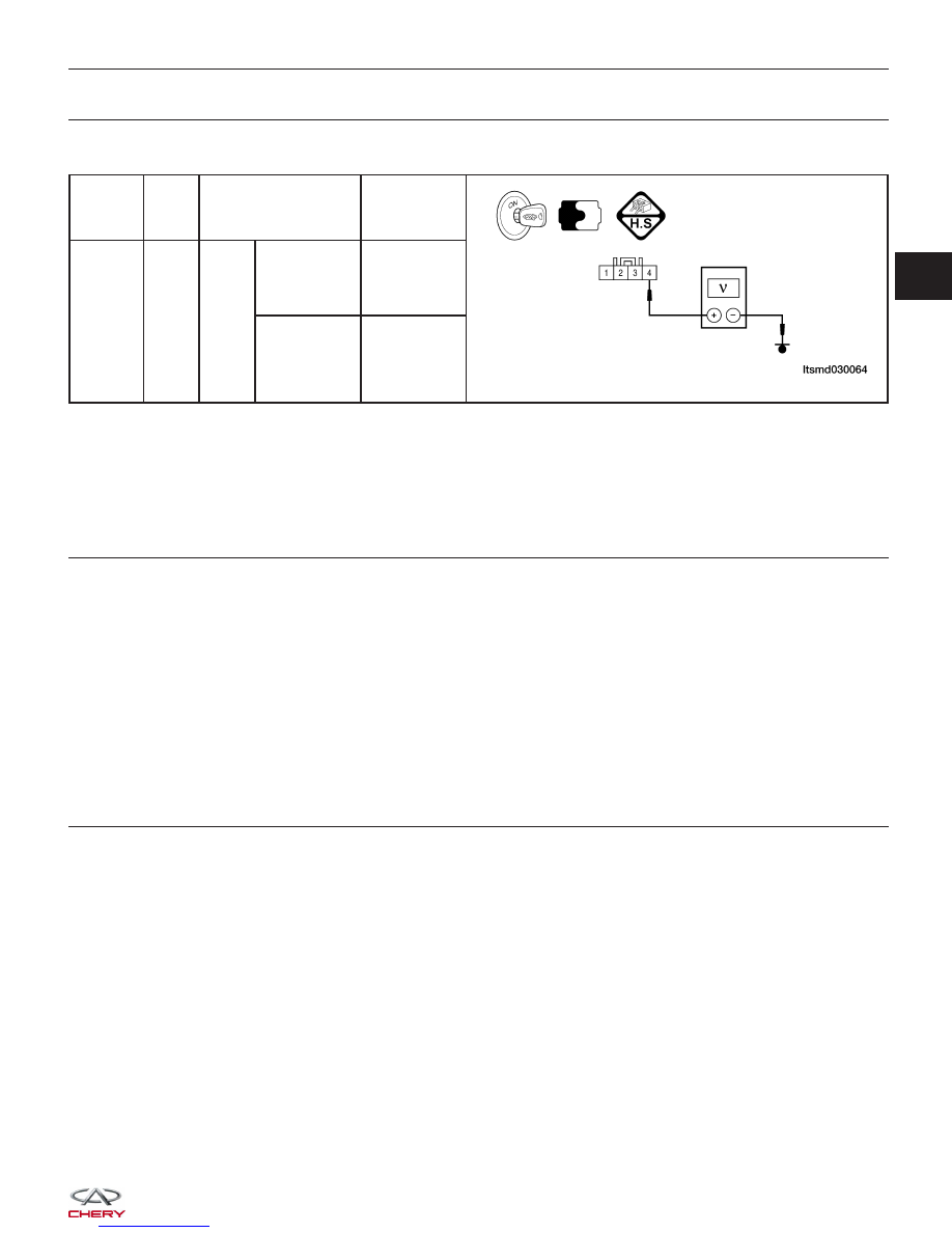
CHECK THE MAP SENSOR SIGNAL

• Check MAP sensor signal between sensor terminal 4 and ground.

TERMINAL

NO.

ITEM

CONDITION

DATA (DC

VOLTAGE)

4

MAP

sensor

Engine:

Running

• Press

accelerator

pedal slowly.

Approximately
1.3 V

• Press

accelerator

pedal quickly.

Up to
approximately
4 V
(instantaneous)

Is the check result normal?

Yes

>>

Go to step 9.

No

>>

Go to the next step.

8.

CHECK AND REPLACE THE MAP SENSOR

• Check sensor as follow.

− Remove the sensor.
− Visually check and clean the pressure entrance of the sensor for chipping.

Is the check result normal?

Yes

>>

Replace the MAP sensor with a known good MAP sensor.
Select view DTC on the X-431 screen.
− If DTC P0107 or P0108 is not current present, the system is OK.
− If DTC P0107 or P0108 is current present, go to step 9.

No

>>

Clear or replace the MAP sensor.

9.

CHECK DTC

• With the X-431 scan tool, read ECM DTCs.

• Refer to ⬙DTC Confirmation Procedure⬙.

Is DTC P0107 or P0108 still present?

Yes

>>

Replace the ECM.

NOTE : The Immobilizer control module must be matched to the new ECM (See ECM Removal & Instal-

lation in Section 03 Electronic Engine Controls).

No

>>

The system is now operating properly.
Reassemble the vehicle and road test to verify the customers complaint is repaired.

DIAGNOSIS & TESTING

03


P0112 - Intake Air Temperature Circuit Low Input

DIAGNOSIS & TESTING

LTSMW030052T


DIAGNOSIS & TESTING

LTSMW030058T

03


Check reference values between ECM terminals and ground under the following conditions:

ECM TERMINAL

NO.

ITEM

CONDITION

DATA (DC

VOLTAGE)

17

Sensor (GND)

Ignition switch: ON

0 V

42

Intake Air

Temperature (IAT)

sensor

Ignition switch: ON

Intake Air

Temperature (IAT):

36°C

1.88 V

On Board Diagnostic Logic
• Self-diagnosis detection logic.

DTC NO.

DTC DEFINITION

DTC DETECTION

CONDITION

DTC SET

CONDITION

POSSIBLE CAUSE

P0112

Intake Air

Temperature (IAT)

circuit low input

• Ignition switch:
ON

• Engine: Running

Output signal is
wrong or out of
acceptable range.

• IAT sensor

• Harness or
connectors

• ECM

DTC Confirmation Procedure:

Before performing the following procedure, confirm that battery voltage is more than 12 V.

• Turn ignition switch off.

• Connect the X-431 scan tool to the Data Link Connector (DLC) - use the most current software available.

• Turn ignition switch on.

• With the scan tool, record and erase stored DTCs in the ECM.

• Start engine and warm it to normal operating temperature, then select view DTC and data stream.

• If the DTC is detected, the DTC condition is current. Go to Diagnostic Procedure - Step 1.

• If the DTC is not detected, the DTC condition is intermittent (See Diagnostic Help and Intermittent DTC Trou-

bleshooting in Section 03 Electronic Engine Controls for more information.

NOTE :
While performing electrical diagnosis & testing, always refer to the electrical schematics for specific circuit
and component information.

Diagnostic Procedure

1.

CHECK GROUND CONNECTIONS

• Turn ignition switch off.

• Loosen and retighten ground screws on the body (See Ground Inspection in Section 03 Electronic Engine Con-

trols).

• Inspect ground connections E-207 and E-208 mounting position (See Vehicle Wiring Harness Layout - Engine

Room Harness (With 1.6L/1.8L Engine) in Section 16 Wiring).

Are the ground connections OK?

Yes

>>

For 1.8L engine go to next step.
For 1.6L engine go to Step 4.

No

>>

Repair or replace ground connections.

DIAGNOSIS & TESTING


Content   ..  89  90  91  92   ..