Chery Tiggo. Manual - part 88


  Index      Chery     Chery Tiggo - service repair manual 2009 year


Search            


Content   ..  86  87  88  89   ..


Chery Tiggo. Manual - part 88


Diagnostic Procedure

1.

CHECK GROUND CONNECTIONS

• Turn ignition switch off.

• Loosen and retighten ground screws on the body (See Ground Inspection in Section 03 Electronic Engine Con-

trols).

• Inspect ground connections E-207 and E-208 mounting position (See Vehicle Wiring Harness Layout - Engine

Room Harness (With 1.6L/1.8L Engine) in Section 16 Wiring).

Is ground connections OK?

Yes

>>

Go to the next step.

No

>>

Repair or replace ground harness or connections.

2.

CHECK INTAKE SYSTEM

• Check the following for connection.

− Air cleaner
− Intake air duct

Is the check result normal?

Yes

>>

Go to the next step.

No

>>

Clean or replace the components.
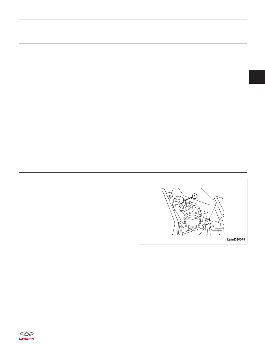
3.

CHECK MASS AIR FLOW (MAF) SENSOR ELECTRICAL CONNECTOR

• Disconnect the MAF sensor (1) electrical connector.

• Inspect the electrical connector for damage.

Is the electrical connector OK?

Yes

>>

Go to the next step.

No

>>

Repair or replace the electrical connector

as necessary.

DIAGNOSIS & TESTING

LTSMD030075

03


4.

CHECK THE MASS AIR FLOW (MAF) SENSOR POWER SUPPLY CIRCUIT

• Turn ignition switch on.

• Check voltage between the MAF sensor terminal 4

and ground in the MAF sensor electrical connector
E-009.

• 5 V should exist.

Is the check result normal?

Yes

>>

Go to step 6.

No

>>

Go to the next step.

5.

DETECT MALFUNCTIONING PART

• Check harness for short to power between air flow sensor and ECM.

Is the check result normal?

Yes

>>

Go to the next step.

No

>>

Repair or replace the circuit for short to power in harness or connectors.

6.

CHECK THE MAF SENSOR GROUND CIRCUIT FOR A SHORT

• Turn ignition switch off.

• Disconnect ECM harness connector.

• Check harness continuity between MAF sensor terminal 3 and ECM terminal 17.

• Continuity should exist.

• Also check harness for short to power.

Is the check result normal?

Yes

>>

Go to the next step.

No

>>

Repair or replace the circuit for a short to power in harness or connectors.

7.

CHECK THE MAF SENSOR OUTPUT SIGNAL CIRCUIT FOR SHORT TO POWER

• Check harness continuity between MAF sensor terminal 5 and ECM terminal 37.

• Continuity should exist.

• Also check harness for short to power.

Is the check result normal?

Yes

>>

Go to the next step.

No

>>

Repair or replace circuit for short to power in harness or connectors.

DIAGNOSIS & TESTING

LTSMD030042


8.

CHECK THE MAF SENSOR

• Install all removed parts.

• Start engine.

• Check air flow signal in data stream with the X-431.

TERMINAL

NO.

ITEM

CONDITION

DATA

(AVERAGE

DC

VOLTAGE)

37

Air

flow

sensor

• Engine is

running

• ECT: 78°C

• Idle: 795

RPM

• IAT: 36°C

• IAT signal:

1.88 V

Approximately

322 kg/h

Approximately

1.39 V

• If without the X-431, check voltage between MAF sensor terminal 5 and ground.

TERMINAL

NO.

ITEM

CONDITION

DATA

(AVERAGE

DC

VOLTAGE)

37

Air

flow

sensor

• Engine is

running

• ECT: 78°C

• Idle: 795

RPM

• IAT: 36°C

• IAT signal:

1.88 V

Approximately

1.39 V

Is the signal voltage of MAF normal?

Yes

>>

Go to the next step.

No

>>

Replace the MAF sensor.

9.

CHECK DTC

• With the X-431 scan tool, read ECM DTCs.

• Refer to ⬙DTC Confirmation Procedure⬙.

Is DTC P0103 still present?

Yes

>>

Replace the ECM.

NOTE : The Immobilizer control module must be matched to the new ECM (See ECM Removal & Instal-

lation in Section 03 Electronic Engine Controls).

No

>>

The system is now operating properly.
Reassemble the vehicle and road test to verify the customers complaint is repaired.

DIAGNOSIS & TESTING

03


P0105 - Manifold Absolute Pressure/Barometric Pressure Circuit
P0106 - Manifold Absolute Pressure Or Barometric Pressure Range/Performance

DIAGNOSIS & TESTING

LTSMW030052T


Content   ..  86  87  88  89   ..