Chery Tiggo. Manual - part 86


  Index      Chery     Chery Tiggo - service repair manual 2009 year


Search            


Content   ..  84  85  86  87   ..


Chery Tiggo. Manual - part 86


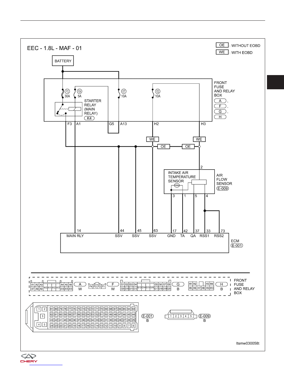
P0102 - Mass Or Volume Air Flow Circuit Low Input

DIAGNOSIS & TESTING

LTSMW030058T

03


Check reference values between ECM terminals and ground under the following conditions:

ECM TERMINAL NO.

ITEM

CONDITION

DATA (AVERAGE DC

VOLTAGE)

17

Sensor (GND)

• Engine is running

• Warm-up condition:
78°C

• Idle: 795 RPM

• IAT: 36°C

• IAT signal voltage: 1.88
V

Approximately 0 V

33

Regulated sensor supply 1

5 V

37

Air flow sensor

Approximately 322 kg/h

Approximately 1.39 V

73

Regulated sensor supply 1

5 V

On Board Diagnostic Logic
• Self-diagnosis detection logic.

DTC NO.

DTC DEFINITION

DTC DETECTION

CONDITION

DTC SET

CONDITION

POSSIBLE CAUSE

P0102

Mass or Volume Air
Flow (MAF) circuit
low input

Ignition switch on or
engine is running

ECM detected that
the input signal is
out of the
acceptable range.

• MAF sensor

• Intake air leaks

• Harness or
connectors (The
sensor circuit is open
or shorted)

• ECM

DTC Confirmation Procedure:

Before performing the following procedure, confirm that battery voltage is more than 12 V.

• Turn ignition switch off.

• Connect the X-431 scan tool to the Data Link Connector (DLC) - use the most current software available.

• Turn ignition switch on.

• With the scan tool, record and erase stored DTCs in the ECM.

• Start engine and warm it to normal operating temperature, then select view DTC and data stream.

• If the DTC is detected, the DTC condition is current. Go to Diagnostic Procedure - Step 1.

• If the DTC is not detected, the DTC condition is intermittent (See Diagnostic Help and Intermittent DTC Trou-

bleshooting in Section 03 Electronic Engine Controls for more information.

NOTE :
While performing electrical diagnosis & testing, always refer to the electrical schematics for specific circuit
and component information.

Diagnostic Procedure

1.

CHECK GROUND CONNECTIONS

• Turn ignition switch off.

• Loosen and retighten ground screws on the body (See Ground Inspection in Section 03 Electronic Engine Con-

trols).

• Inspect ground connections E-207 and E-208 mounting position (See Vehicle Wiring Harness Layout - Engine

Room Harness (With 1.6L/1.8L Engine) in Section 16 Wiring).

Is ground connections OK?

Yes

>>

Go to the next step.

No

>>

Repair or replace ground connections.

DIAGNOSIS & TESTING


2.

CHECK INTAKE SYSTEM

• Check the following:

− Air duct
− Vacuum hoses
− Intake air passage between air duct and manifold

Is the check result normal?

Yes

>>

Go to the next step.

No

>>

Reconnect the connectors or replace the malfunctioning part.

3.

CHECK MASS AIR FLOW (MAF) SENSOR ELECTRICAL CONNECTOR

• Disconnect the MAF sensor (1) electrical connector.

• Inspect the electrical connector for damage.

Is the electrical connector OK?

Yes

>>

Go to the next step.

No

>>

Repair or replace the electrical connector

as necessary.

4.

CHECK THE MASS AIR FLOW (MAF) SENSOR POWER SUPPLY CIRCUIT

• Turn ignition switch on.

• Check voltage between MAF sensor terminal 2 and

ground in the MAF sensor electrical connector
E-009.

• Battery voltage should exist.

Is the check result normal?

Yes

>>

Go to step 6.

No

>>

Go to the next step.

DIAGNOSIS & TESTING

LTSMD030075

LTSMD030041

03


5.

DETECT MALFUNCTIONING PART

• Check the following:

With EOBD

− Fuse 21, fuse 22, fuse 24, fuse 27
− Front fuse and relay box H2, H3, F3, A1, A13, G5
− Harness between air flow sensor and fuse

Without EOBD

− Fuse 21, fuse 24, fuse 27
− Front fuse and relay box F3, A1, A13, G5
− Harness between air flow sensor and fuse

Is the check result normal?

Yes

>>

Go to the next step.

No

>>

Repair or replace malfunctioning parts as necessary.

6.

CHECK THE MAF SENSOR REFERENCE CIRCUIT

• Check voltage between MAF sensor terminal 4 and

ground in the MAF sensor electrical connector
E-009.

• 5 V should exist.

Is the check result normal?

Yes

>>

Go to the next step.

No

>>

Repair or replace the circuit for an open
or short to ground in harness or connec-
tors.
If circuit is normal, go to the next step.

7.

CHECK THE MAF SENSOR GROUND CIRCUIT FOR AN OPEN OR SHORT

• Turn ignition switch off.

• Disconnect ECM harness connector.

• Check harness continuity between MAF sensor terminal 3 and ECM terminal 17.

• Continuity should exist.

• Check harness for short to ground.

Is the check result normal?

Yes

>>

Go to the next step.

No

>>

Repair or replace circuit for an open in harness or connectors.

DIAGNOSIS & TESTING

LTSMD030042


Content   ..  84  85  86  87   ..