Chery Tiggo. Manual - part 64


  Index      Chery     Chery Tiggo - service repair manual 2009 year


Search            


Content   ..  62  63  64  65   ..


Chery Tiggo. Manual - part 64


Inspection

Cylinder Bore

• Check the inner diameter of each cylinder bore (See Cylinder Bore Inspection in Section 02 Engine).

CYLINDER BORE

All Cylinders

86.50 - 86.53 mm

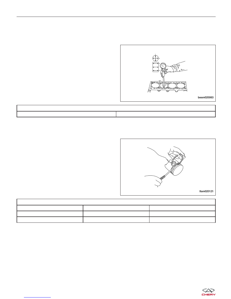
Ring Groove Side Clearance

• Check piston ring to groove side clearance.

− Clean the ring slot using a suitable tool.
− Measure piston ring to groove side clearance.

RING GROOVE SIDE CLEARANCE

DESCRIPTION

SPECIFICATION

LIMIT

First Ring

0.02 - 0.06 mm

0.1 mm

Second Ring

0.02 - 0.06 mm

0.1 mm

ENGINE UNIT REPAIR

BESM020063

LTSM020121


Ring End Gap

• Wipe the cylinder bore clean. Insert ring and push down with piston to ensure it is square in the bore. The ring

gap measurement must be made with the ring posi-
tioned at least 13 mm from bottom of cylinder bore
and below the bottom of the oil ring travel where
the cylinder bore has minimal wear. Check gap with
feeler gauge.

RING END GAP

DESCRIPTION

SPECIFICATION

LIMIT

First Ring

0.25 - 0.35 mm

0.8 mm

Second Ring

0.40 - 0.55 mm

0.8 mm

Oil Control Ring

0.10 - 0.40 mm

1.0 mm

Piston Pin Clearance

• Check the diameter of the piston pin bore.

• Check the outer diameter of the piston pin.

ENGINE UNIT REPAIR

BESM020052

BESM020053

02


• Check the inner diameter of connecting rod (small end).

PISTON PIN CLEARANCE

Piston and Piston Pin

0.002 - 0.013 mm

Assembly

Piston Pin Installation

• Measure the following dimensions of each piston

(1), piston pin (2) and connecting rod (3).

− Length of piston pin in hole (A).
− Width of pin sockets (B).
− Length of piston pin (C).
− Width of small end of connecting rod (D).

• Put measured sizes above into following formula to

calculate L.

− L=[(A-C)-(B-D)] / 2

• After inserting the push rod of the special tool into piston pin, install pipe A in the top of the push rod.

• Install forward marks of piston and connecting rod in the same direction.

• Lubricate the external diameter of piston pin with engine oil.

• Through pipe A, insert the push rod, piston pin and pipe component into piston pin hole from the side with the

forward mark.

• Screw on guide block B into guide pipe A to gain clearance between guide block A (2) and guide block B (1)

equal to the value of Value L (L=[(A-C)-(B-D)] / 2)
plus 3 mm.

• Keep the forward mark of piston upward. Install piston and connecting rod in tool base of piston pin installer.

ENGINE UNIT REPAIR

BESM020054

LTSM020111

LTSM020112


• Using a press, press the piston pin (1) in under pressure. When the pressure is less than standard value,

replace piston pin and piston component and/or
replace connecting rod.standard value: 7,350-
17,200 Newtons

• Check to make sure the piston can rotate freely.

Piston Ring Installation

NOTE :
The compression rings have an identification mark (1)
on the top of the ring.

Piston Ring Identification Marks:
• No. 1 Ring - 1R

• No. 2 Ring - 2R
When installing piston ring, keep the mark upwards and
towards the top of piston.

• Size markings of pistons shown as the following:

SIZE

IDENTIFICATION

Standard

None

Increase 0.50 mm

50

Increase 1.00 mm

100

CAUTION:
Do not use a piston ring expander to install the oil control rings.

Oil Control Ring Installation
• Install the main ring of oil control ring into oil ring groove.

NOTE :
There is no difference between the upper and lower oil control rings.

ENGINE UNIT REPAIR

LTSM020113

LTSM020116

02


Content   ..  62  63  64  65   ..