Chery Tiggo. Manual - part 62


  Index      Chery     Chery Tiggo - service repair manual 2009 year


Search            


Content   ..  60  61  62  63   ..


Chery Tiggo. Manual - part 62


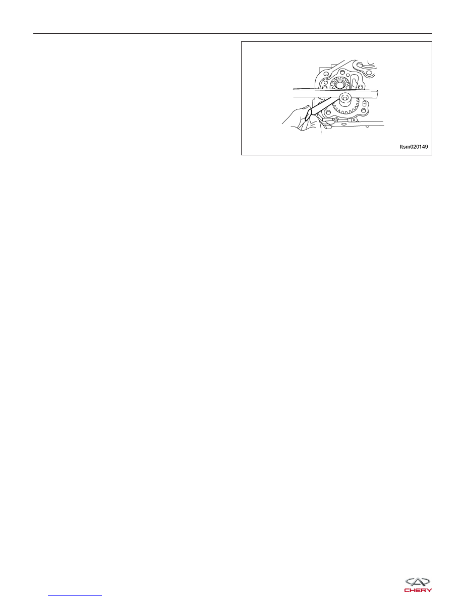
Oil Pump Clearance Specifications

− Driving Gear: 0.08-0.14 mm
− Driven Gear: 0.06-0.12 mm

Oil Strainer

Removal & Installation

1. Raise and support the vehicle.

2. Remove the oil pan (See Oil Pan Removal & Installation in Section 02 Engine).

3. Remove the oil strainer retaining bolts.

(Tighten: Oil strainer bolts to 18 N·m)

4. Carefully remove the oil strainer.

5. Installation is in the reverse order of removal.

Installation Notes:
• Install new O-rings on the oil strainer pipe.

ON-VEHICLE SERVICE

LTSM020149


ENGINE UNIT REPAIR

Engine Block

Specifications

Torque Specifications

DESCRIPTION

TORQUE (N·m)

Connecting Rod Cap Nuts

1st Step: Tighten the nuts to 20 N·m

2nd Step: Tighten the nuts an additional 90°-100°

Main Bearing Cap Bolts

1st Step: Tighten the bolts to 25 N·m

2nd Step: Tighten the bolts an additional 90°-100°

Clearance Specifications

DESCRIPTION

SPECIFICATION (mm)

Surface Distortion Limit

0.15

Cylinder Diameter Standard

86.50 - 86.53

Out-Of-Round

< 0.008

Taper

< 0.01

02


Disassembly

1. Remove the oil pan.

2. Remove the oil strainer.

3. For each connecting rod/piston assembly to be removed, rotate the crankshaft to the bottom dead center position

for each cylinder.

NOTE :
Before removing the connecting rod/piston assembly, check the connecting rod side clearance.

1 - Cylinder Block

2 - Crankshaft Thrust Bearing

3 - Upper Crankshaft Bearing

4 - Crankshaft

5 - Lower Crankshaft Bearing

6 - Bearing Cap

7 - Bearing Cap Bolt

ENGINE UNIT REPAIR

LTSM020124


4. Remove the connecting rod retaining bolts.

5. Remove the connecting rod bearing cap.

6. Using a hammer handle or similar tool, push the

connecting rod/piston assembly (1) out through the
top of the cylinder block.

7. Remove the connecting rod bearings (See Con-

necting Rod Removal & Installation in Section 02
Engine).
CAUTION: When removing the connecting rod
side bearings, note the installation position.
Keep them in the correct order.

8. Installation is in the reverse order of removal.

ENGINE UNIT REPAIR

BESM020042

BESM020043

BESM020044

BESM020045

02


Content   ..  60  61  62  63   ..