Chery Tiggo. Manual - part 44
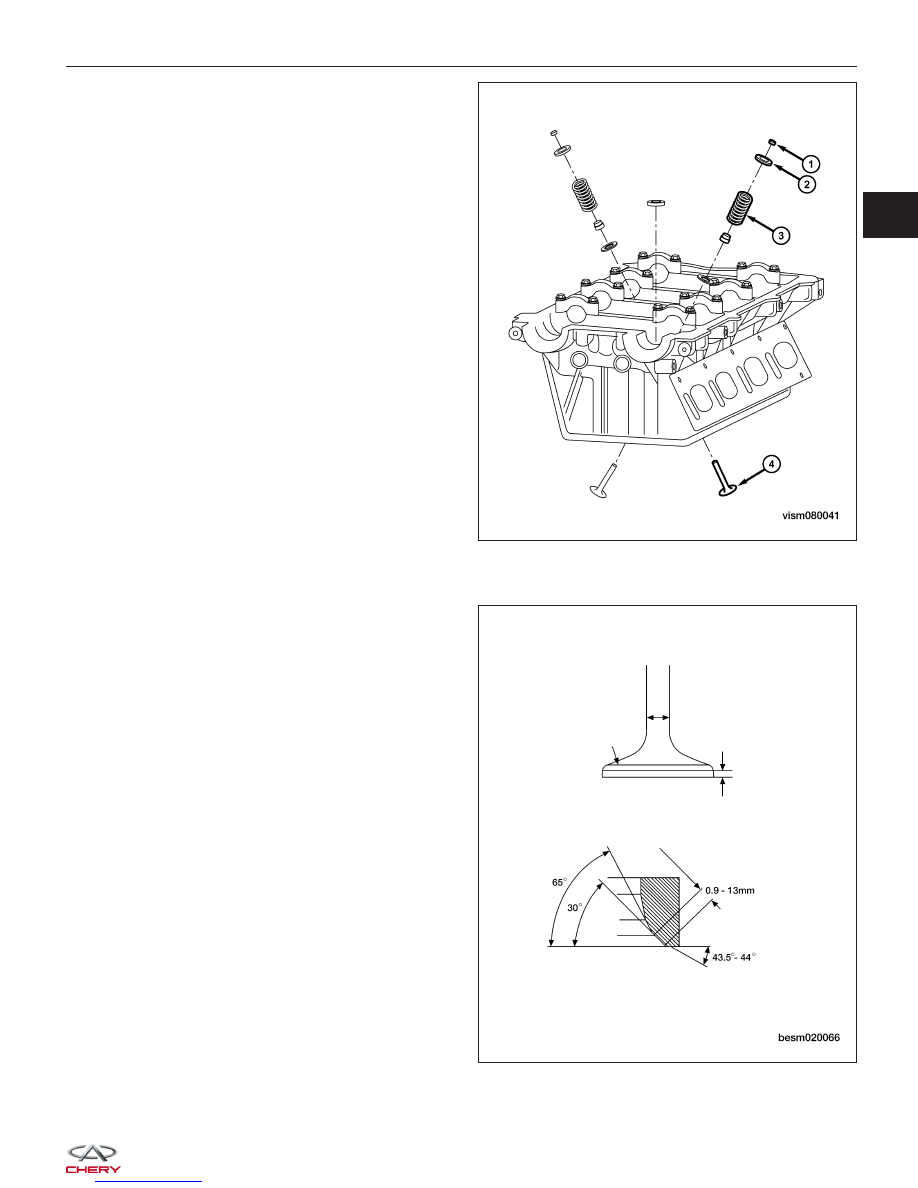
2. Remove the valve keeper (1), valve spring retainer
(2) and valve spring (3).
3. Remove valves (4) from the cylinder head.
Inspection
Inspect the valves for the following:
• Clean all valves thoroughly and discard burned,
warped and cracked valves.
• Check valve seats and valve faces for damage.
• When reconditioning valves follow the specifications
outlined for both intake and exhaust valves.
CYLINDER HEAD UNIT REPAIR
VISM080041
BESM020066
02