Chery Tiggo. Manual - part 45


  Index      Chery     Chery Tiggo - service repair manual 2009 year


Search            


Content   ..  43  44  45  46   ..


Chery Tiggo. Manual - part 45


Assembly

1. Install the valve springs.

2. Install the valve spring retainers.

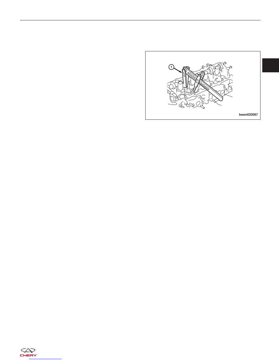
3. Using a valve spring compressor CH-20018 (1),

compress the valve springs.

4. Install the valve keepers.

5. Strike the valve stem lightly with a plastic hammer after installation to verify proper assembly.

CYLINDER HEAD UNIT REPAIR

BESM020067

02


2.4L ENGINE MECHANICAL

GENERAL INFORMATION

02-151

Description

02-151

Operation

02-151

Specifications

02-151

Special Tools

02-154

Lubrication System

02-160

DIAGNOSIS & TESTING

02-163

Engine Performance Diagnostics

02-163

Engine Mechanical Diagnostics

02-164

Cylinder Compression Pressure Test

02-165

Cylinder Head Gasket Test

02-166

Engine Oil Pressure Test

02-166

ON-VEHICLE SERVICE

02-167

Accessory Drive Belt

02-167

Removal & Installation

02-167

Air Cleaner Element

02-168

Removal & Installation

02-168

Air Cleaner Housing

02-169

Removal & Installation

02-169

Cylinder Head Cover

02-170

Removal & Installation

02-170

Camshaft

02-171

Removal & Installation

02-171

Cylinder Head

02-175

Removal & Installation

02-175

Front Crankshaft Oil Seal

02-177

Removal & Installation

02-177

Rear Crankshaft Oil Seal

02-179

Removal & Installation

02-179

Engine Mounts

02-181

Removal & Installation - Left Mount

02-181

Removal & Installation - Right Mount

02-182

Removal & Installation - Front Mount

02-182

Removal & Installation - Rear Mount

02-183

Engine Assembly

02-183

Removal & Installation

02-183

Engine Timing Belt

02-189

Removal & Installation

02-189

Inspection

02-194

Timing Belt Automatic Tensioner

02-196

Removal & Installation

02-196

Inspection

02-197

Upper Balance Shaft Timing Belt

02-198

Removal & Installation

02-198

Exhaust Manifold

02-200

Removal & Installation

02-200

Intake Manifold

02-201

Removal & Installation

02-201

Upper Balance Shaft

02-204

Removal & Installation

02-204

Upper Balance Shaft Bearing
Replacement

02-207

Lower Balance Shaft

02-208

Removal & Installation

02-208

Lower Balance Shaft Bearing
Replacement

02-211

Oil Filter

02-212

Removal & Installation

02-212

Oil Pan

02-213

Removal & Installation

02-213

Oil Pump

02-215

Removal & Installation

02-215

Oil Strainer

02-216

Removal & Installation

02-216

ENGINE UNIT REPAIR

02-217

Engine Block

02-217

Specifications

02-217

Disassembly

02-218

Inspection

02-220

Assembly

02-220

Pistons

02-221

Specifications

02-221

Disassembly

02-222

Inspection

02-224

Assembly

02-226

Connecting Rods

02-229

Specifications

02-229

Disassembly

02-229

Inspection

02-230

Assembly

02-231

Crankshaft

02-233

Specifications

02-233

Disassembly

02-234

Inspection

02-236

Assembly

02-237


CYLINDER HEAD UNIT REPAIR

02-241

Cylinder Head

02-241

Specifications

02-241

Disassembly

02-241

Inspection

02-242

Assembly

02-242

Camshaft

02-243

Specifications

02-243

Disassembly

02-244

Camshaft

02-245

Hydraulic Adjusters

02-245

Rocker Arms

02-246

Valve & Valve Guides

02-246

Specifications

02-246

Disassembly

02-247

Valves

02-248

Valve Guides

02-250

Valve Seats

02-251

Assembly

02-252

Valve Springs

02-252

Specifications

02-252

Disassembly

02-253

Inspection

02-254

Assembly

02-255

ENGINE - 2.4L ENGINE MECHANICAL

02


GENERAL INFORMATION

Description

The 2.4L in-line four cylinder engine has the following features:

• Single overhead camshaft

• Four valves per chamber cylinder head design

• Aluminum cylinder head

• Cast iron cylinder block

Operation

The 2.4L engine utilizes 4 valves-per-cylinder and a single-overhead-camshaft design. The engine uses an individual
coil ignition system and multi-point sequential injection. The cylinder block is made of cast iron and the bearing caps
are integrated into the lower cylinder block assembly. A cast iron oil pan is located at the bottom of the lower cylinder
block. The camshaft is mounted in the cylinder head and acts against the valve tappets to open and close the valves.
The camshaft is driven off the front of the cylinder head by the timing belt. The belt is driven by a sprocket that is
located on the crankshaft. The piston assembly is an aluminum piston with a cast iron connecting rod.

The aluminum cylinder head contains a single overhead camshaft with 4 valves-per-cylinder construction. The valves
are arranged in two in-line banks. The cylinder head incorporates powdered metal valve guides and seats. The cyl-
inder head is sealed to the block using a multi-layer steel head gasket and retaining bolts.

Specifications

2.4L General Engine Specifications

DESCRIPTION

SPECIFICATION

Type

In-Line, OHV, SOHC

Number of Cylinders

4

Compression Ratio

9:1

Output Power (kw)

95 / 5500 RPM

Stroke

100 mm

Cylinder Diameter

86.5 mm

Displacement

2351 cc

Firing Order

1-3-4-2

Max Torque (N·m)

198.1

2.4L Mechanical Specifications

ITEM

STANDARD

LIMIT

Engine Timing

Belt

Tensioner Arm Protrusion

12

-

Tensioner Arm Depression (98-196 N)

≤1

-

Camshaft

Cam Height

Air-In

37.50

37.00

Air-Out

36.99

36.49

Shaft Diameter

45.0

-

Cylinder Head

Lower Surface Flatness

0.03

0.2

Surface Grinding Limit* Total Grinding of Cylinder Block

and Cylinder Head

-

0.2

Full Height

119.9 - 120.1

-


Content   ..  43  44  45  46   ..