Acura CSX. Manual - part 347
*03
*04
−
−
−
−
YES
NO
YES
NO
17-62
EPS Components
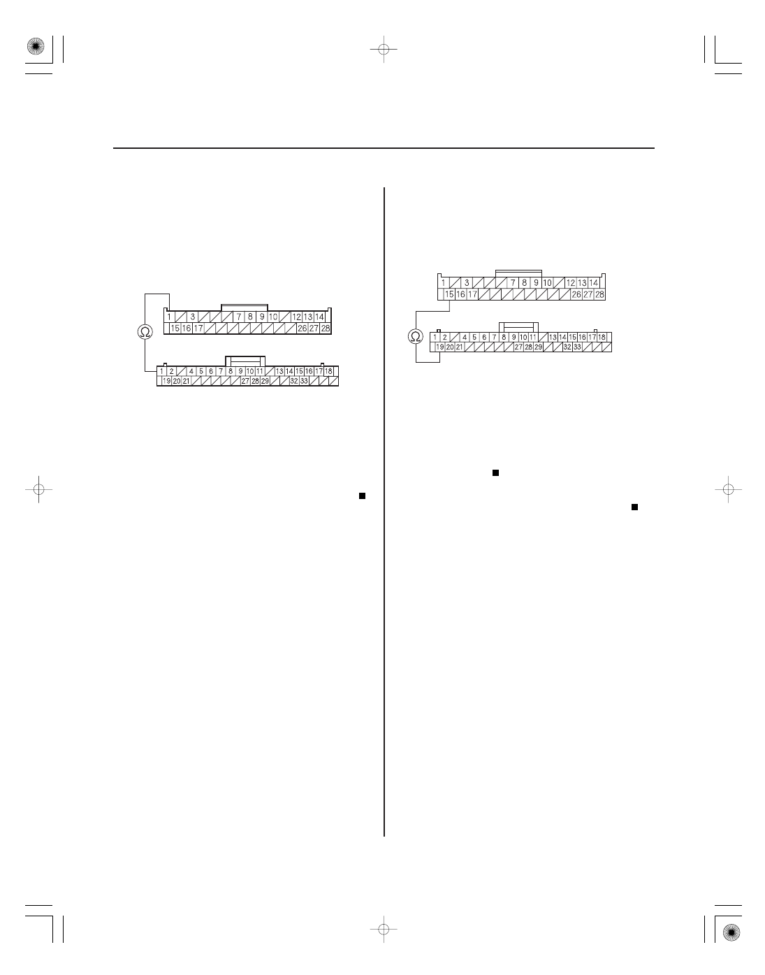
EPS CONTROL UNIT CONNECTOR D (28P)
CAN-H (WHT)
CAN-H (WHT)
GAUGE CONTROL MODULE (TACH) 36P
CONNECTOR
EPS CONTROL UNIT CONNECTOR D (28P)
CAN-L (RED)
CAN-L (RED)
GAUGE CONTROL MODULE (TACH) 36P
CONNECTOR
13. Disconnect the gauge control module (tach) 36P
connector.
14. Check for continuity between EPS control unit
connector D (28P) terminal No. 1 and gauge control
module (tach) 36P connector terminal No. 1.
Go to step 15.
Repair open in the wire between the EPS
control unit and the gauge control module (tach).
15. Check for continuity between EPS control unit
connector D (28P) terminal No. 15 and gauge
control module (tach) 36P connector terminal
No. 19.
Check for loose terminals in the EPS control
unit connectors, and repair if necessary. If no poor
connections are found, replace the EPS control unit
(see page 17-84).
Repair open in the wire between the EPS
control unit and the gauge control module (tach).
Wire side of female terminals
Wire side of female terminals
Wire side of female terminals
Wire side of female terminals
Is ther e continuity?
Is ther e continuity?
08/08/21 14:55:08 61SNR030_170_0063