Acura CSX. Manual - part 348
01
02
03
17-66
EPS Components
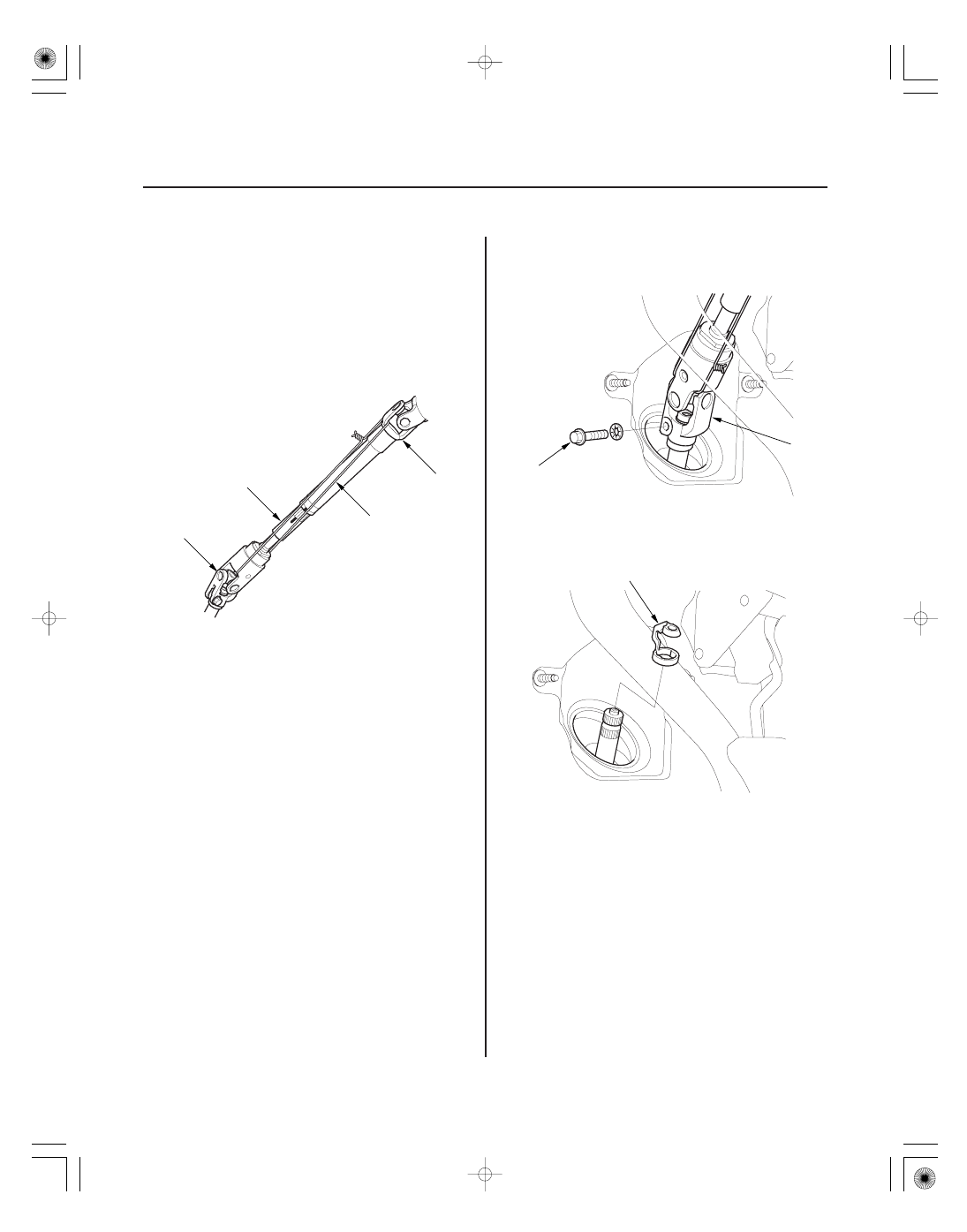
A
B
C
D
A
8 x 1.25 mm
B
A
7. Release the lock lever, and adjust the steering
column to the full tilt up position, and to the full
telescopic in position.
8. Tighten the lock lever.
9. Hold the lower slide shaft (A) on the column with a
piece of wire (B) between the joint yoke (C) of the
lower slide shaft and joint yoke (D) of the upper
shaft to prevent the slider shaft from pulling out.
10. Release the lock lever, and adjust the steering
column to the full telescopic out position, then
tighten the lock lever.
11. Remove the steering joint bolt (A), and disconnect
the steering joint by moving the steering joint (B)
toward the column.
12. Remove the center guide (A) (if equipped), and
discard it. The center guide is for factory assembly
use only.
13. Remove the cowl cover and under cowl panel
(see page 20-163).
14. Remove the air cleaner housing (see page 11-345).
08/08/21 14:55:10 61SNR030_170_0067