Acura CSX. Manual - part 345
02
03
04
05
−
−
−
−
YES
NO
YES
NO
17-54
EPS Components
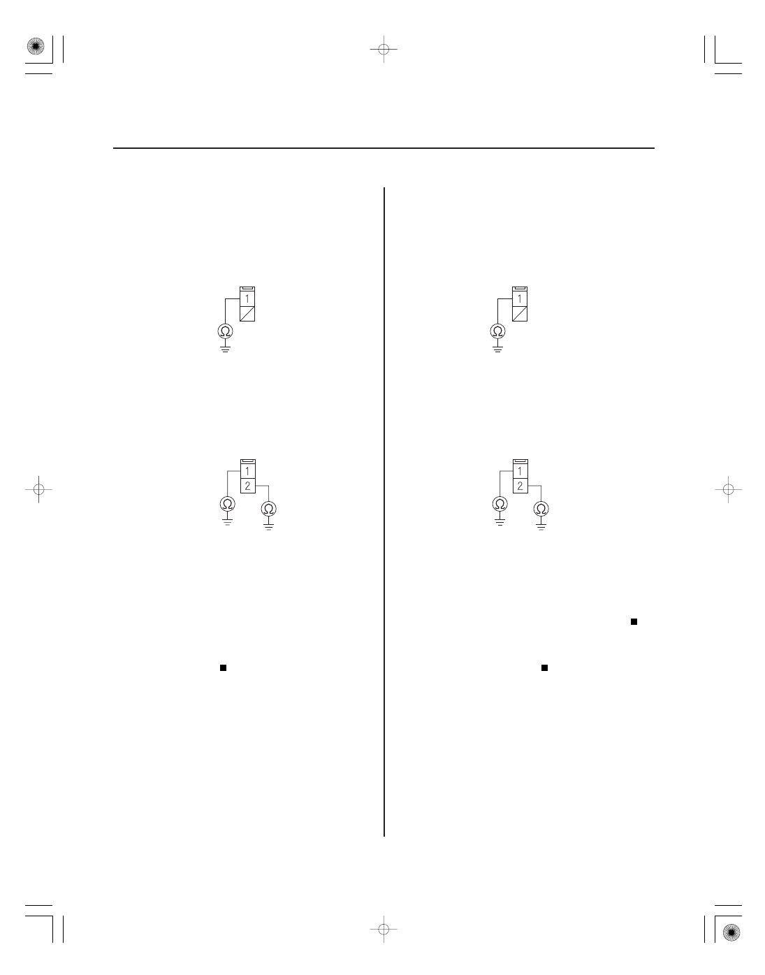
EPS CONTROL UNIT CONNECTOR B (2P)
H-W (GRN)
EPS CONTROL UNIT CONNECTOR C (2P)
H-U (RED)
H-V (BLU)
EPS CONTROL UNIT CONNECTOR B (2P)
H-W (GRN)
EPS CONTROL UNIT CONNECTOR C (2P)
H-U (RED)
H-V (BLU)
10. Check for continuity between body ground and EPS
control unit connector B (2P) terminal No. 1,
connector C (2P) terminal No. 1, and connector C
(2P) terminal No. 2 individually.
Go to step 11.
Check for loose terminals in the EPS control
unit connectors, and repair if necessary. If no poor
connections are found, replace the EPS control unit
(see page 17-84).
11. Disconnect the EPS motor 1P connector and the
EPS motor 2P connector.
12. Check for continuity between body ground and EPS
control unit connector B (2P) terminal No. 1,
connector C (2P) terminal No. 1, and connector C
(2P) terminal No. 2 individually.
Repair short to body ground in the wire
between the EPS control unit and the EPS motor.
Short to the body ground in the EPS motor
wire, or the EPS motor internal circuit, replace the
EPS motor (see page 17-65).
Wire side of female terminals
Wire side of female terminals
Wire side of female terminals
Wire side of female terminals
Is ther e continuity?
Is ther e continuity?
08/08/21 14:54:37 61SNR030_170_0055