Acura CSX. Manual - part 30


  Index      Acura     Acura CSX - P/NO. 61SNR03 - service repair manual 2006-2009 year


Search            


Content   ..  28  29  30  31   ..


Acura CSX. Manual - part 30


*06

*12

07

08

M/T model

A/T model

5-18

Engine Assembly

A

A

C

C

B

B

12 x 1.25 mm
64 N·m
(6.5 kgf·m, 47 lbf·ft)

14 x 1.5 mm
88 N·m
(9.0 kgf·m,
65 lbf·ft)

14 x 1.5 mm
93 N·m
(9.5 kgf·m,
69 lbf·ft)

14 x 1.5 mm
88 N·m
(9.0 kgf·m,
65 lbf·ft)

14 x 1.5 mm
93 N·m
(9.5 kgf·m, 69 lbf·ft)

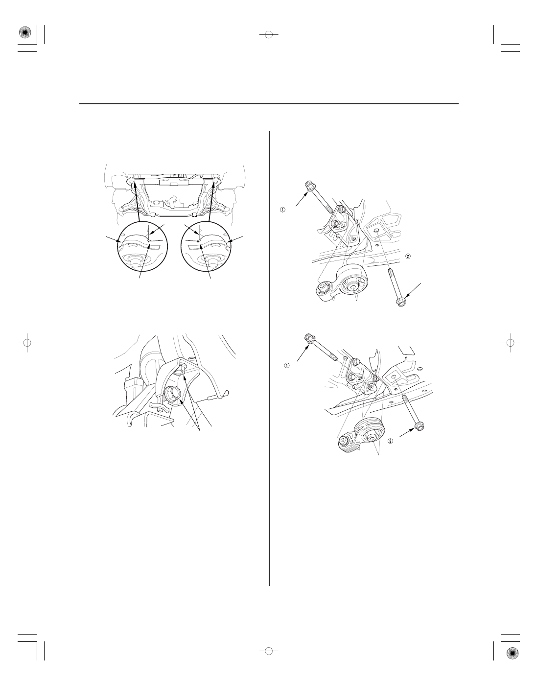
18. Align all reference marks (A) on the front subframe

(B) with the edges of the body (C), then tighten the
bolts on the front subframe to the specified torque.

19. Remove the jack and the front subframe adapter.

20. Tighten the new mid-stiffener mounting bolts on

both side.

21. Install the lower torque rod, then tighten the new

lower torque rod mounting bolts in the numbered
sequence shown.

Replace.

Replace.

Replace.

Replace.

Replace.

06

17

18

19

5-19

A

12 x 1.25 mm
64 N·m
(6.5 kgf·m, 47 lbf·ft)

12 x 1.25 mm
64 N·m
(6.5 kgf·m, 47 lbf·ft)

B

A

8 x 1.25 mm
22 N·m
(2.2 kgf·m, 16 lbf·ft)

22. M/T model: Loosely tighten the new front mount

mounting bolt (A).

23. Lower the vehicle on the lift.

24. Remove the engine support hanger and the engine

hanger adapter from the engine and the vehicle.

25. Tighten the upper torque rod mounting bolt.

26. Raise the vehicle on the lift.

27. M/T model: Tighten the front mount mounting bolt.

28. Install the A/C compressor (A), then connect the

A/C compressor clutch connector (B).

Replace.

20

04

*07

23

5-20

Engine Assembly

D

A

B
10 x 1.25 mm
59 N·m
(6.0 kgf·m, 43 lbf·ft)

C
10 x 1.25 mm
54 N·m
(5.5 kgf·m, 40 lbf·ft)

A

B

C
10 x 1.25 mm
59 N·m
(6.0 kgf·m, 43 lbf·ft)

D
10 x 1.25 mm
54 N·m
(5.5 kgf·m, 40 lbf·ft)

10 x 1.25 mm
38 N·m
(3.9 kgf·m, 28 lbf·ft)

E

F

A

D

B

B

C
10 x 1.25 mm
33 N·m (3.4 kgf·m, 25 lbf·ft)

8 x 1.25 mm
22 N·m (2.2 kgf·m, 16 lbf·ft)

29. Install the stiffener (A), then tighten the steering

gearbox mounting bolt (B) and the stiffener
mounting bolt (C).

30. Install the harness clamp (D) to the subframe.

31. Install the steering gearbox bracket (A).

32. Install the stiffener (B), then tighten the steering

gearbox mounting bolt (C) and the stiffener
mounting bolt (D).

33. A/T model: Install the shift cable (see step 19 on

page 14-245).

34. Install a new set ring on the end of each driveshaft,

then install the driveshafts (see page 16-20). Make
sure each ring ‘‘clicks’’ into place in the differential
and the intermediate shaft.

35. Connect the lower arms to the knuckles (see step 9

on page 18-16).

36. Connect the stabilizer links (see page 18-25).

37. Install the three way catalytic converter (TWC) (A).

Use the new gaskets (B) and the new self-locking
nuts (C).

38. Connect the air fuel ratio (A/F) sensor connector (D).

39. Connect the secondary heated oxygen sensor

(secondary HO2S) connector (E), then install the
grommet (F).

40. Install the splash shield.

Replace.

Replace.

Replace.

24

25

*08

04

5-21

A

A

B

B

6 x 1.0 mm
10 N·m
(1.0 kgf·m, 7.2 lbf·ft)

A

B

41. Lower the vehicle on the lift.

42. Connect the heater hoses.

43. A/T model: Connect the automatic transmission

fluid (ATF) cooler hoses (A) to the transmission,
and secure the hoses with the clips (B) (see page
14-253).

44. Remove the bulkhead, then install the radiator

(see page 10-19).

45. Install the idler pulley base (see step 2 on page

4-34).

46. Install the drive belt (see page 4-31).

47. M/T model: Install the air cleaner bracket.

48. M/T model: Install the shift cables (see step 37 on

page 13-20).

49. M/T model: Install the clutch slave cylinder and the

clutch line bracket mounting bolt (see step 40 on
page 13-21).

50. Connect the fuel feed hose (A) (see page 11-331),

then install the quick-connect fitting cover (B).


Content   ..  28  29  30  31   ..