FANUC AC Servo Amplifiers βi Series. Description Manual (B-65322EN/02) - page 7
B-65322EN/02
SVPM
9.TOTAL CONNECTION DIAGRAM
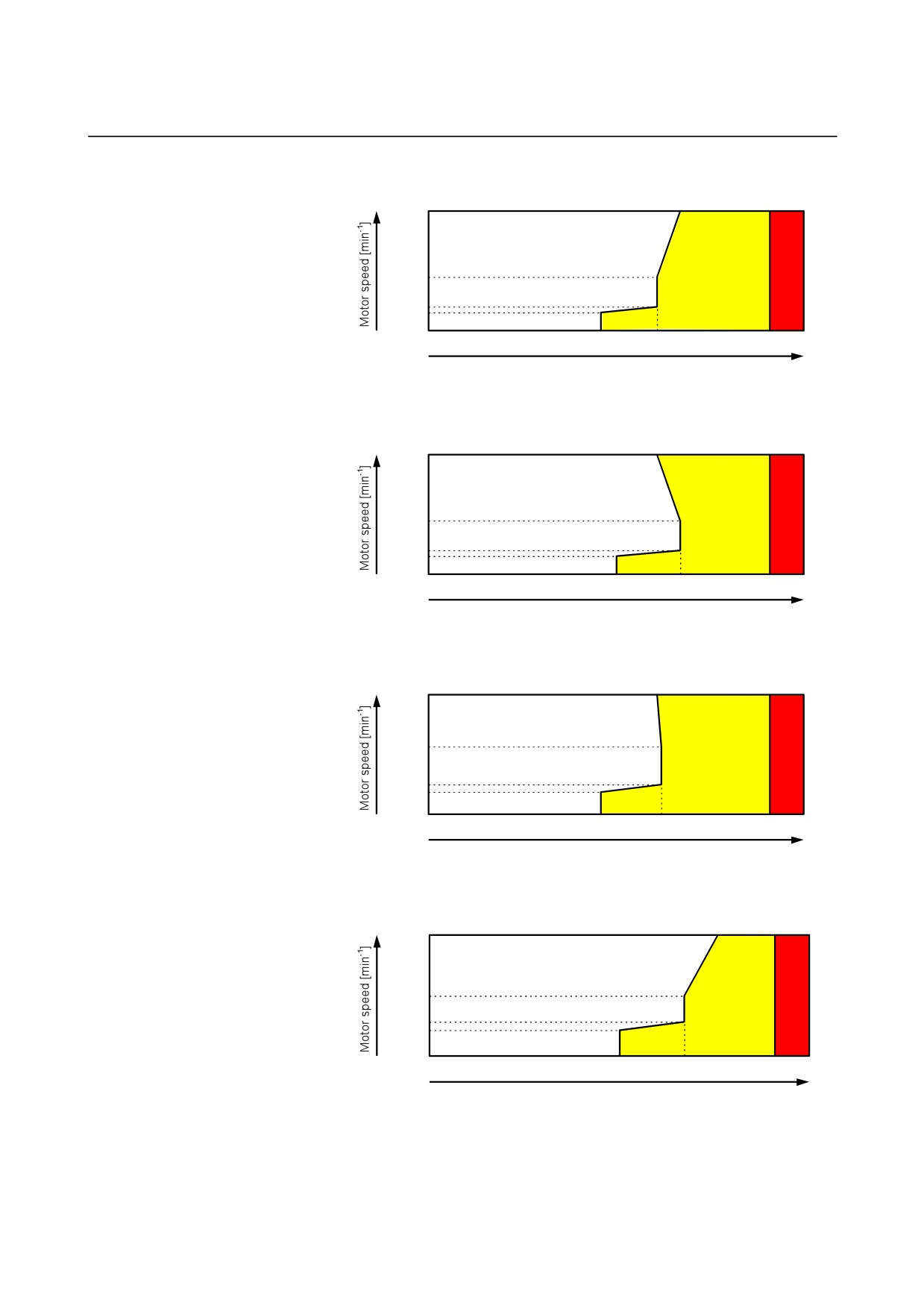
• β3/10000i
6.7
10000
4500
2000
1500
㪇
0
4.6
6.1
9.1
10
Load meter [V]
(Max. 10V)
• β6/10000i
6.1
10000
4500
2000
1500
㪇
0
5.0
6.7
9.1
10
Load meter [V]
(Max. 10V)
• β8/8000i
6.1
8000
4500
2000
1500
0
0
4.6
6.2
9.1
10
Load meter [V]
(Max. 10V)
• β12/7000i
7.6
7000
3500
2000
1500
0
0
5.0
6.7
9.1
10
Load meter [V]
(Max. 10V)
- 167 -
9.TOTAL CONNECTION DIAGRAM
SVPM
B-65322EN/02
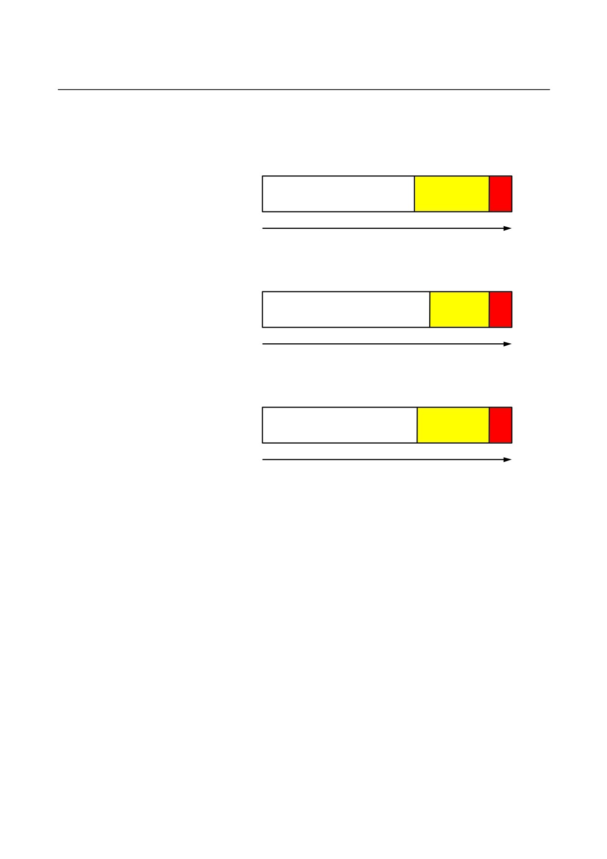
If the motor is often used at a speed of 2000 min-1 or higher, a
simplified version of the load meter shown below could be used.
• β3/10000i
0
6.1
9.1
10
Load meter [V]
• β6/10000i, β12/7000i
0
6.7
9.1
10
Load meter [V]
• β8/8000i
0
6.2
9.1
10
Load meter [V]
- 168 -
B-65322EN/02
SVPM
9.TOTAL CONNECTION DIAGRAM
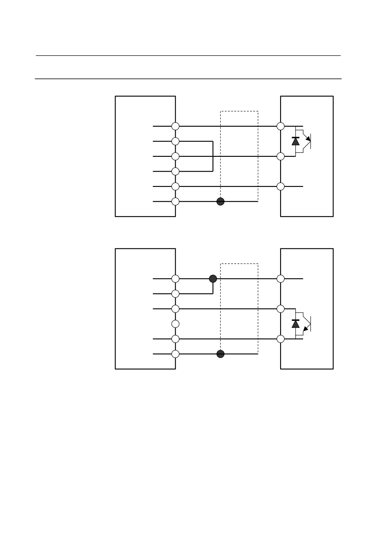
9.3.2.7 Details of cable K71
SVPM JYA3
Proximity switch
Shield
#A
PNP type
(11)
24V
24V
(13)
SCCOM
OUT
(15)
EXTSC
(14)
0V
0V
(16)
0V
(10)
SS
20-pin half-pitch connector
SVPM JYA3
Proximity switch
Shield
#A
NPN type
(11)
24V
24V
(13)
SCCOM
OUT
(15)
EXTSC
(14)
0V
0V
(16)
0V
(10)
SS
20-pin half-pitch connector
- 169 -
9.TOTAL CONNECTION DIAGRAM
SVPM
B-65322EN/02
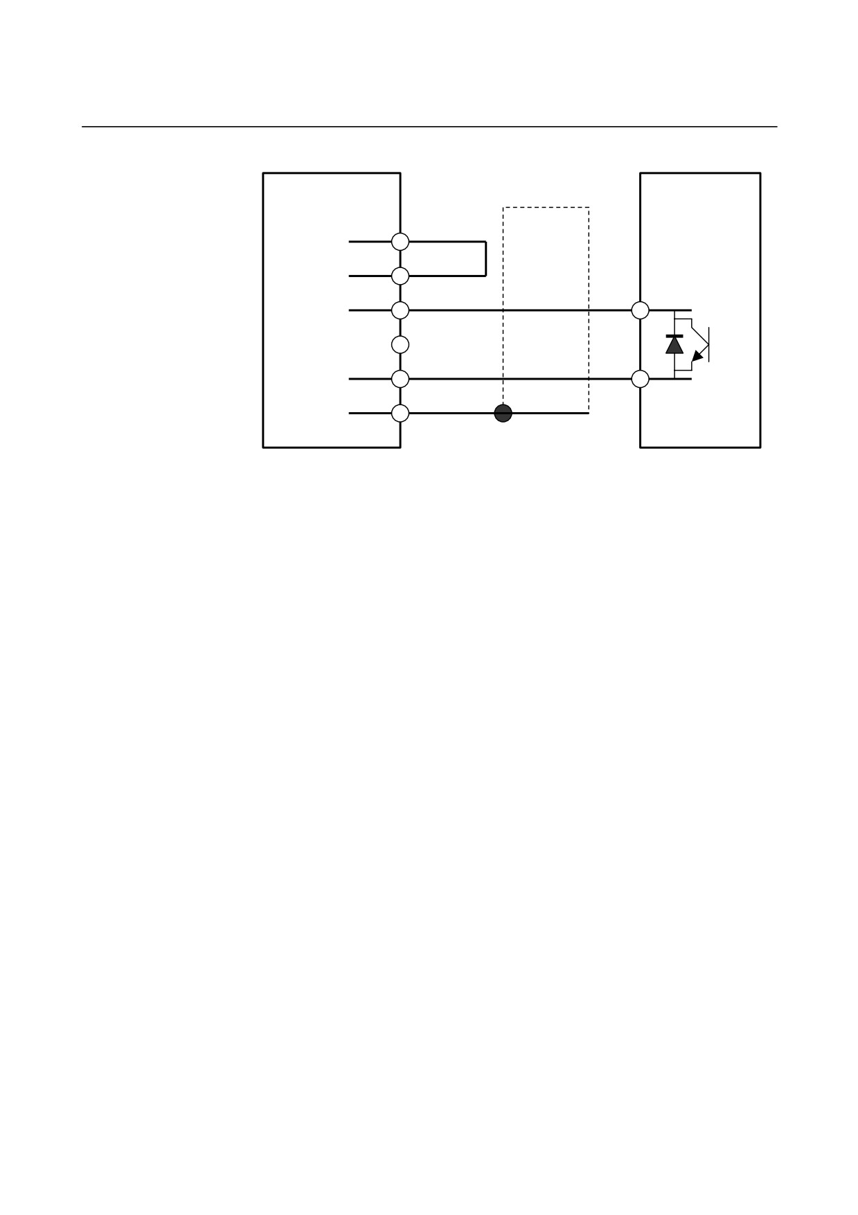
Two-wire
SVPM JYA3
Shield
proximity switch /
#A
(11)
24V
NPN type
(13)
SCCOM
OUT
(15)
EXTSC
(14)
0V
0V
(16)
0V
(10)
SS
20-pin half-pitch connector
Cable specification : 0.09mm2 common shielded cable
Recommended cable conductor : A66L-0001-0284#10P
See Section 5.4.1 for explanations about the JYA3-side connector that
matches the recommended cable.
Connector pin assignment
See Subsection 5.3.3.4 “Details of cable K16.”
- 170 -
B-65322EN/02
SVPM
9.TOTAL CONNECTION DIAGRAM
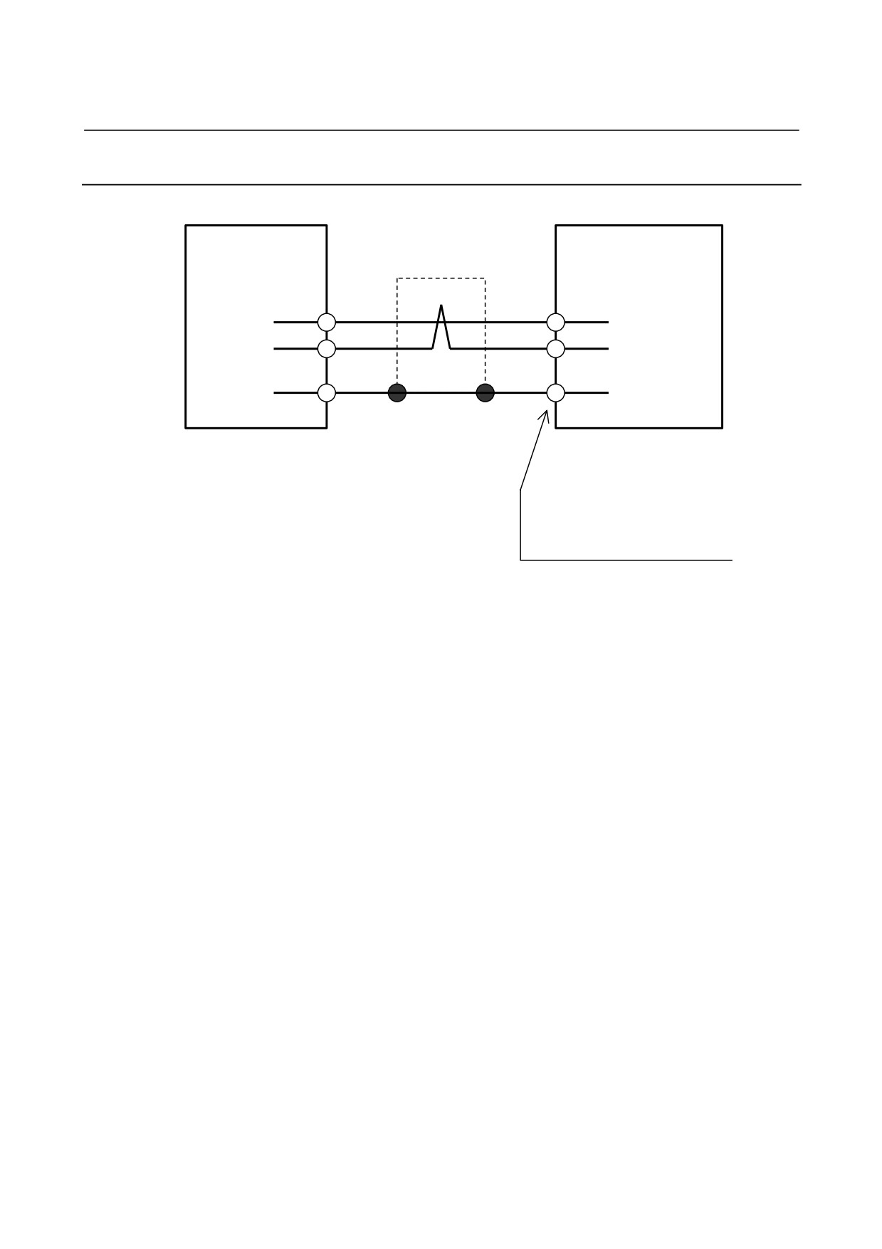
External one-rotation signal switch (proximity switch)
Use an external one-rotation signal switch (proximity switch) that
satisfies the specifications indicated below.
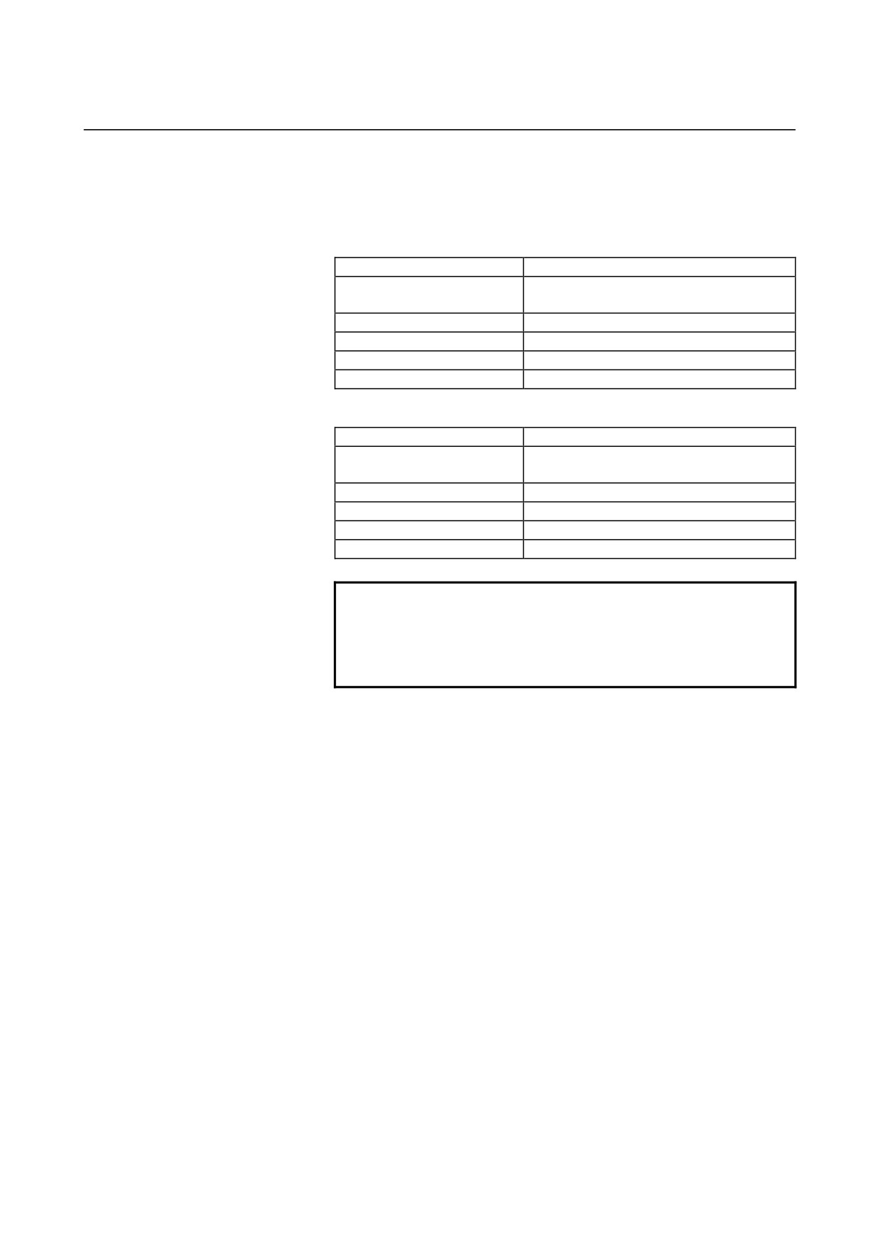
(a) DC two-wire proximity switch
Item
Specification
24 VDC ±1.5 V
Supply voltage
(24 VDC is fed from the SVPM.)
Response frequency
400 Hz or higher
Load current
16 mA or higher
Residual voltage
4 V or higher
Supply (leakage) current
1.5 mA or lower
(b) DC three-wire proximity switch
Item
Specification
24 VDC ±1.5 V
Supply voltage
(24 VDC is fed from the SVPM.)
Response frequency
400 Hz or higher
Load current
16 mA or higher
Residual voltage
4 V or higher
Supply current
50mA or lower
NOTE
The location where a proximity switch signal occurs
depends on the temperature. So, consider the
ambient temperature when selecting a proximity
switch.
- 171 -
9.TOTAL CONNECTION DIAGRAM
SVPM
B-65322EN/02
9.3.2.8 Details of cable K79
SVPM JYA2
Shield
Thermistor
Motor
#C
(13)
THR1
THR1
(A6)
(15)
THR2
THR2
(B6)
(10)
SS
SS
(A5)
20-pin half-pitch connector
Manufactured by tyco Electronics AMP
Housing : 178289-6
Contact : 1-175217-2
Cable specification : 0.18 mm2 twisted pair with common shielded
Recommended cable conductor : A66L-0001-0368
See Section 5.4.1 for explanations about the JYA2-side connector that
matches the recommended cable.
- 172 -

B-65322EN/02
SVPM
9.TOTAL CONNECTION DIAGRAM
9.4
DETAILS OF CONNECTORS
9.4.1
20-Pin Half-Pitch Connectors
The following table lists the 20-pin half-pitch connectors used for the
βi series servo amplifier and the recommended cables for these
connectors.
Use connectors that match the recommended cables specified on the
applicable connection diagram in detail.
Recommended-cable
Applicable
Connector model
Housing model
Connector +
specification
connector
number
number
housing
Hirose Electric Co.,
Sideways cable slot
Sideways cable slot
Ltd.
type
type
FI30-20S
FI-20-CVS2
FI30-20S-CVS2
Crimp type
Honda Tsushin Kogyo
Co., Ltd.
PCR-V20LA
PCR-E20FA
A66L-0001-0284#10P
Hirose Electric Co.,
Sideways cable slot
Sideways cable slot
Ltd.
type
type
FI40B-20S
FI-20-CVS2
FI40B-20S-CVS2
Soldering type
Honda Tsushin Kogyo
Co., Ltd.
PCR-V20LA
PCR-E20FS
A66L-0001-0286
Soldering type
A66L-0001-0460
Note that this
Hirose Electric Co.,
Sideways cable slot
Sideways cable slot
A66L-0001-0462
connector does not
Ltd.
type
type
A66L-0001-0481
have pin No. 11, 13,
FI40B-2015S
FI-2015-CVS
FI40B-2015S-CVS
A66L-0001-0491
15, 17, or 19.
Hirose Electric Co.,
Sideways cable slot
Sideways cable slot
A66L-0001-0368
Soldering type
Ltd.
type
type
FI40B-20S
FI-20-CVS5
FI40B-20S-CVS5
- 173 -
9.TOTAL CONNECTION DIAGRAM
SVPM
B-65322EN/02
9.4.2
Tyco Electronics AMP D-5000 Series Connector
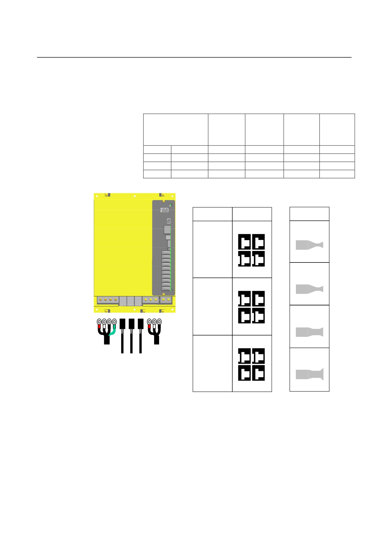
The βi series uses the D-5000 series connector (manufactured by Tyco
Electronics AMP) for the motor power cable.
The connector is provided with three keys that assure it is inserted in
the correct direction. In addition, four types of receptacle contacts are
available, from which the user can select the suitable one depending
on the amount of current to use (size of the conductor).
Connectors and tools can be ordered directly from Tyco Electronics
AMP. FANUC also furnishes options. For details, see “Order List
(B-65321EN)”.
Connector D-5000
Receptacle housing Receptacle contact
Cable
B2
A2
B1
A1
Conductor
Key
Indication of the key type
Receptacle housing
There are three different key types for the receptacle housing. Be sure
to select the receptacle housing of the key type that matches the servo
axis you use.
Receptacle housing
Specification of the
Applicable servo
model number
key
amplifier
1-917807-2
XX
Servo L-axis
3-917807-2
XY
Servo M-axis
2-917807-2
YY
Servo N-axis
(Reference)
There is a cable-end connectors which are inserted no matter
what key is used. Contact the connector manufacturer (Tyco
Electronics AMP) for details.
- 174 -
B-65322EN/02
SVPM
9.TOTAL CONNECTION DIAGRAM
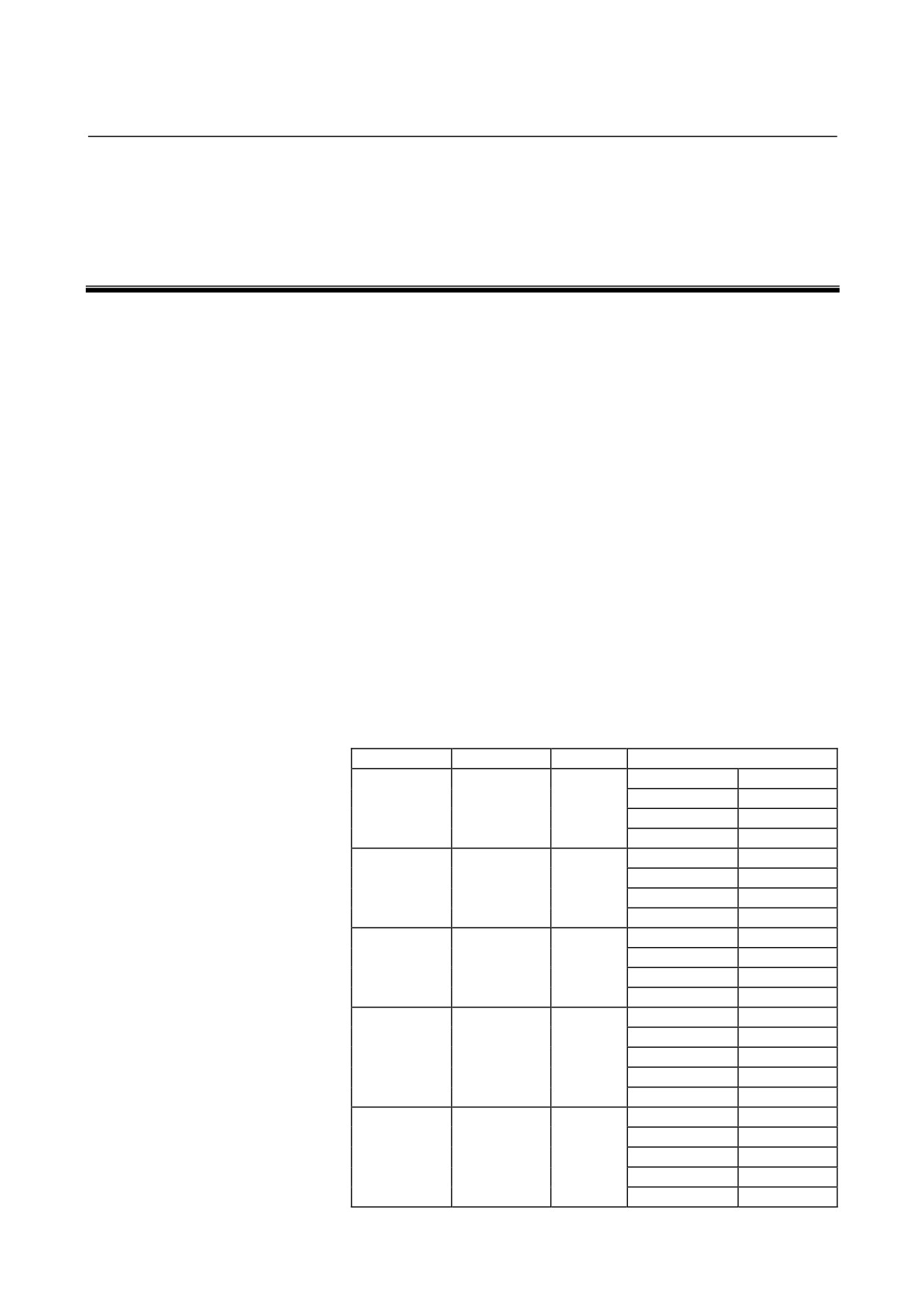
Receptacle contact
Four receptacle contact types are available, so as to support different
conductor diameters. Be sure to select the receptacle contact (silver
plating) that matches the servo axis you use.
Insulation
Manual
Conductor
Conductor
Rectangle contact
outer
tool
size
size
model number
diameter
model
(mm2)
AWG
(mm)
number
SS size
1318986-6
0.50
- 1.42
20/18
1.08-3.23
1366656-1
S size
316040-6
1.23
- 2.27
16/14
3.0-3.8
234170-1
M size
316041-6
3.08
- 5.50
12/10
4.0-5.2
234171-1
L size
1318697-6
7.27
- 8.92
8
4.9-7.8
1366044-1
Applied
Connector key
Contact
Servo
XX
SS
L-axis
1318986-6
S
1-917807-2
Servo
XY
M-axis
316040-6
M
3-917807-2
Servo
YY
316041-6
N-axis
Spindle axis
Servo axis
Power input
L
Screw terminal
Connector
Screw terminal
M5
M5
2-917807-2
1318697-6
- 175 -
10.HEAT DISSIPATION
SVPM
B-65322EN/02
10
HEAT DISSIPATION
The amount of heat generated in an SVPM varies depending on its
model, the current flowing through the motor, and the motor output.
(Refer to the respective motor description manuals for the current and
output of each motor.)
(1) Total amount of heat dissipation
The total amount of heat dissipation by the SVPM is calculated
according to the following expression:
Total amount of heat dissipation
= a + Ka1×b1 + Ka2×b2 + Ka3×b3 + Ka4×b4 + Ka5×b5
a
: Amount of heat dissipation determined by the SVPM
model [W]
Ka1 to Ka5
: Coefficient determined by the SVPM
b1
: Total output of motors connected to the SVPM [kW]
b2
: Current flowing through the spindle motor [Arms]
b3
: Current flowing through the servo motor of L-axis [Arms]
b4
: Current flowing through the servo motor of M-axis [Arms]
b5
: Current flowing through the servo motor of N-axis [Arms]
SVPM (total amount of heat dissipation)
Name
Specification
a [W]
Coefficient
Ka1
14.3
Ka2
5.8
SVPM2-5.5i
H201
22
Ka3
5.0
Ka4
5.0
Ka1
14.3
Ka2
5.4
SVPM2-11i
H202
22
Ka3
5.0
Ka4
5.0
Ka1
13.1
Ka2
5.5
SVPM2-15i
H203
22
Ka3
4.6
Ka4
4.6
Ka1
14.3
Ka2
5.8
SVPM3-5.5i
H301
24
Ka3
5.0
Ka4
5.0
Ka5
4.6
Ka1
14.3
Ka2
5.4
SVPM3-11i
H302
24
Ka3
5.0
Ka4
5.0
Ka5
4.6
- 176 -
B-65322EN/02
SVPM
10.HEAT DISSIPATION
SVPM (total amount of heat dissipation)
Name
Specification
a [W]
Coefficient
Ka1
13.1
Ka2
5.5
SVPM3-15i
H303
24
Ka3
4.6
Ka4
4.6
Ka5
4.6
AC reactor
Total amount of heat
Name
Ordering number
Rated output
dissipation
For SVPM2-5.5i
5.5 kW
16 W
For SVPM3-5.5i
A81L-0001-0155
For SVPM2-11i
11 kW
38 W
For SVPM3-11i
For SVPM2-15i
A81L-0001-0156
15 kW
50 W
For SVPM3-15i
- 177 -
10.HEAT DISSIPATION
SVPM
B-65322EN/02
(2) Residual amount of heat in the cabinet
By placing the heat sink section of the SVPM outside the cabinet,
the residual amount of heat in the cabinet can be calculated
according to the expression below.
Residual amount of heat in the cabinet
= a + Ka1×b1 + Ka2×b2 + Ka3×b3 + Ka4×b4 + Ka5×b5
a
: Amount of heat dissipation determined by the SVPM
model [W]
Ka1 to Ka5 : Coefficient determined by the SVPM
b1
: Total output of motors connected to the SVPM [kW]
b2
: Current flowing through the spindle motor [Arms]
b3
: Current flowing through the servo motor of L-axis [Arms]
b4
: Current flowing through the servo motor of M-axis [Arms]
b5
: Current flowing through the servo motor of N-axis [Arms]
SVPM (residual amount of heat in the cabinet)
Name
Specification
a [W]
Coefficient
Ka1
2.1
Ka2
0.9
SVPM2-5.5i
H201
22
Ka3
0.8
Ka4
0.8
Ka1
2.1
Ka2
0.8
SVPM2-11i
H202
22
Ka3
0.8
Ka4
0.8
Ka1
1.3
Ka2
0.6
SVPM2-15i
H203
22
Ka3
0.5
Ka4
0.5
Ka1
2.1
Ka2
0.9
SVPM3-5.5i
H301
24
Ka3
0.8
Ka4
0.8
Ka5
0.7
Ka1
2.1
Ka2
0.8
SVPM3-11i
H302
24
Ka3
0.8
Ka4
0.8
Ka5
0.7
Ka1
1.3
Ka2
0.6
SVPM3-15i
H303
24
Ka3
0.5
Ka4
0.5
Ka5
0.5
- 178 -
B-65322EN/02
SVPM 11.POWER CABLE FOR SERVO MOTOR AND AMPLIFIER
11
POWER CABLE FOR SERVO MOTOR
AND AMPLIFIER
- 179 -
11.POWER CABLE FOR SERVO MOTOR AND AMPLIFIER SVPM
B-65322EN/02
11.1 SELECTING A POWER CABLE
Select the cable specification by considering the following conditions
for use:
<1> Motor current rating or current needed in use on a real machine
<2> Cable type (heat resistance temperature, etc.)
<3> Environment in which the cable is installed (operating ambient
temperature, etc.)
<4> Need of water proofing (pay attention to the diameter of the
applicable cable clamp)
<5> Certification for CE marking (compliance with various safety
standards and EMC standard)
<6> Insulation distance between the cable and terminal is secured at
the time of wiring.
Examples of selecting a heavy-duty power cable are shown below.
Fully check the cable specifications based on the actual use conditions
and use an example below.
The cable diameters are determined based on JCS No. 168 D (1980),
"Allowable Currents for Power Cables (1)."
Selection example of power line (reference)
[Selection example 1]
• Heavy-duty power cable specification :
Maximum allowable conductor temperature 60 °C
• Environment temperature : 30 °C
Allowable
Cable diameter
Receptacle contact
current value
[mm2]
specification
[Arms]
0.75
Less than 11
SS size
1318986-6
1.25
Less than 15
S size
316040-6
2
Less than 19
S size
316040-6
3.5
Less than 27
M size
316041-6
5.5
Less than 35
M size
316041-6
8
Up to 43
L size
1318697-6
[Selection example 2]
• Heavy-duty power cable specification :
Maximum allowable conductor temperature 80 °C
• Environment temperature : 55 °C
Allowable
Cable diameter
Receptacle contact
current value
[mm2]
specification
[Arms]
0.75
Less than 9.2
SS size
1318986-6
1.25
Less than 12.7
S size
316040-6
2
Less than 16.3
S size
316040-6
3.5
Less than 23.4
M size
316041-6
5.5
Less than 31.2
M size
316041-6
8
Less than 38.3
L size
1318697-6
- 180 -
B-65322EN/02
SVPM 11.POWER CABLE FOR SERVO MOTOR AND AMPLIFIER
[Selection example 3]
• Fire-retardant polyflex wire or equivalent to LMFC
manufactured by The Furukawa Electric Co., Ltd.:
Maximum allowable conductor temperature 105°C
• Environment temperature : 30°C
Cable diameter
Allowable current value
[mm2]
[Arms]
0.75
Less than 12
1.25
Less than 16
2
Less than 21
3.5
Less than 32
5.5
Less than 43
8
Less than 55
14
Less than 79
22
Less than 113
30
Less than 137
[Selection example 4]
• Fire-retardant polyflex wire or equivalent to LMFC
manufactured by The Furukawa Electric Co., Ltd.:
Maximum allowable conductor temperature 105 °C
• Environment temperature : 55 °C
Cable diameter
Allowable current value
[mm2]
[Arms]
0.75
Less than 10
1.25
Less than 13
2
Less than 17
3.5
Less than 26
5.5
Less than 35
8
Less than 44
14
Less than 64
22
Less than 92
30
Less than 112
38
Less than 131
- 181 -
11.POWER CABLE FOR SERVO MOTOR AND AMPLIFIER SVPM
B-65322EN/02
11.2 SAMPLE POWER CABLES SELECTED FOR SERVO
MOTORS (REFERENCE)
Examples of selections when a heavy-duty power cord is used
Continuous rated
Cable diameter
Cable diameter
current
[mm2] when
[mm2] when
Servo motor
[Arms]
environment
environment
(reference value)
temperature 30°C
temperature 55°C
β2/4000iS
3.3
0.75
0.75
β4/4000iS
4.7
0.75
0.75
β8/3000iS
6.0
0.75
0.75
β12/3000iS
10.2
0.75
1.25
β22/2000iS
11.3
0.75
1.25
11.3 SAMPLE POWER CABLES SELECTED FOR SPINDLE
MOTORS (REFERENCE)
Environment temperature : 30°C
Applicable cable
Terminal size
Motor
Heat-resistant
Heat-resistant
SVPM model
Amplifier
Motor
model
60°C
105°C
(Note 1)
(Note 2)
side
side
SVPM-5.5i
β3i
5.5 mm2
3.5 mm2
M5
M5
β6i
8 mm2
5.5 mm2
M5
M5
SVPM-11i
β8i
14 mm2
5.5mm2
M5
M5
SVPM-15i
β12i
14 mm2
8mm2
M5
M5
Environment temperature : 55°C
Applicable cable
Terminal size
Motor
Heat-resistant
Heat-resistant
SVPM model
Amplifier
Motor
model
80°C
105°C
(Note 1)
(Note 2)
side
side
SVPM-5.5i
β3i
5.5 mm2
3.5 mm2
M5
M5
β6i
8 mm2
5.5 mm2
M5
M5
SVPM-11i
β8i
14 mm2
8mm2
M5
M5
SVPM-15i
β12i
14 mm2
8mm2
M5
M5
NOTE
1 Equivalent to four-conductor polyvinyl heavy-duty
power cable (JIS C3312)
2 Fire-retardant polyflex wire or equivalent to LMFC
manufactured by The Furukawa Electric Co., Ltd.
- 182 -
III. I/O Link
B-65322EN/02
I/O Link
1.OVERVIEW
1
OVERVIEW
The FANUC SERVO AMPLIFIER βi series I/O Link option (called
the βi SVM hereinafter) has the following features:
(1) One-axis AC servo amplifier with excellent cost performance,
suitable for a positioning axis
(2) Designed for driving the βis, αis, and αi servo motors.
(3) A position control function is provided. In addition, a set for
easily controlling peripheral equipment such as a turret and ATC
is provided.
(4) The βi SVM can be connected to the Series 0i/0i Mate, Series
16i/18i/21i, Series 30i/31i/32i, and Power Mate i-MODEL D/H
via the FANUC I/O Link (called the I/O Link hereinafter),
therefore, easily expanding positioning axes.
(5) Parameters, current positions, and diagnostic information can be
displayed and set from a CNC.
(6) Instructions for making a movement in synchronization with
pulse trains externally input are provided, which can find various
uses.
(7) The βi SVM is designed in compliance with the following safety
standards:
-
EN50178
-
UL508C
-
CSA C22.2
-
EN61000-6-2
-
EN55011
The following improvements have been made from FANUC SERVO
AMPLIFIER β serise I/O Link option:
(1) HRV2 is employed as the current control method. This
improves the response characteristics of the motor and makes
feed operations more smoothly.
(2) Improved maintainability
• The new structure used allows you to remove the control PC
board from the front of the βi SVM without removing the
case. So, you can replace fuses more easily than before.
• You can replace the cooling fan without removing the case.
•
Use of the Power Mate CNC manager enables the CNC to
identify the βi SVM specifications and other information
without opening the power magnetics cabinet. To use this
function, the Power Mate CNC manager supporting this
function is required.
- 185 -
2.CONFIGURATION
I/O Link
B-65322EN/02
2
CONFIGURATION
- 186 -
B-65322EN/02
I/O Link
2.CONFIGURATION
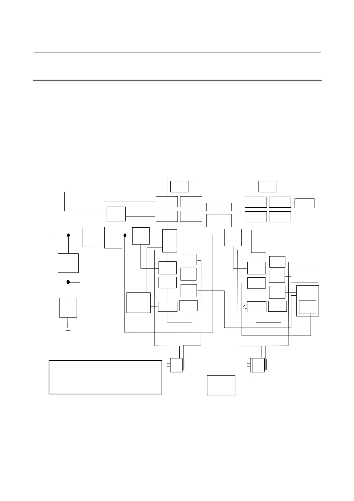
2.1
SVM1-4i AND SVM1-20i
This section shows an example of a 2-axis system configuration using
two SVM units which are the SVM1-4i or SVM1-20i.
In this example, a separated regenerative discharge unit is connected
but no external pulse generator is connected to the SVM unit for the
first axis (the unit nearer the CNC), while no separated regenerative
discharge unit is connected but an external pulse generator is
connected to the SVM unit for the second axis.
The servo check board adapter and servo check board in the
configuration example are provided for the first axis.
SVM1-4i or
SVM1-4i or
SVM1-20i
SVM1-20i
FUSE
FUSE
Stabilized
power supply
CXA19B
CXA19A
CXA19B
CXA19A
Battery
24 VDC
Servo check
case
board
CNC
JD1B
JD1A
JD1B
JD1A
Servo check
board adapter
3-phase : 200 to 240 VAC
1-phase : 220 to 240 VAC
Circuit
AC
Magnetic
CZ7
Magnetic
CZ7
breaker
line
contactor
contactor
filter
5 A
JF1
JF1
Circuit
breaker
CX29
CX29
JA34
JA34
External pulse
generator
CX30
CX30
JA72
Machine
JA72
operator’s
Separated
panel
regenerative
Lightning
Emergency
discharge
CXA20
CX5X
CXA20
CX5X
stop switch
surge
resistor
absorber
CAUTION
1 A circuit breakers, magnetic contactor, and AC line filter are
always required.
2 Use the stabilized 24VDC power supply for the βi SVM.
24 V power
24VDC power supply for the βi SVM and 24VDC power
supply for
supply for the motor brake cannot be shared.
motor brake
- 187 -
2.CONFIGURATION
I/O Link
B-65322EN/02
2.2
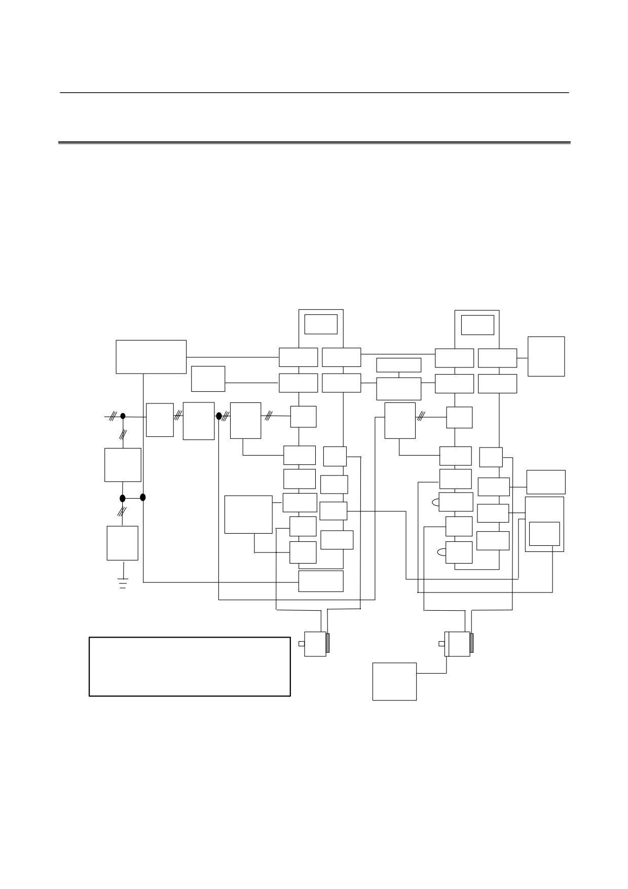
SVM1-40i AND SVM1-80i
This section shows an example of a 2-axis system configuration using
the SVM1-80i for the first axis (the unit nearer the CNC) and the
SVM1-40i for the second axis.
In this example, a separated regenerative discharge unit is connected
but no external pulse generator is connected for the first axis, while no
separated regenerative discharge unit is connected but an external
pulse generator is attached for the second axis.
The servo check board adapter and servo check board in the
configuration example are provided for the first axis.
SVM1-80i
SVM1-40i
FUSE
FUSE
Battery
Stabilized
case
power supply
CXA19B
CXA19A
CXA19B
CXA19A
24 VDC
Servo check
board
CNC
JD1B
JD1A
Servo check
JD1B
JD1A
board adapter
3-phase : 200 to 240 VAC
Circuit
AC
Magnetic
Magnetic
CZ4
CZ4
breaker
line
contactor
contactor
filter
5 A
CX29
JF1
CX29
JF1
Circuit
breaker
CX30
CX30
External
JA34
JA34
pulse
generator
CXA20
Machine
Separated
CXA20
regenerative
JA72
JA72
operator’s
discharge
panel
CZ5
CZ5
Emergency
resistor
Lightning
stop switch
CX5X
CX5X
surge
absorber
CZ6
CZ6
Fan unit
CAUTION
1 A circuit breakers, magnetic contactor, and AC line filter are
always required.
2 Use the stabilized 24VDC power supply for the βi SVM.
24 V
24VDC power supply for the βi SVM and 24VDC power
power
supply for the motor brake cannot be shared.
supply for
motor
- 188 -
B-65322EN/02
I/O Link
3.SPECIFICATIONS
3
SPECIFICATIONS
- 189 -
3.SPECIFICATIONS
I/O Link
B-65322EN/02
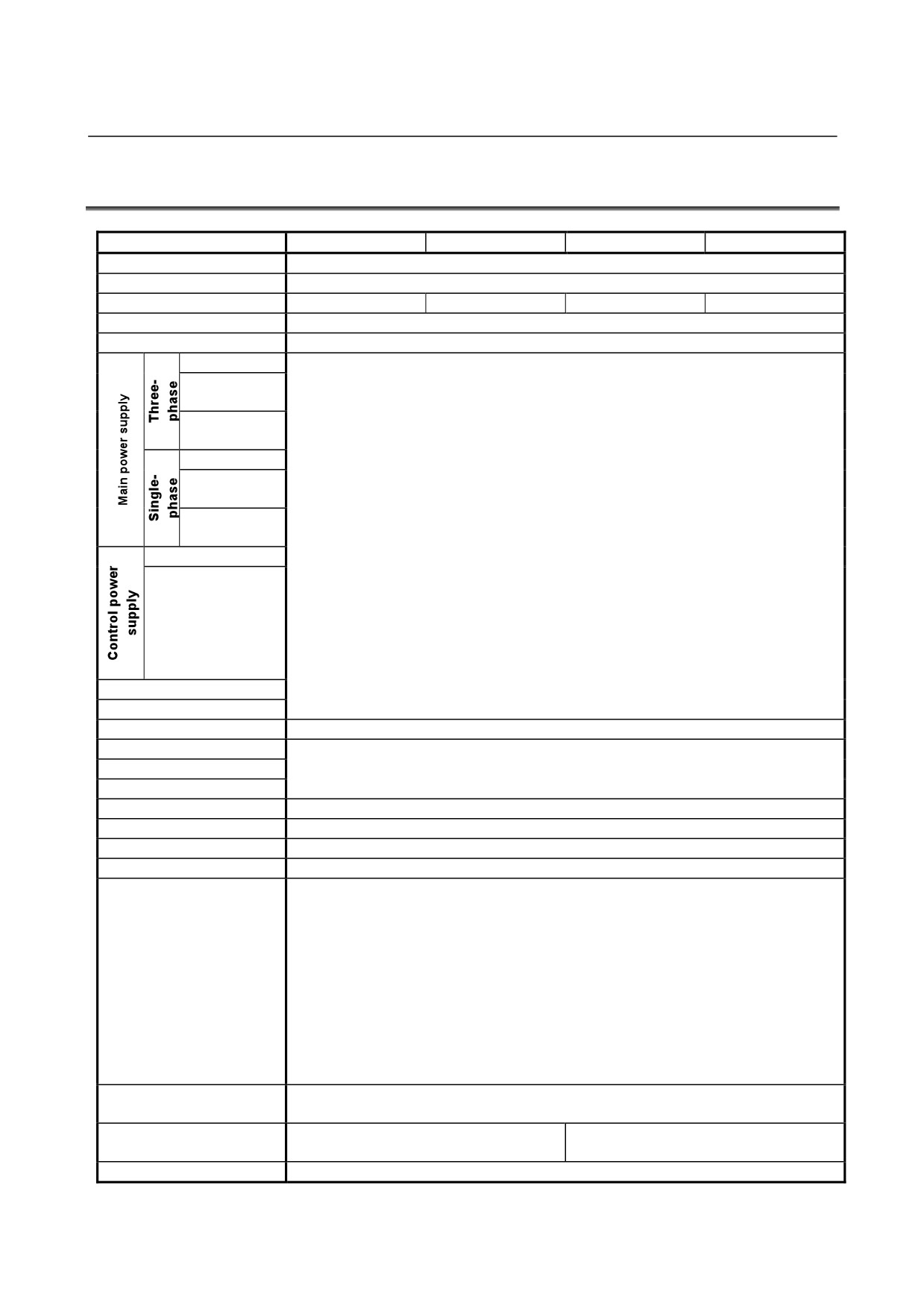
3.1
SPECIFICATIONS
Item
SVM1-4i
SVM1-20i
SVM1-40i
SVM1-80i
No. of controlled axes
1 axis
Interface with CNC
FANUC I/O Link
Unit drawing No.
A06B-6132-H001
A06B-6132-H002
A06B-6132-H003
A06B-6132-H004
Power PCB drawing No.
See Section 3.1 “SPECIFICATIONS” in Part I.
Control PCB drawing No.
A20B-8101-0200
Input voltage
Input current
(50Hz)
Power
supply rating
Input voltage
Input current
(50Hz)
Power
supply rating
See Section 3.1 “SPECIFICATIONS” in Part I.
Input voltage
Input current
Rated output current
Maximum output current
Servo HRV control
HRV2
Control method
Dynamic brake circuit
See Section 3.1 “SPECIFICATIONS” in Part I.
Output frequency range
External pulse input
Differential phase A/B, 1 ch
Internal DI
5 points (ESP, interlock, + overtravel, - overtravel, skip)
Setting display
Performed by master CNC via I/O Link
LEDs for status display
8 LEDs
-High Current
-IPM Abnormal
-High/Low Voltage of DC link
-Overheat of Discharge Resistor
-Low Voltage of Control Power Supply
Protection function
-I/O Link Communication Error
-Locked Fan Motor
-Disconnection of External Pulse Input
-Program or Setting Error
-Servo Motor Overheat
-Exceeding Stroke Limit
Ambient temperature
See Section 3.1 “SPECIFICATIONS” in Part I.
range
See Section 3.1 “SPECIFICATIONS” in
Weight
1.3kg
Part I.
Remarks
See Section 3.1 “SPECIFICATIONS” in Part I.
- 190 -

B-65322EN/02
I/O Link
3.SPECIFICATIONS
3.2
APPLICABLE MOTORS
See Section 3.2 “APPLICABLE MOTORS” in Part I.
3.3
SELECTING CIRCUIT BREAKER, MAGNETIC
CONTACTOR, AND AC LINE FILTER
3.3.1
Selecting Circuit Breaker
See Subsection 3.3.1, “Selecting Circuit Breaker” in Part I.
3.3.2
Selecting Magnetic Contactor
See Subsection 3.3.2, “Selecting Magnetic Contactor” in Part I. It is
recommended that one magnetic contactor be connected per βi SVM
unit.
3.3.3
Selecting AC Line Filter
See Subsection 3.3.3, “AC Line Filter” in Part I.
- 191 -
3.SPECIFICATIONS
I/O Link
B-65322EN/02
3.4
COOLING FAM MOTORS
3.4.1
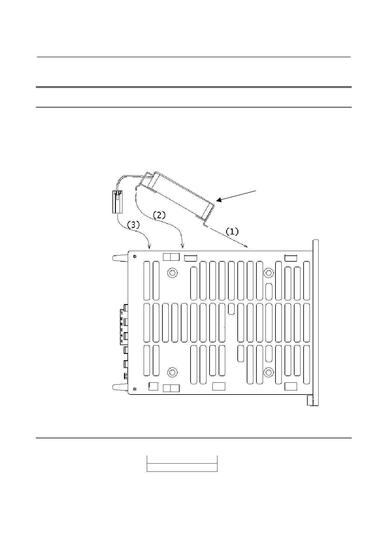
Installing the Cooling Fan Motor in the SVM1-4i and SVM1-20i
The SVM1-4i and SVM1-20i are supplied with a fan motor as
standard.
Install the fan motor in the order (1), (2), and (3) as illustrated below.
For an assembled diagram after the installation, see Subsection 8.1.1,
"SVM1-4i and SVM1-20i".
Cooling fan motor
3.4.2
SVM1-80i
For the SVM1-80i, the following cooling fan motor is required:
Ordering specification
A06B-6134-K002
- 192 -
B-65322EN/02
I/O Link
3.SPECIFICATIONS
3.5
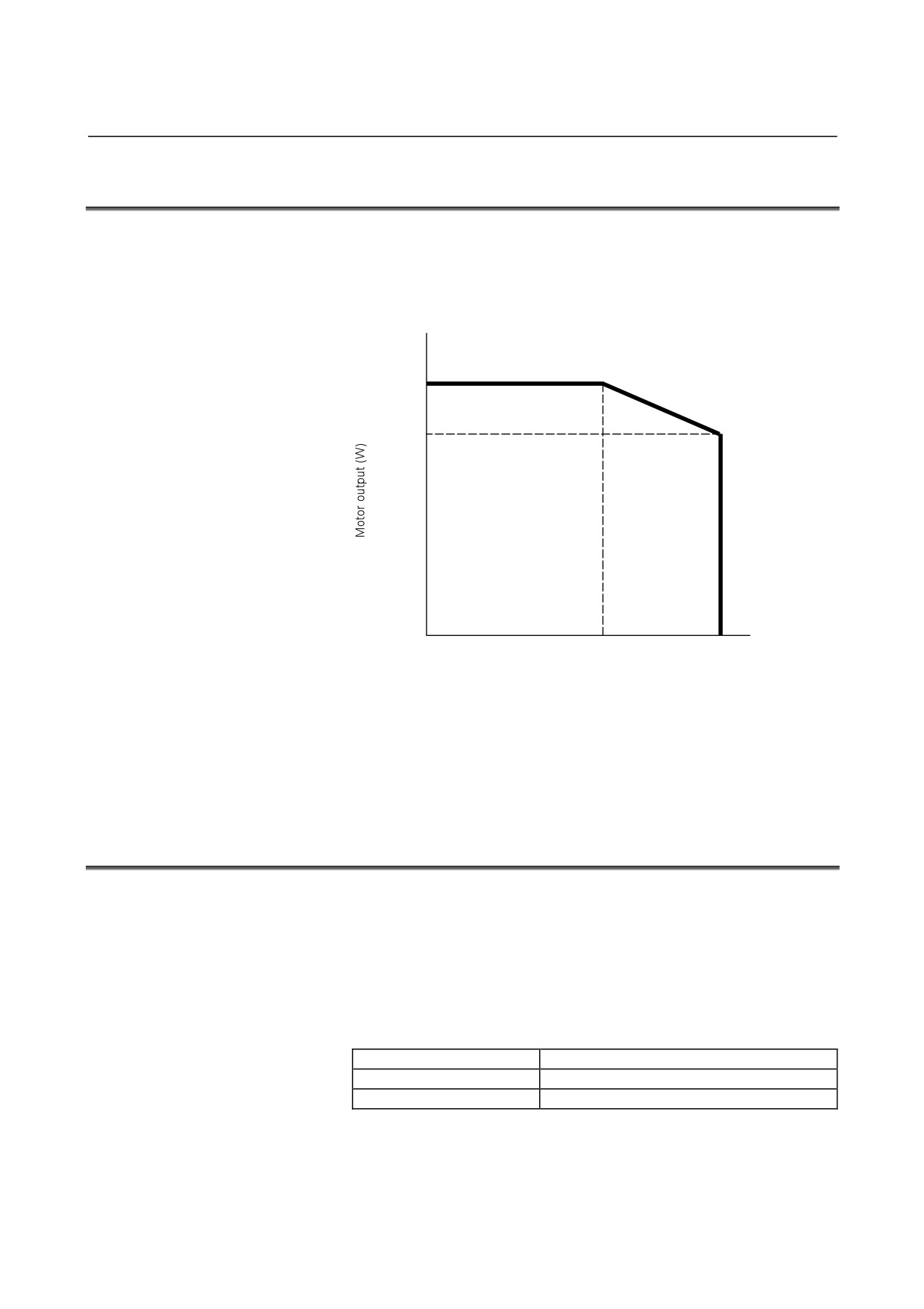
DERATING
Consider derating as shown below, according to ambient
temperatures.
SVM1-20i
Output derating for single-phase input
1200
900
0
0
35
55
Temperature (°C)
The SVM1-40i and SVM1-80i require current derating according to
the ambient temperature. For details, see the current derating
diagrams for the SVM1-40i and SVM1-80i in Section
3.5,
"DERATING" in Part I.
3.6
SEPARATED REGENERATIVE DISCHARGE RESISTOR
See Section
3.6 "SEPARATED REGENERATIVE DISCHARGE
RESISTOR" in Part I. In the description of Section 3.6, replace
Table 2.7.3 (a), "Regenerative discharge capacity of the regenerative
discharge resistor incorporated in servo amplifiers" with the
following:
Table 3.6.3(a) Regenerative discharge capacity of the regenerative
discharge unit incorporated in the βi SVM
βi SVM
Permissible regenerative energy amount
A06B-6132-H003
50W
A06B-6132-H004
130W
- 193 -
4.ORDERING INFORMATION
I/O Link
B-65322EN/02
4
ORDERING INFORMATION
See Chapter 4 “ORDERING INFORMATION” in Part I.
- 194 -
B-65322EN/02
I/O Link
5.POWER SUPPLY
5
POWER SUPPLY
- 195 -
5.POWER SUPPLY
I/O Link
B-65322EN/02
5.1
INPUT POWER SUPPLY
5.1.1
Three-phase Input Power Supply for Motor Power
See Subsection 5.1.1 “Three-phase Input Power Supply for Motor
Power” in Part I.
5.1.2
Single-phase Input Power Supply for Motor Power
See Subsection 5.1.2 “Single-phase Input Power Supply for Motor
Power" in Part I.
5.1.3
Control Power
Be sure to use a stabilized power supply as the 24-V power supply for
the βi SVM. The 24-V power supply for motor brakes cannot be
shared.
-
Nominal rated voltage: 24VDC
-
Allowable voltage fluctuation:
±10% (including momentary variations and ripples)
-
Power supply rating:
0.9 A (per βi SVM unit)
5.1.3.1
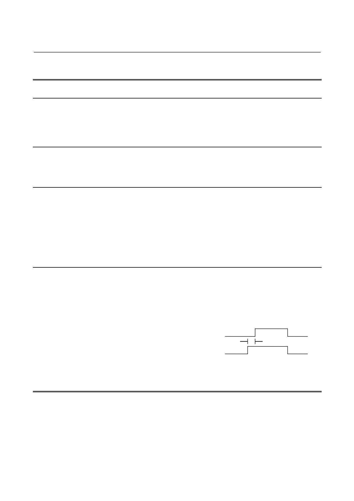
Sequence for turning on control power supply
Turn on the control power supply of the βi SVM at the same time
when the power to the host controller connected via the I/O Link is
turned on or before the host controller is turned on. When turning
off the power to the host controller, be sure to also turn off the control
power supply of the βi SVM.
Host controller power supply On
Off
βi SVM control power supply On
t
Off
t:
0 or more
5.2
POWER TRANSFORMER FOR EXPORTS
See Section 5.2 “POWER TRANSFORMER FOR EXPORTS" in Part
I.
- 196 -
B-65322EN/02
I/O Link 6.INSTALLATION CONDITIONS AND NOTES
6
INSTALLATION CONDITIONS AND
NOTES
See Chapter 6 “INSTALLATION CONDITIONS AND NOTES" in
Part I.
In the four figures shown in Section
6.4, "INSTALLING
LIGHTNING SURGE ABSORBERS", change the positions of the
magnetic contactor and AC line filter.
- 197 -