FANUC AC Servo Amplifiers βi Series. Description Manual (B-65322EN/02) - page 6
8.EXTERNAL DIMENSIONS / PANEL CUT-OUT DRAWINGS / MAINTENANCE AREA SVPM B-65322EN/02
8.3
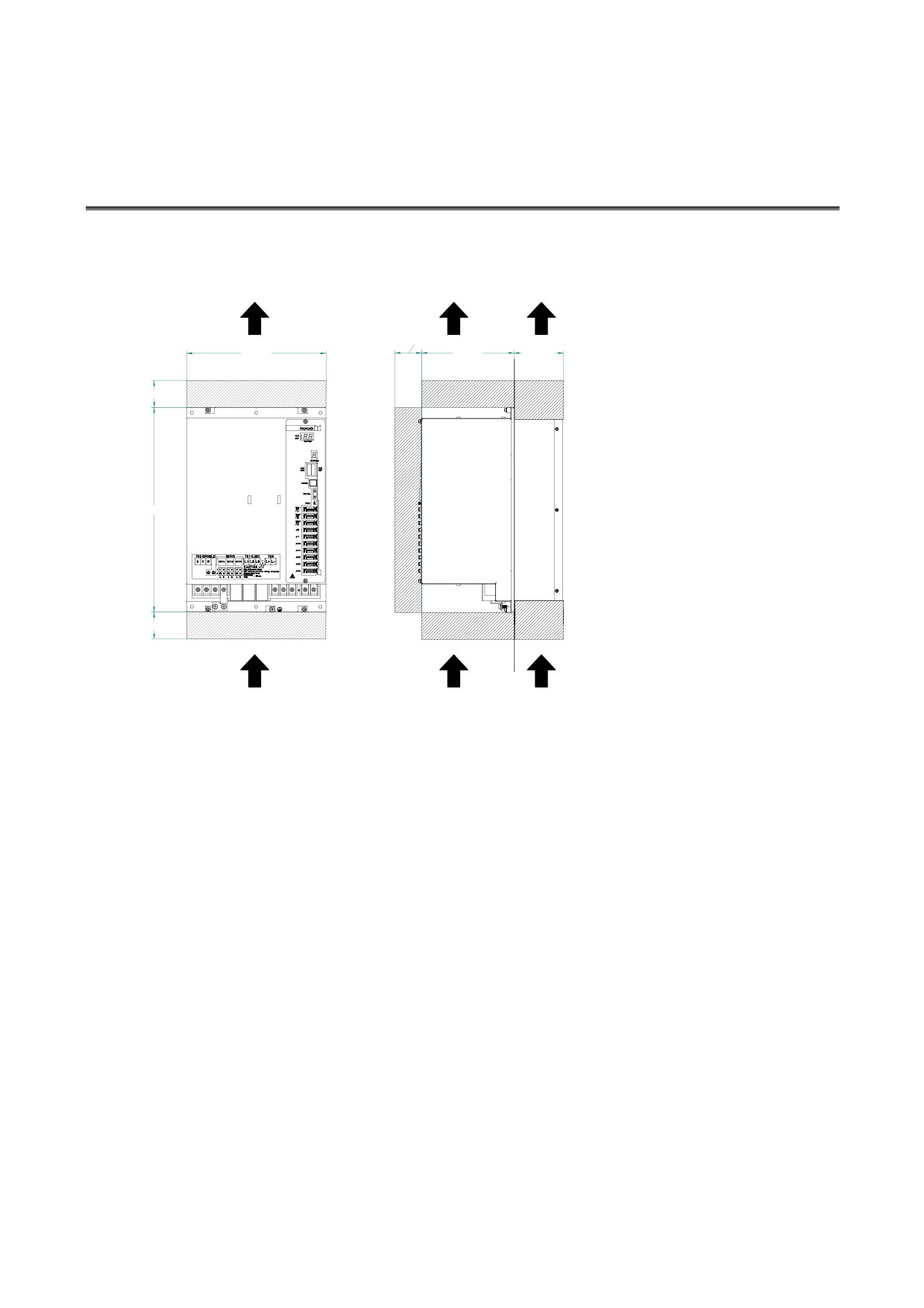
MAINTENANCE AREA
(1) When no fan unit is used
AIR FLOW
AIR FLOW
AIR FLOW
(Note)
㪌㪇 㫄㫄
㪉㪍㪇 㫄㫄
㪈㪎㪉 㫄㫄
㪐㪉㪅㪌 㫄㫄
㪌㪇 㫄㫄
㪊㪏㪇 㫄㫄
㪌㪇 㫄㫄
(NOTE) When a right-angle type cable
connector is used (+30 mm when a
straight type cable connector is used)
- 136 -
B-65322EN/02 SVPM 8.EXTERNAL DIMENSIONS / PANEL CUT-OUT DRAWINGS / MAINTENANCE AREA
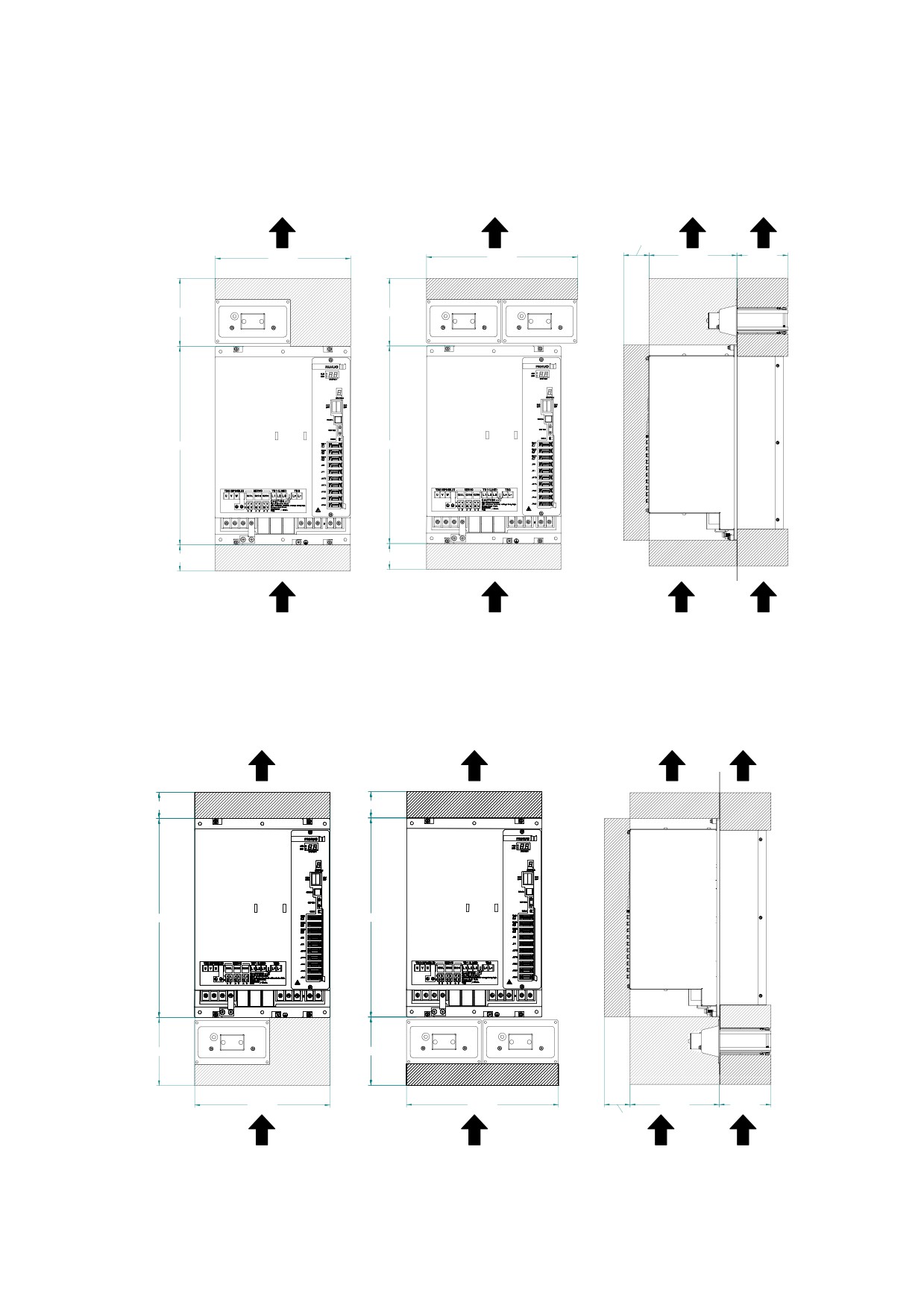
(2) When a fan unit used (placed on top of the servo amplifier)
AIR FLOW
AIR FLOW
AIR FLOW
AIR FLOW
(Note)
㪌㪇 㫄㫄
㪉㪍㪇 㫄㫄
㪉㪐㪉 㫄㫄
㪈㪎㪉 㫄㫄
㪈㪇㪇 㫄㫄
㪈㪊㪇 㫄㫄
㪈㪊㪇 㫄㫄
㪊㪏㪇 㫄㫄
㪊㪏㪇 㫄㫄
㪌㪇 㫄㫄
㪌㪇 㫄㫄
(NOTE) When a right-angle type cable
connector is used (+30 mm when a
straight type cable connector is used)
(3) When a fan unit used (placed below the servo amplifier)
AIR FLOW
AIR FLOW
AIR FLOW
AIR FLOW
㪌㪇 㫄㫄
㪌㪇 㫄㫄
㪊㪏㪇 㫄㫄
㪊㪏㪇 㫄㫄
㪈㪊㪇 㫄㫄
㪈㪊㪇 㫄㫄
㪉㪍㪇 㫄㫄
㪉㪐㪉 㫄㫄
㪈㪎㪉 㫄㫄
㪈㪇㪇 㫄㫄
(Note) 㪌㪇 㫄㫄
(NOTE) When a right-angle type cable
connector is used (+30 mm when a
straight type cable connector is used)
- 137 -
8.EXTERNAL DIMENSIONS / PANEL CUT-OUT DRAWINGS / MAINTENANCE AREA SVPM B-65322EN/02
8.4
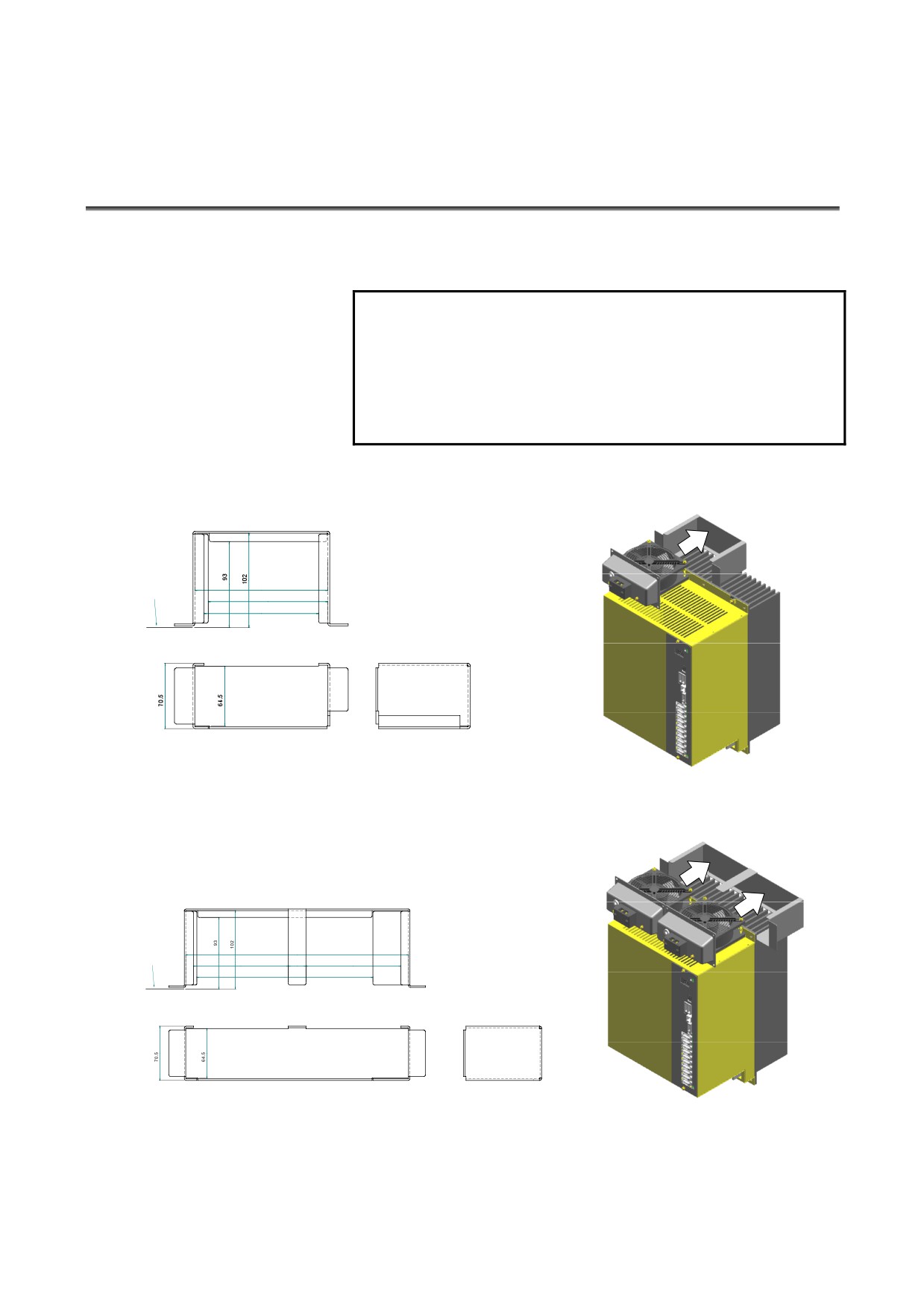
DUCT
Shown below is an example duct structure where a FANUC fan unit
(A06B-6134-K001) is used.
NOTE
1 Install a duct having the shape shown below
between the fan unit and heat sink to provide a
ventilation flue.
2 Weld the duct to the cabinet.
3 If the fan unit is placed below the servo amplifier, no
duct is needed.
(1) When one fan unit is used
Panel cut-out
144
plane
129.5
124
(2) When two fan units are used
Panel cut-out
291
plane
124
23
124
230
- 138 -
B-65322EN/02 SVPM 8.EXTERNAL DIMENSIONS / PANEL CUT-OUT DRAWINGS / MAINTENANCE AREA
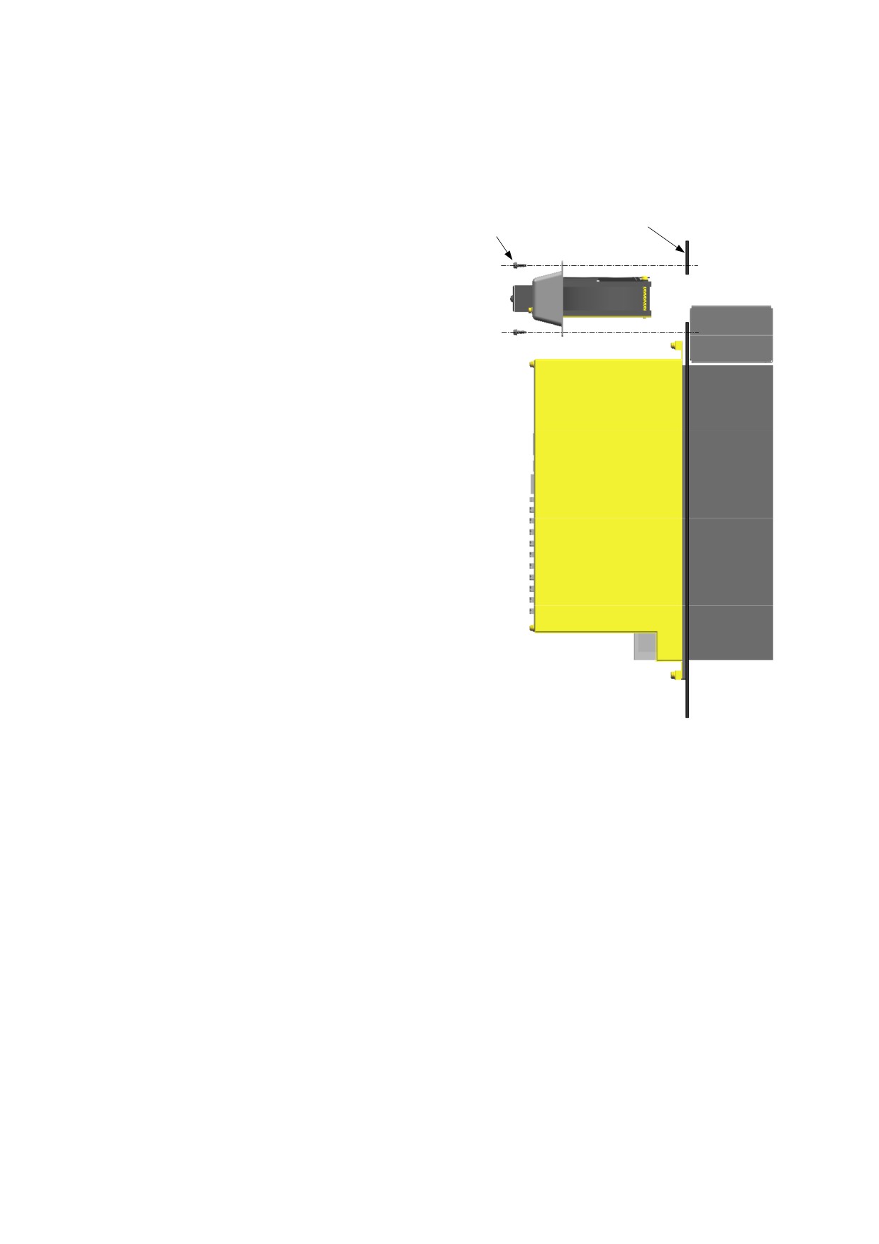
How to mount a fan unit (A06B-6134-K001)
Panel cut-out plane
4 screws - M4 × 10
200VAC IN
Applicable wire 1.25mm2
Applicable crimp terminal 1.25-4
- 139 -
9.TOTAL CONNECTION DIAGRAM
SVPM
B-65322EN/02
9
TOTAL CONNECTION DIAGRAM
9.1
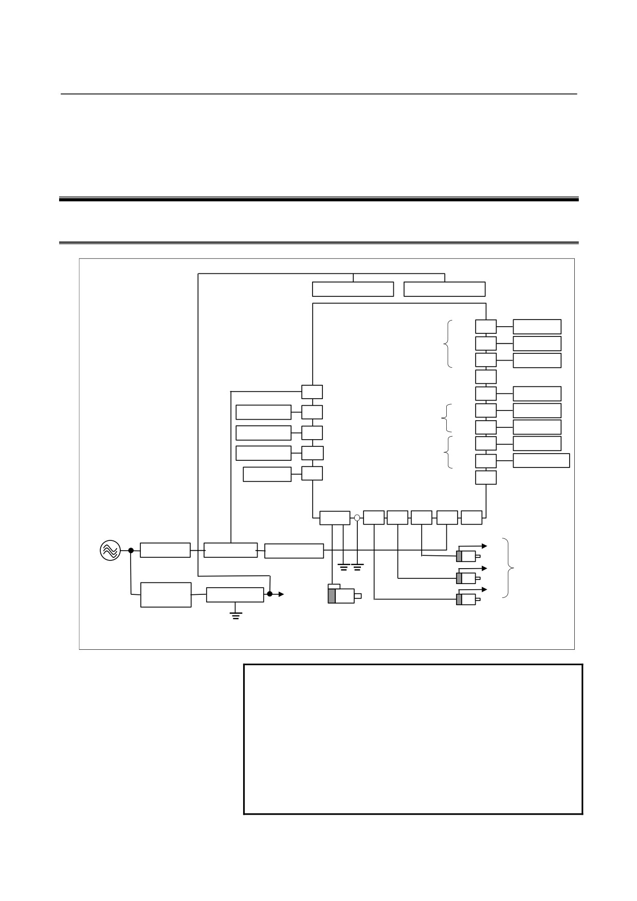
CONNECTION DIAGRAM
Fan unit
Fan unit
SVPM
JF1
K22
Servo Motor
Pulse Coder I/F
JF2
K22
Servo Motor
JF3
K22
Servo Motor
JX6
K6
CX3
JY1
K33
LM, SM, OVR
JA7A
CNC
Emergency stop
K7
CX4
K12
Spindle I/F
JA7B
K12
CNC
CXA2C
24V power supply
K69
*1
JYA2
K14
Spindle Motor
Battery
K28
CX5X
Spindle Sensor
JYA3
K16
Position Coder
CNC
K27
COP10B
JYA4
(FSSB I/F)
TB2
CZ2L
CZ2M CZ2N
TB1
TB3
Flange
K10
K21
K21
K21
K1
200-240VAC
K70
K70
JF3
Circuit breaker 1
Magnetic contactor
AC reactor
JF2
Pulse Coder I/F
G
G
Circuit breaker 2
JF1
Lightning surge
Power
5A
b
b
supply for
Spindle
Servo
Motor
Motor
G
*1 K14 is for the Mi sensor. For the MZi sensor, K17 is used.
NOTE
1 Always install the circuit breakers, magnetic
contactor, and AC reactor.
2 To protect the equipment from lightning surge
voltages, install a lightning surge absorber across
each pair of power lines and across each power line
and the grounding line at the power inlet of the
power magnetics cabinet.
3 Be sure to connect the grounding terminal (G) on
TB2 to a substantial ground.
- 140 -
B-65322EN/02
SVPM
9.TOTAL CONNECTION DIAGRAM
9.2
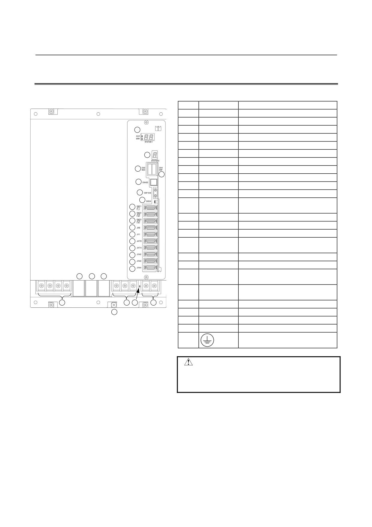
CONNECTOR LOCATION
No.
Name
Remarks
1
STATUS1
Status LED : spindle
2
STATUS2
Status LED : servo
1
3
CX3
Main power MCC control signal
4
CX4
Emergency stop signal (ESP)
5
CXA2C
24VDC power input
2
6
COP10B
Servo FSSB I/F
7
CX5X
Absolute Pulsecoder battery
3
8
JF1
Pulsecoder : L axis
4
9
JF2
Pulsecoder : M axis
5
10
JF3
Pulsecoder : N axis
6
11
JX6
Power outage backup module
7
Load meter, speedometer, analog
8
12
JY1
override
9
13
JA7B
Spindle interface input
10
11
14
JA7A
Spindle interface output
12
15
JYA2
Spindle sensor Mi, MZi
13
α position coder
14
16
JYA3
External one-rotaion signal
15
17
JYA4
(Unused)
16
18
TB3
DC link terminal block
17
DC link charge LED
21
22
23
19
(Warning)
Main power supply cnnection terminal
20
TB1
board
24
20
19
18
21
CZ2L
Servo motor power line : L axis
25
22
CZ2M
Servo motor power line : M axis
23
CZ2N
Servo motor power line : N axis
24
TB2
Spindle motor power line
25
Tapped hole for grounding the flange
WARNING
Do not touch any component in the
module or any connected cable when
LED 19 is on, because it is dangerous.
- 141 -
9.TOTAL CONNECTION DIAGRAM
SVPM
B-65322EN/02
9.3
DETAILED DESCRIPTONS OF CONNECTIONS
9.3.1
Common
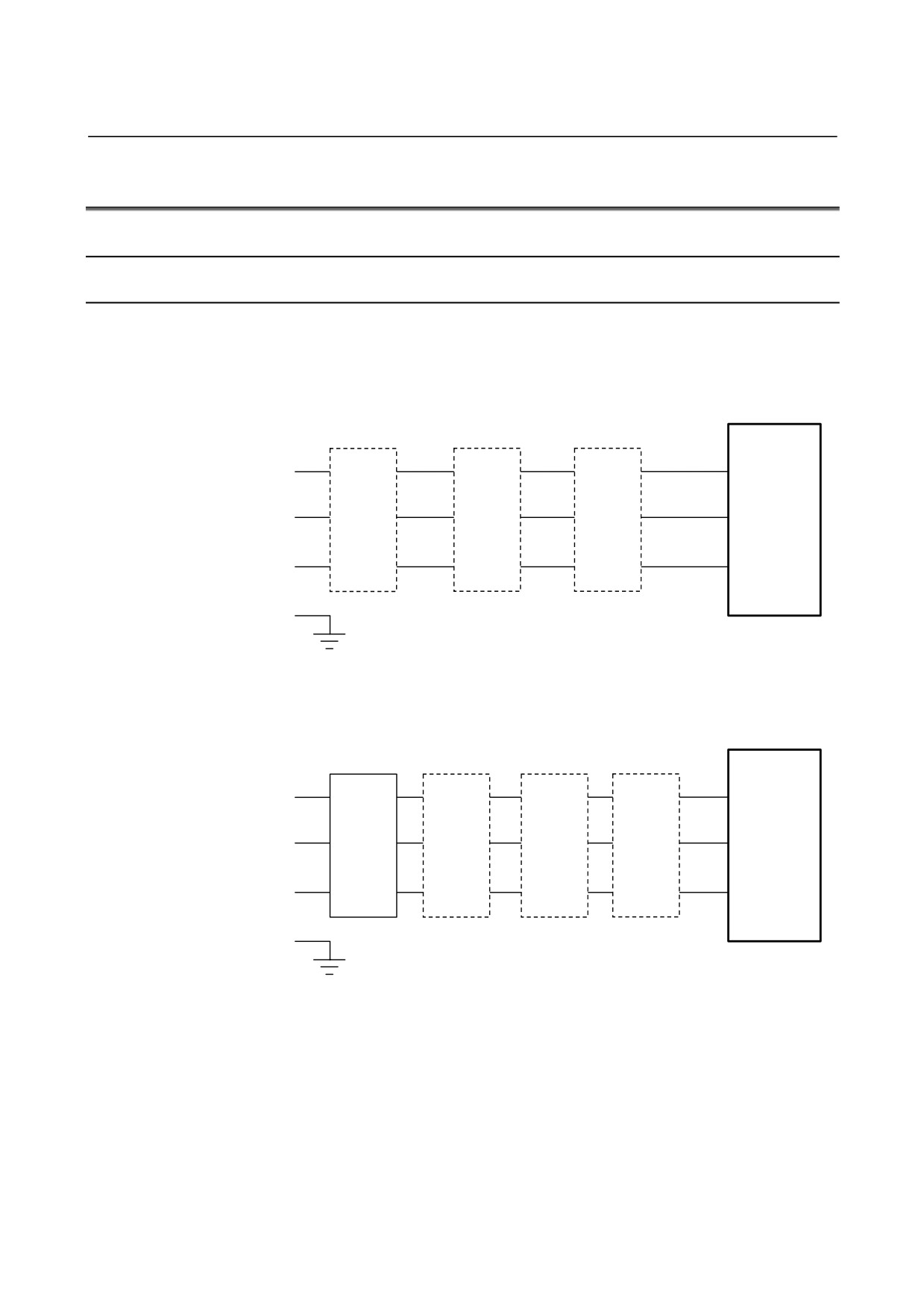
9.3.1.1 Details of cable K1
Cable K1 is used to supply main power to the SVPM.
(1) Configuration
(a) For a power supply voltage of 200 to 240 VAC
TB1
SVPM
L1
R
(L1)
Main power
Circuit
Magnetic
AC
supply
breaker 1
contactor
reactor
L2
200 VAC
S
(L2)
to
240 VAC
L3
T
(L3)
50/60 Hz
G
(b) For a power supply voltage of
400 to
480 VAC (an
insulating transformer is needed)
TB1
SVPM
L1
R
(L1)
Main power
Insulating
Circuit
Magnetic
AC
supply
power
breaker 1
contactor
reactor
L2
400 VAC
S
supply
(L2)
to
transformer
480 VAC
L3
T
(L3)
50/60Hz
G
- 142 -
B-65322EN/02
SVPM
9.TOTAL CONNECTION DIAGRAM
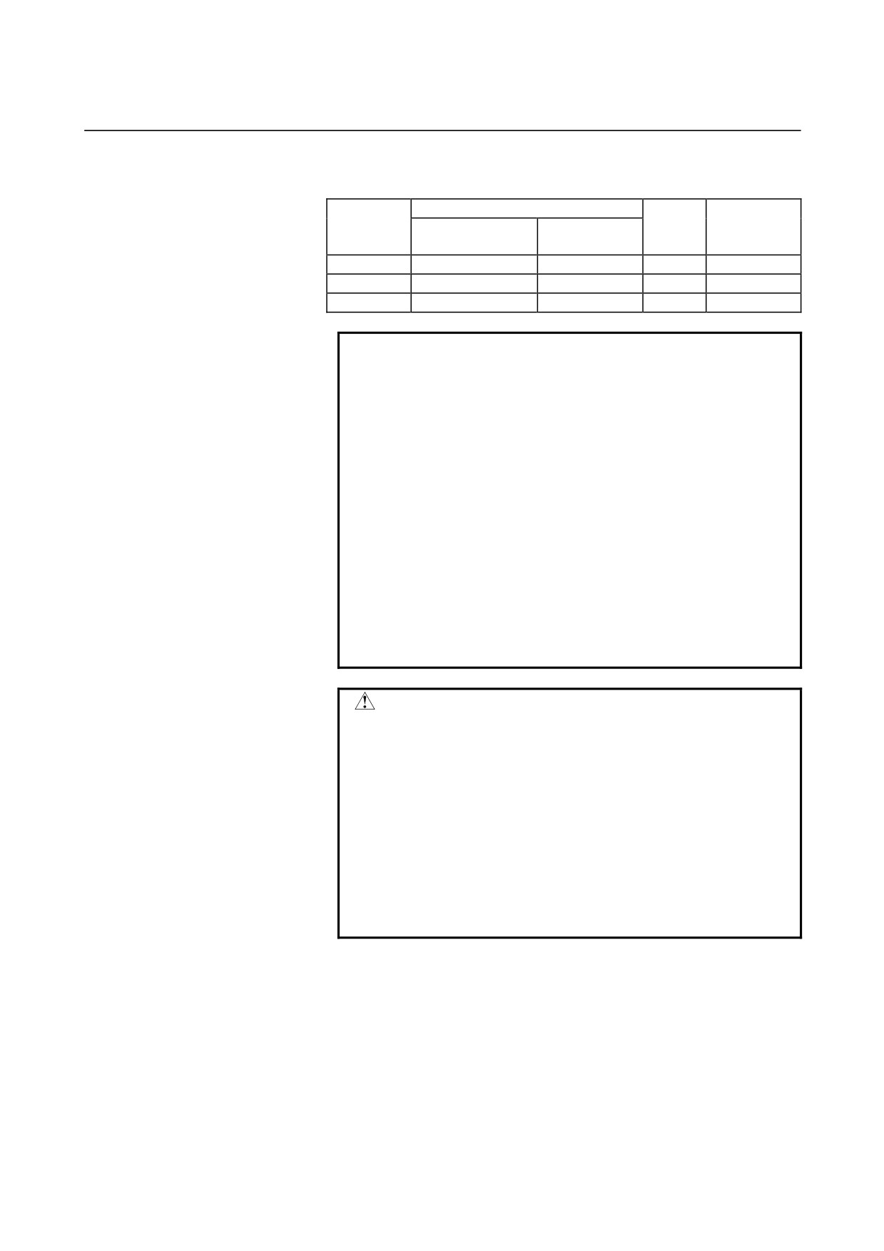
(2) Cable specifications
Applicable cable
Terminal
Tightening
Model
Heavy-duty power
Heat-resistant
screw
torque
cable (Note 1)
cable (Note 2)
SVPM*-5.5i
5.5 mm2 or more
5.5 mm2 or more
M5
2.0 to 2.5 N⋅m
SVPM*-11i
8 mm2 or more
8 mm2 or more
M5
2.0 to 2.5 N⋅m
SVPM*-15i
14 mm2 or more
14 mm2 or more
M5
2.0 to 2.5 N⋅m
NOTE
1
Four-conductor polyvinyl heavy-duty power cable
(JIS C3312) (VCT : heat-resistant 60 °C)
2
Fire-retardant polyflex wire (heat-resistant 105 °C)
or equivalent to LMFC manufactured by The
Furukawa Electric Co., Ltd.
3
The cross-section area of each cable is determined
under the following conditions:
(1) At SVPM rated output
(2) Environment temperature of cable : 30°C
(3) Number of harnesses
3 (No current flows through the ground wire
during normal operation.)
The required cross-section area of a cable varies
depending on the environment and requirements of
the user. Select an appropriate cable size.
WARNING
1
Defects, such as a loose screw, an incorrectly
inserted connector, and a poorly crimped terminal,
can lead to a motor malfunction, excessive heat
generation, and a ground fault. Exercise
adequate care in installing servo amplifiers.
2
A loose screw and a poorly crimped terminal (or, if
a connector is used, a loose connector contact or
an incorrect connector pin-to-cable connection) on
high-current carrying power supply wires or motor
power wires can lead to fire. Exercise adequate
care in wiring.
- 143 -
9.TOTAL CONNECTION DIAGRAM
SVPM
B-65322EN/02
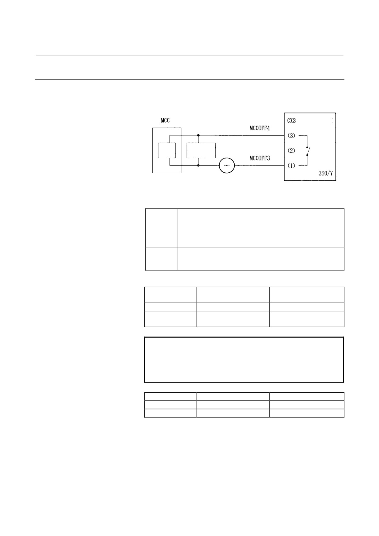
9.3.1.2 Details of cable K6
Cable K6 is used to control the magnetic contactor if it is installed
outside the unit.
SVPM
Coil
Spark
Internal
killer
contact
External power supply
(must match the coil voltage of the
user's equipment)
Connector
Manufactured by Tyco Electronics AMP
D-3200 series
Housing
2-178128-3
(1 pcs.)
Contact
1-175218-2
(2 pcs.)
(FANUC ordering information: A06B-6134-K201)
Cable
Two-conductor polyvinyl heavy-duty power cable (JIS C3312),
conductor size of 1.25 mm2 (50/0.18), PVC sheath 9.6 mm in
diameter
Internal-contact specification:
Resistive load
Inductive load
(cosφ=1)
(cosφ=0.4, L/R=7msec)
Rated load
250VAC, 5A / 30VDC, 5A
250VAC, 2A / 30VDC, 2A
Maximum contact
5A
5A
rating
NOTE
Always install a spark killer (CR) that matches the
magnetic contactor to protect the internal contacts.
The following table lists the recommended
capacitances and resistances.
Coil voltage
C
R
24 VDC
0.22 µF
22 Ω
100 to 230 VAC
0.1 µF
220 Ω
- 144 -
B-65322EN/02
SVPM
9.TOTAL CONNECTION DIAGRAM
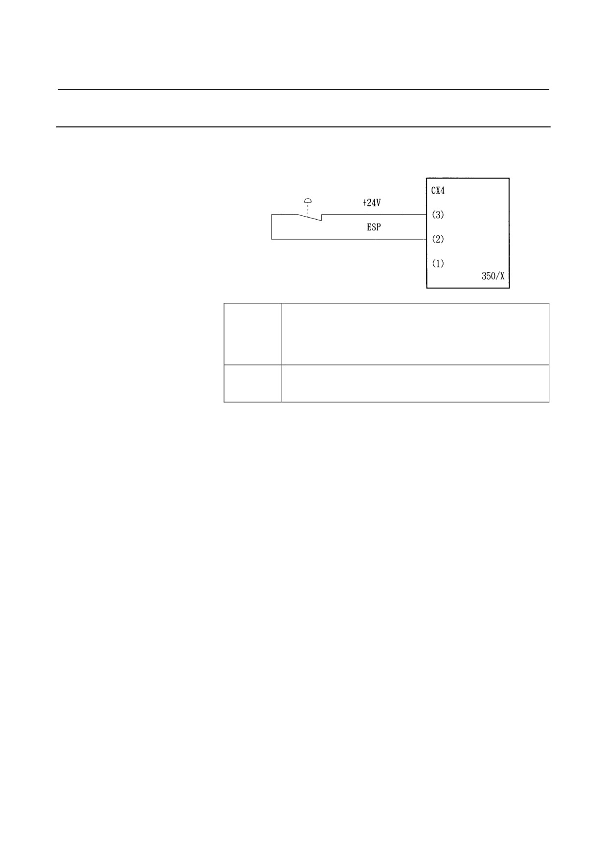
9.3.1.3 Details of cable K7
Cable K7 is used to supply an emergency stop signal to the SVPM.
Emergency stop
contact
SVPM
Connector
Manufactured by Tyco Electronics AMP
D-3200 series
Housing
1-178128-3
(1 pcs.)
Contact
1-175218-2
(2 pcs.)
(FANUC ordering information: A06B-6134-K201)
Cable
Two-conductor polyvinyl heavy-duty power cable (JIS C3312),
conductor size of 1.25 mm2 (50/0.18), PVC sheath 9.6 mm in
diameter
(1)
When the contact is ON (closed), the spindle motor and servo
motor are enabled.
When the contact is OFF (open), the external magnetic contactor
(MCC) is in the off state, and the spindle motor and servo motor
do not operate.
(2)
When the contact is set to OFF (open) during motor rotation, the
spindle motor decelerates, then stops, and the servo motor is
stopped by the dynamic brake.
(3)
The contact input signal is specified as follows:
<1> As the external contact capacity, a voltage of at least 30
VDC and a current of at least 100 mA are required.
<2> Significant levels
(with the voltage between input pins)
when the contactless signal input mode is used:
Low level "logic 0": Up to 2 V
High level "logic 1": At least 20 V
(4)
When the SVPM main power is turned off for safety in such a
case that the machine protection door is open, the contact of the
ESP signal (CX4), which is input to the SVPM, must be set to
OFF (open) within 200 ms after turn-off of the SVPM main
power.
When the contact of the ESP signal (CX4) remains ON (closed)
after the SVPM main power is turned off, a DC link low-voltage
alarm occurs in the SVPM.
- 145 -
9.TOTAL CONNECTION DIAGRAM
SVPM
B-65322EN/02
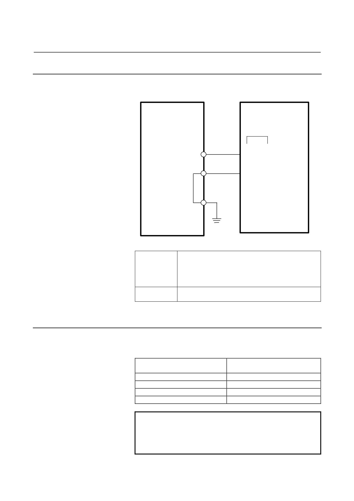
9.3.1.4 Details of cable K69
Cable K69 is used to supply control power (+24 V) to the SVPM.
+24V power
SVPM
supply unit
CXA2C
K69
24V
(A1) 24V
0V
(A2) 0V
Connector
Manufactured by Tyco Electronics AMP
D-2100 series
Housing
1-1318119-4
(1 pcs.)
Contact
1318107-1
(2 pcs.)
(FANUC ordering information:A06B-6134-K201)
Cable
Conductor size : 0.5mm2, AWG20
Instruction outer diameter : 1.11-1.87 mm
9.3.1.5 Details of cable K70
Cable K70 is used to ground the SVPM.
Grounding cable conductor diameter
Motor power cable cross-section S
Grounding cable cross-section
(mm2)
(mm2)
S ≤ 5.5
5.5 or greater
5.5 < S ≤ 16
S or greater
16 < S ≤ 35
16 or greater
35 < S
S/2 or greater
NOTE
The following M5 crimp terminal can be used with a
cable having a large conductor diameter.
Nichifu Co., Ltd. CB22-5S
Overall conductor size range : 16.78 to 22.66 mm2
- 146 -
B-65322EN/02
SVPM
9.TOTAL CONNECTION DIAGRAM
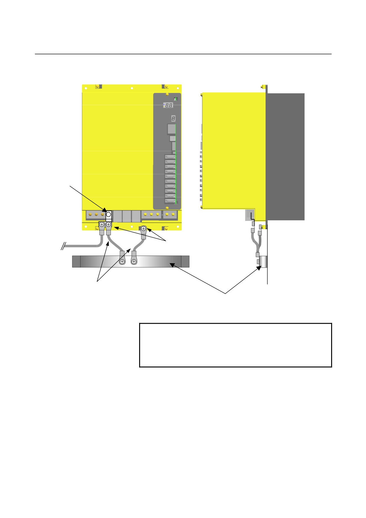
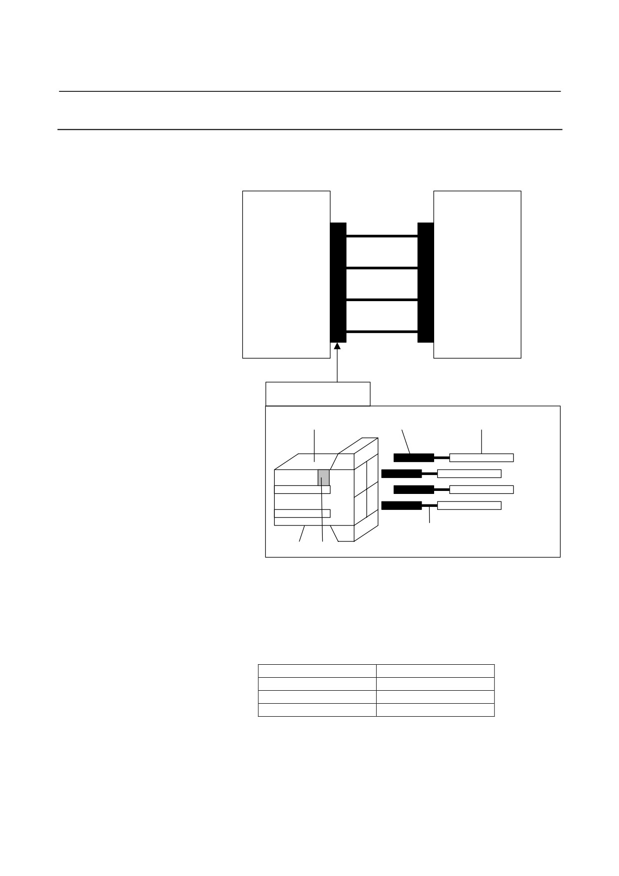
(Grounding example with K70)
L-shaped
metal plate
(TB2
grounding
terminal)
From spindle power line
K70
M5 screw
K70
Use short cable.
Ground plate of cabinet
(To be connected to system ground)
NOTE
Securing cables (crimp terminals) to the ground
terminal together is not permitted.
As shown in the above figure, attach one cable
(crimp terminal) to each screw.
- 147 -
9.TOTAL CONNECTION DIAGRAM
SVPM
B-65322EN/02
9.3.1.6 Details of cable K21
The cable K21 is a power cable used between the SVPM and motor.
The cable is attached to the SVPM through the connector D-5000.
SVM
Motor
CZ2 (B1)
U
U
CZ2 (A1)
V
V
CZ2 (B2)
W
W
CZ2 (A2) GND
GND (Body)
Connector D-5000
Receptacle housing Receptacle contact
Cable
A2 (GND)
A2
B2
B2 (W)
G
2
W
A1 (V)
A1
B1
V
B1 (U)
1
U
A
B
Conductor
Key Indication of the key type
• About the receptacle housing of the SVPM-side connector
The SVPM-side connector is a key type. The key is intended to
prevent incorrect connection between the axes. Select the
receptacle housing that matches the SVPM and its axis that are to
be used.
Specification of the key
Applicable SVPM
XX
CZ2L
XY
CZ2M
YY
CZ2N
• About the receptacle contact of the SVPM-side connector
Four types receptacle contacts are prepared for the different line
diameter of the cable. Please use the receptacle contact which
suits the line diameter of the cable.
- 148 -
B-65322EN/02
SVPM
9.TOTAL CONNECTION DIAGRAM
• About the cable specification
Select the cable specification by considering the following
conditions for use.
<1> Motor current rating or current needed in use on a real
machine
<2> Cable type (heat resistance temperature, etc.)
<3> Environment in which the cable is installed
(operating
ambient temperature, etc.)
<4> Need of water proofing (pay attention to the diameter of the
applicable cable clamp)
<5> Certification for CE marking
(compliance with various
safety standards and EMC standard)
<6> Securing insulation space among the cable pins at the time
of cabling
• About the motor-side connector
The specification of the motor-side connector varies from one
motor model to another.
Refer to "FANUC AC SERVO MOTOR βis series Descriptions
(B-65302EN)" for explanations about the specification of the
motor-side connector.
- 149 -
9.TOTAL CONNECTION DIAGRAM
SVPM
B-65322EN/02
9.3.1.7 Details of cable K22
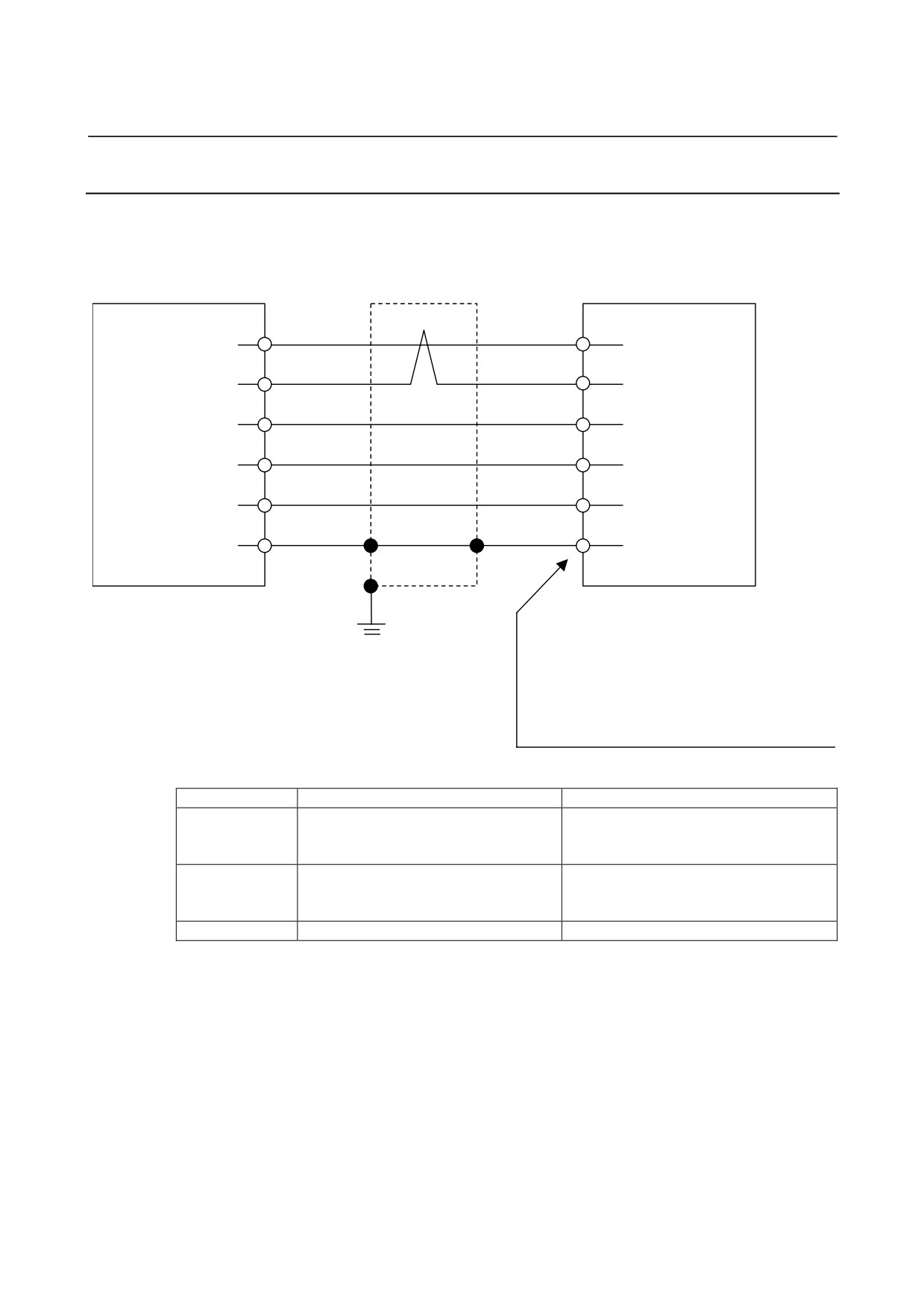
The cable K22 is used to connect the SVPM and Pulsecoder.
For servo motor βis series (β2/4000is to β22/2000is)
Shield
SVPM
Servo motor
(5)
RD
(6)
(6)
*RD
(5)
(9, 20)
5V
(8, 9)
(12, 14)
0V
(7, 10)
(7)
6V
(4)
(16)
Drain wire
FG
(3)
20-pin half-pitch connector
Connector (Japan Aviation Electronics Industry)
Ground plate
JN2x S10SL1 : for φ5.7 to 7.3 sheath diameter
JN2x S10SL2 : for φ6.5 to 8.0 sheath diameter
D : Straight plug
F : Angle plug
Contact (Japan Aviation Electronics Industry)
JN1-22-22S
Using cable conductor
Signal name
Cable length : 28m or less
Cable length : 50m or less
0.3mm2 × 5 (Note 4)
0.5mm2 × 5 (Note 4)
5V, 0V, 6V
Wire construction 12/0.18 or 60/0.08
Wire construction 20/0.18 or 104/0.08
Insulation outer diameter φ0.8 to φ1.5
Insulation outer diameter φ0.8 to φ1.5
0.18mm2 or more
0.18mm2 or more
RD, *RD
Twisted-pair wire
Twisted-pair wire
Insulation outer diameter φ0.8 to φ1.5
Insulation outer diameter φ0.8 to φ1.5
Drain wire
0.15mm2 or more
0.15mm2 or more
See Subsection 5.4.1 for explanations about the SVPM-side connector
that matches the recommended cable.
- 150 -
B-65322EN/02
SVPM
9.TOTAL CONNECTION DIAGRAM
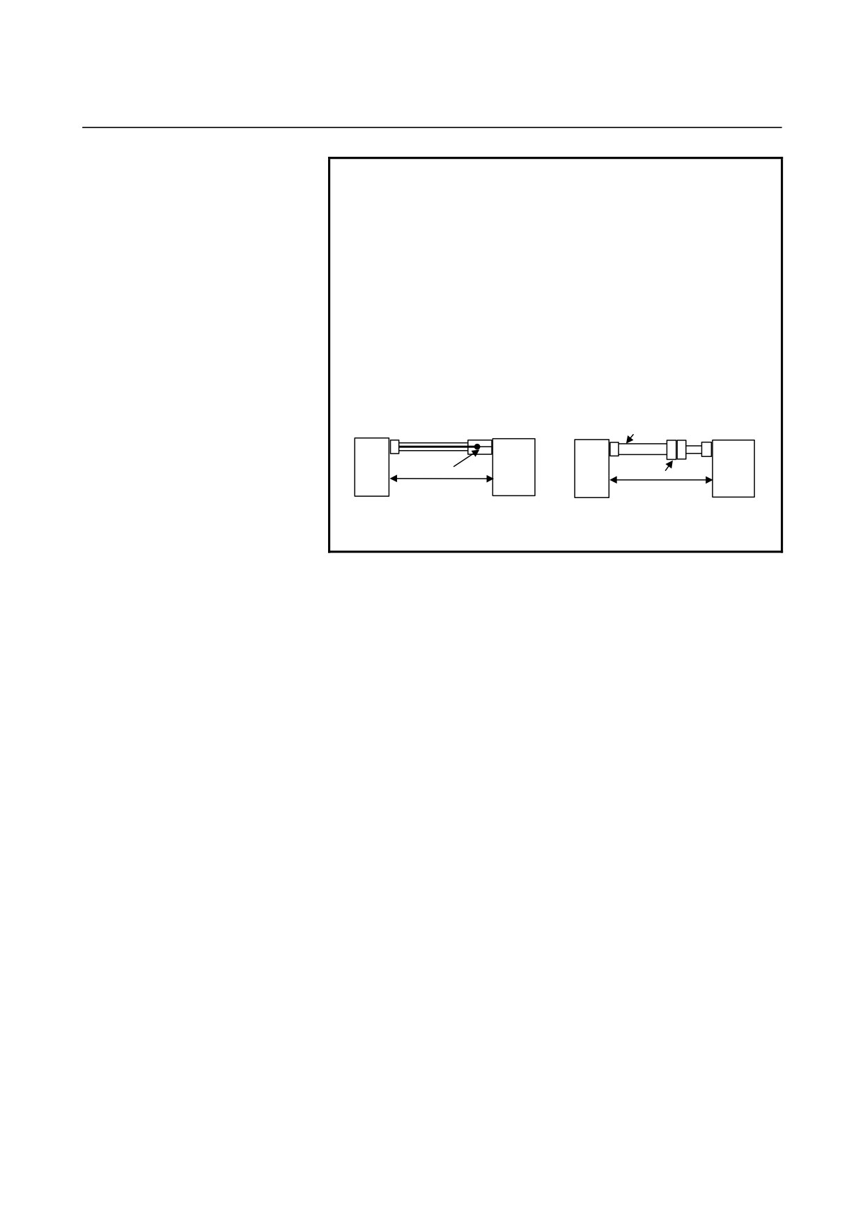
NOTE
1 The ground plate to which the shield is connected
must be placed as close as possible to the servo
amplifier so that distance between the ground plate
and the servo amplifier becomes shortest.
2 In case that the cable is prepared by MTB, total
resistance of 5V and 0V must be less than 2Ω.
3 Pulsecoder side connector can accept maximum
0.5mm2 (wire construction 20/0.18 or 104/0.08,
diameter φ1.5 or less) wire and sheath diameter is
φ5.7 to φ8.0. In case of using thicker wire or cable,
take measures described below.
[Case 1] Cable conductor exceeds 0.5mm2 .
[Case 2] Sheath diameter of exceeds φ8.
SVM
Servo motor
SVM
Cable thicker than φ8
Servo motor
Soldering or crimping
Connector
The total resistance (Round
The total resistance (Round
trip) of 5 V and 0 V must be
trip) of 5 V and 0 V must be
less than 2Ω.
less than 2Ω.
4 In case of incremental Pulsecoder, 6V is not
necessary to be connected.
• Crimp tool specification
A06B-6114-K201/JN1S : For 0.3 mm2
A06B-6114-K201/JN1L : For 0.18 mm2 or 0.5 mm2
• Connector kit specification
A06B-6114-K204/S : Straight plug (including a contact)
A06B-6114-K204/E : Elbow plug (including a contact)
•
Recommended cable
A66L-0001-0460 : Flexible cable 28m or less long
A66L-0001-0462 : Flexible cable 50m or less long
A66L-0001-0481 : Fixed cable 28m or less long
A66L-0001-0491 : Fixed cable 50m or less long
- 151 -
9.TOTAL CONNECTION DIAGRAM
SVPM
B-65322EN/02
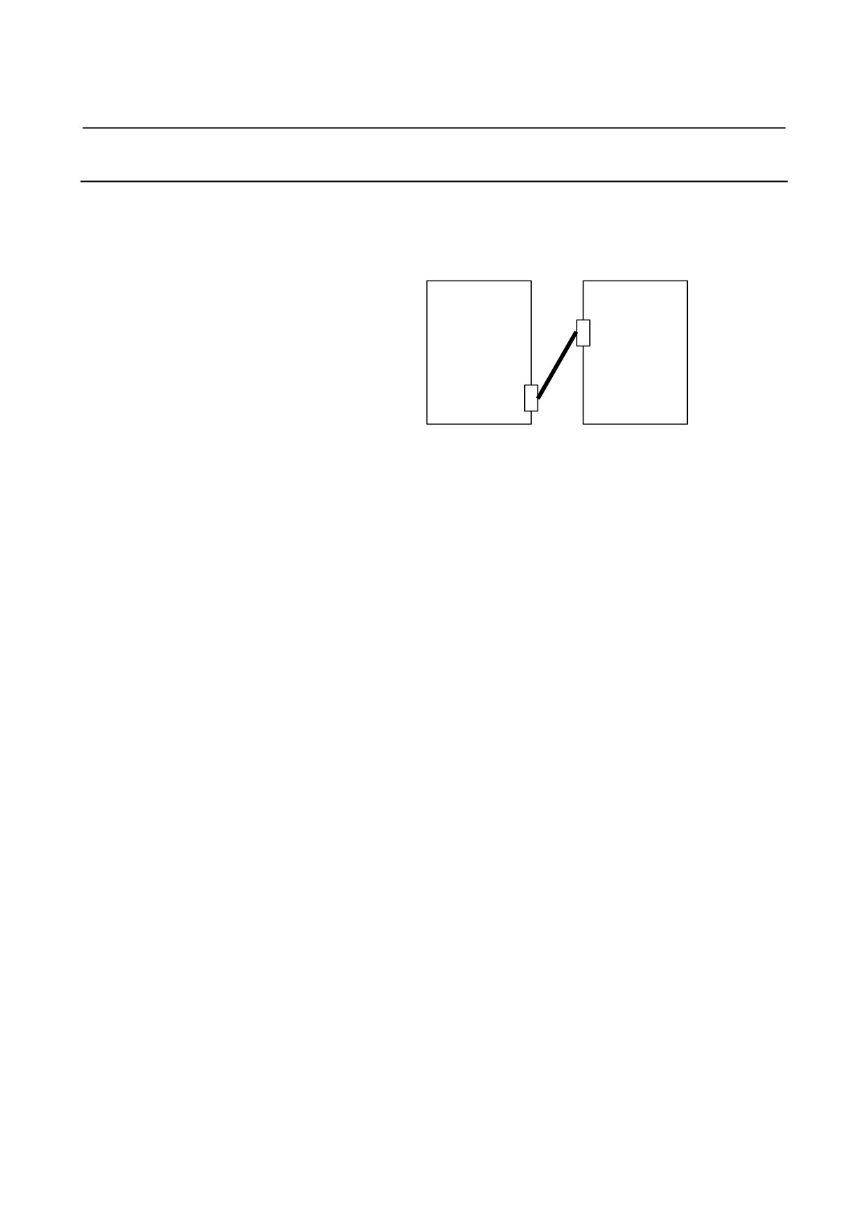
9.3.1.8 Details of cable K27
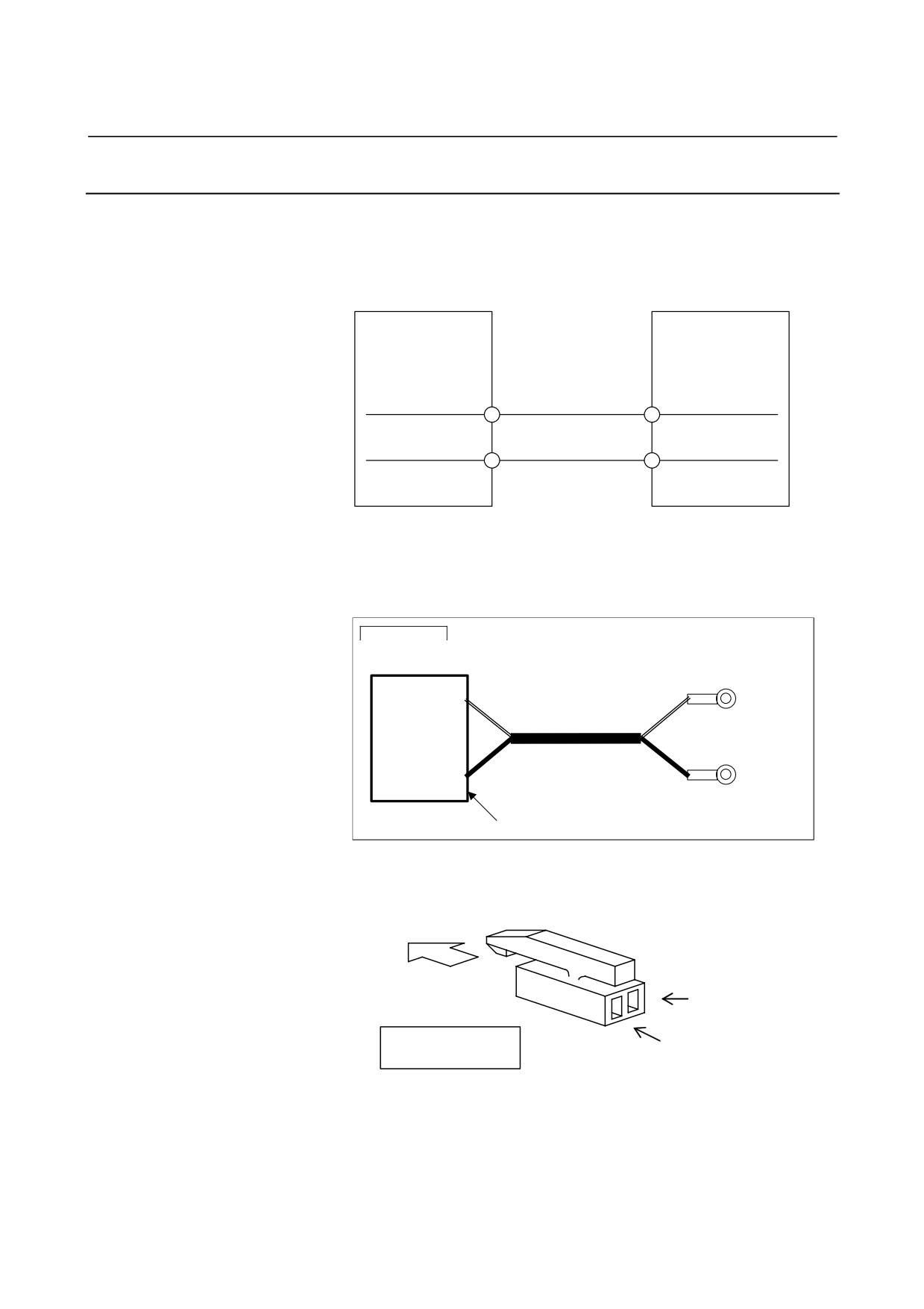
Cable K27 is an optical fiber cable used in the FSSB interface.
CNC
SVPM
COP10B
K27
COP10A
•
The cable is run from connector COP10A to connector COP10B
in the SVPM.
• Refer to the applicable CNC connection manual for detailed
specifications of the optical fiber cable.
- 152 -
B-65322EN/02
SVPM
9.TOTAL CONNECTION DIAGRAM
9.3.1.9
Details of cable K28
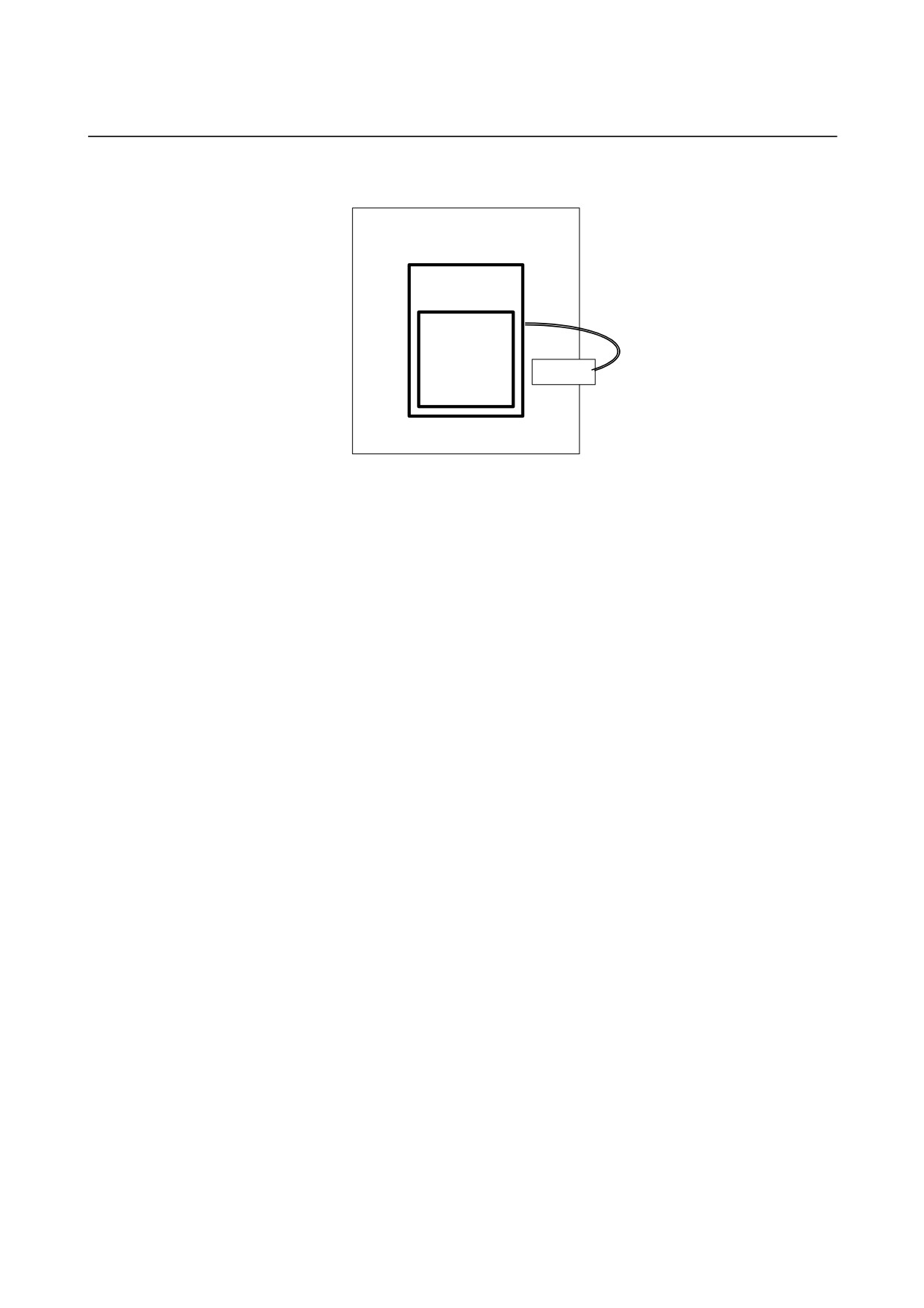
When a battery box is used)
Battery case
A06B-6050-K060
Battery
SVPM
A06B-6050-K061
+6V
CX5X (2)
0V
CX5X (1)
0.3 mm2 × 2
Screw terminal : M3
Housing : IL-L2S-S3L-B(N)
Crimp terminal : 1.25-4
Contact : IL-C2-1-00001
Manufacture :
Japan Aviation Electronics Industry
Example of cable
Terminal 1, White
CX5X
Crimp Terminal 1.25-4
6V
6V
Two 0.3mm2 Wires
0V
0V
Terminal 2, Black
Connector A06B-6093-K303
Crimp Terminal 1.25-4
• A connector (A06B-6093-K303) is optionally available.
Direction of insertion
+6V
Housing appearance
Cable side
0V
- 153 -
9.TOTAL CONNECTION DIAGRAM
SVPM
B-65322EN/02
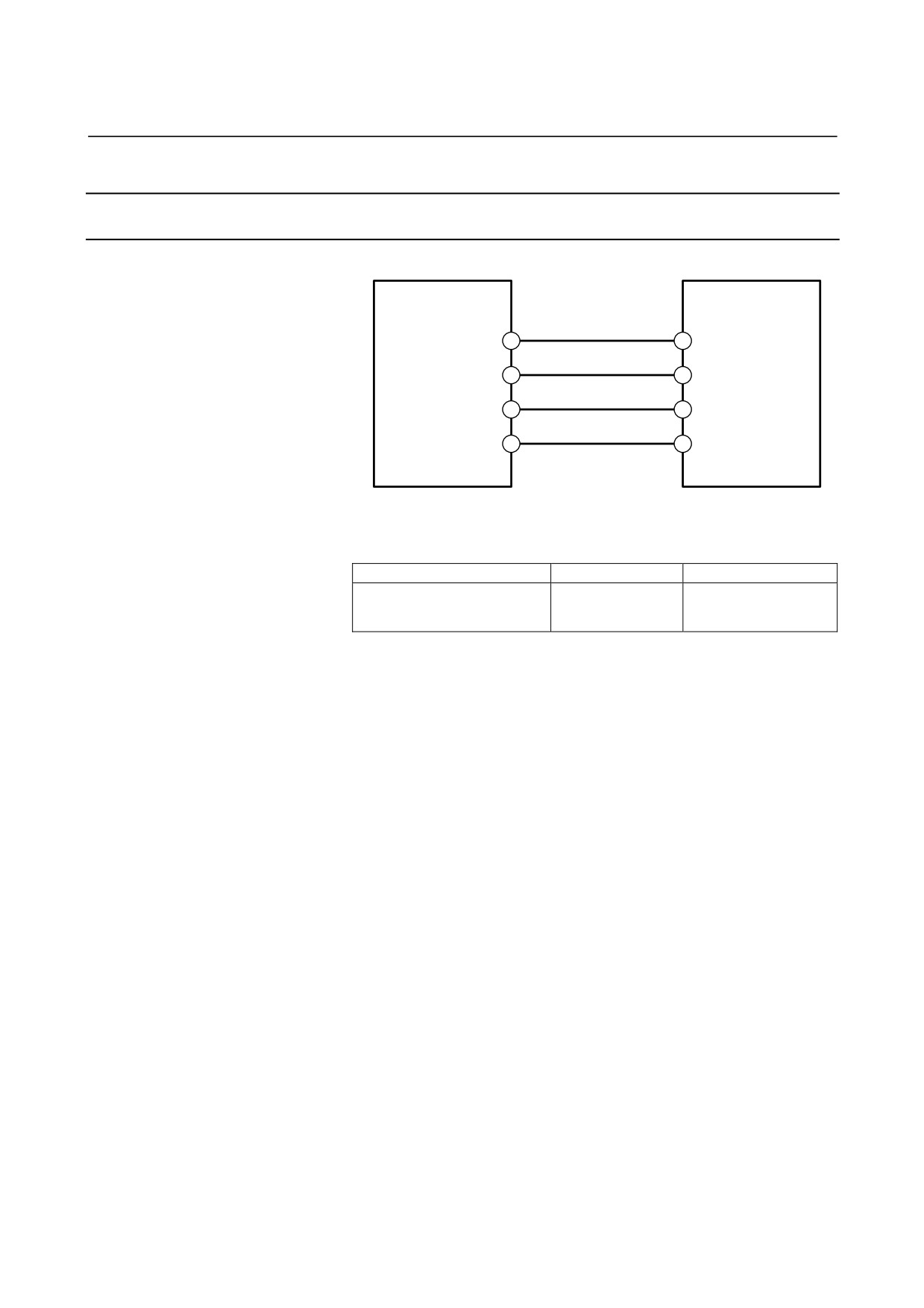
When the built-in battery is used)
SVPM
Battery case
A06B-6114-K501
Battery
A06B-6073-K001
CX5X
• Using the built-in battery (A06B-6073-K001) always requires the
battery case (A06B-6114-K501).
- 154 -
B-65322EN/02
SVPM
9.TOTAL CONNECTION DIAGRAM
9.3.2
Spindle Motor
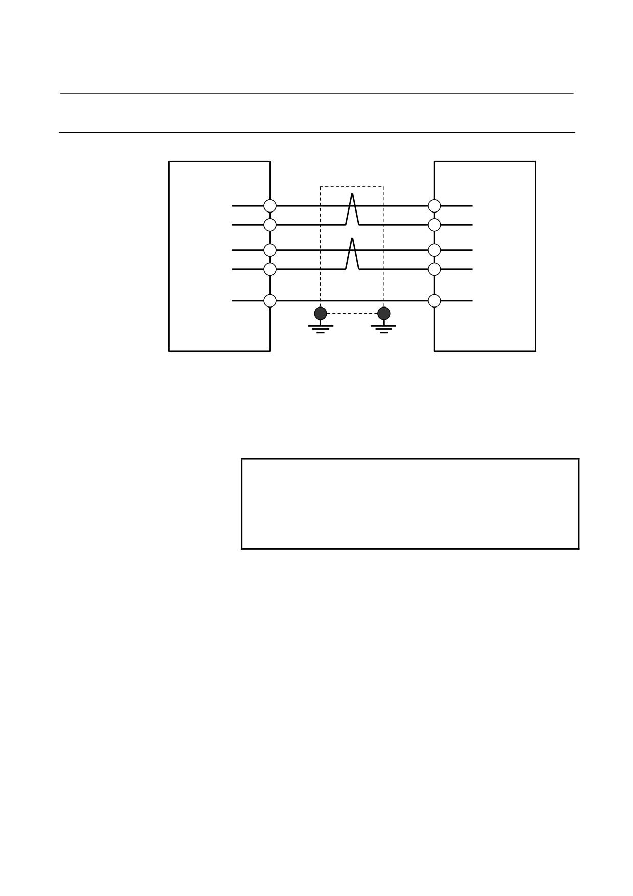
9.3.2.1 Details of cable K10
SVPM TB2
Spindle motor
(U)
(U)
(V)
(V)
(W)
(W)
(G)
(G)
To connect the cable to the SVPM, use a crimp terminal selected
according to the following table.
Amplifier model
Terminal screw
Tightening torque
SVPM2-5.5i to 15i
M5
2.0 to 2.5 N⋅m
SVPM3-5.5i to 15i
About the cable specification
Select the cable specification by considering the following conditions
for use.
<1> Motor current rating or current needed in use on a real machine
<2> Cable type (heat resistance temperature, etc.)
<3> Environment in which the cable is installed (operating ambient
temperature, etc.)
<4> Need of water proofing (pay attention to the diameter of the
applicable cable clamp)
<5> Certification for CE marking (compliance with various safety
standards and EMC standard)
<6> Securing insulation space among the cable pins at the time of
cabling
- 155 -
9.TOTAL CONNECTION DIAGRAM
SVPM
B-65322EN/02
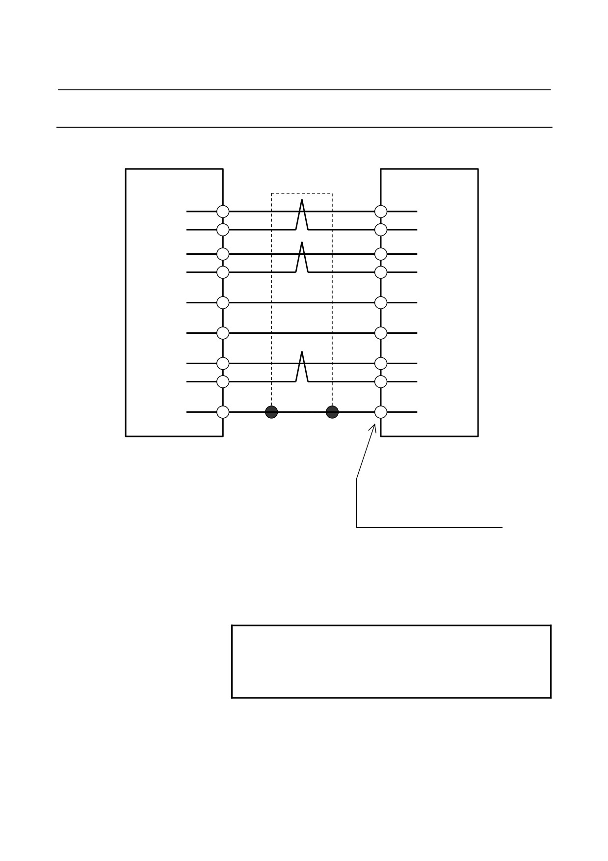
9.3.2.2 Details of cable K12
CNC
JA7A
JA7B
SVPM
(3)
SOUT
SIN1
(1)
(4)
*SOUT
*SIN1
(2)
(1)
SIN
SOUT1
(3)
(2)
*SIN
*SOUT1
(4)
(12),(14),(16)
0V
0V
(12),(14),(16)
Ground
Ground
plate
plate
20-pin half-pitch connector
20-pin half-pitch connector
(Note)
(Note)
Cable specification: 0.09 mm2 twisted pair with common shielded
Recommended cable (wire only): A66L-0001-0284#10P
See Section 5.4.1 for details of connectors applied to recommended
cable.
NOTE
If cable K12 is installed near the likes of a power
cable, its shielding wire must be connected to a
ground plate. If an SVPM is installed near the CNC,
however, it is not necessary to connect the shielding
wire to a ground plate.
- 156 -
B-65322EN/02
SVPM
9.TOTAL CONNECTION DIAGRAM
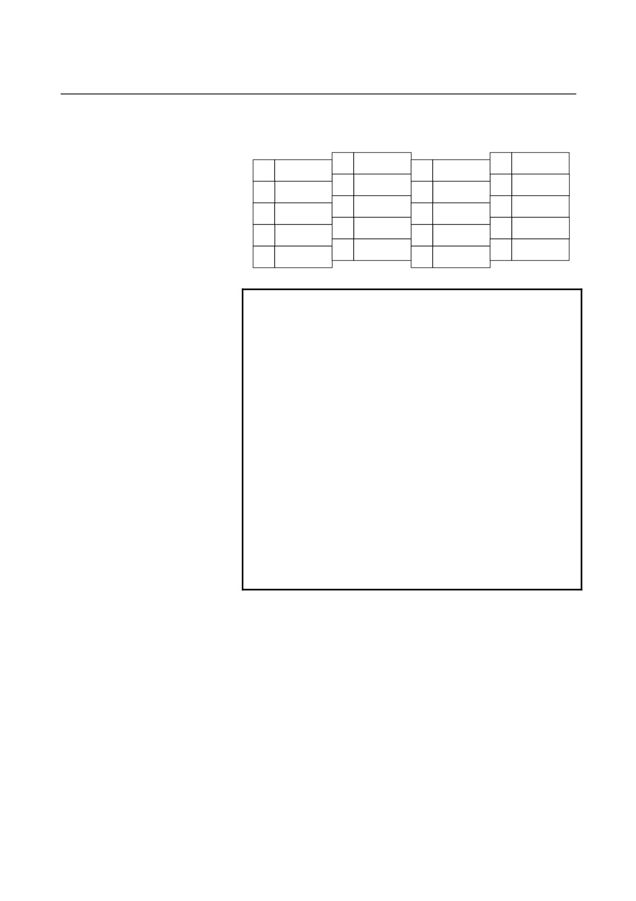
Connector pin assignment
JA7A and JA7B
10
20
5V (Note 1)
9
5V (Note 1)
19
8
18
5V (Note 1)
7
17
6
16
0V
5
15
4
*SOUT
14
0V
3
SOUT
13
2
*SIN
12
0V
1
SIN
11
NOTE
1 The +5V pin is intended for optical link transmission
based on the optical I/O link adapter. Do not use it
when a metal cable is being used; otherwise, the
+5V line of the CNC will be short-circuited with that
of the SVPM.
2 SVPM serial interface connection using an optical
fiber cable
The use of an optical I/O link adapter with the SVPM
serial interface extends the maximum allowable
length of the optical fiber cable to up to 200 m.
Use optical fiber cables in the following cases:
• When the required cable length is 20 m or longer.
• When the cable must be extended across multiple
cabinets, and the cabinets cannot be connected
with a grounding wire 5.5 mm2 or larger.
• The cable may be affected by noise, for example,
if the cable is laid near a strong magnetic noise
source like a welding machine or in parallel with a
power line over a long distance.
- 157 -
9.TOTAL CONNECTION DIAGRAM
SVPM
B-65322EN/02
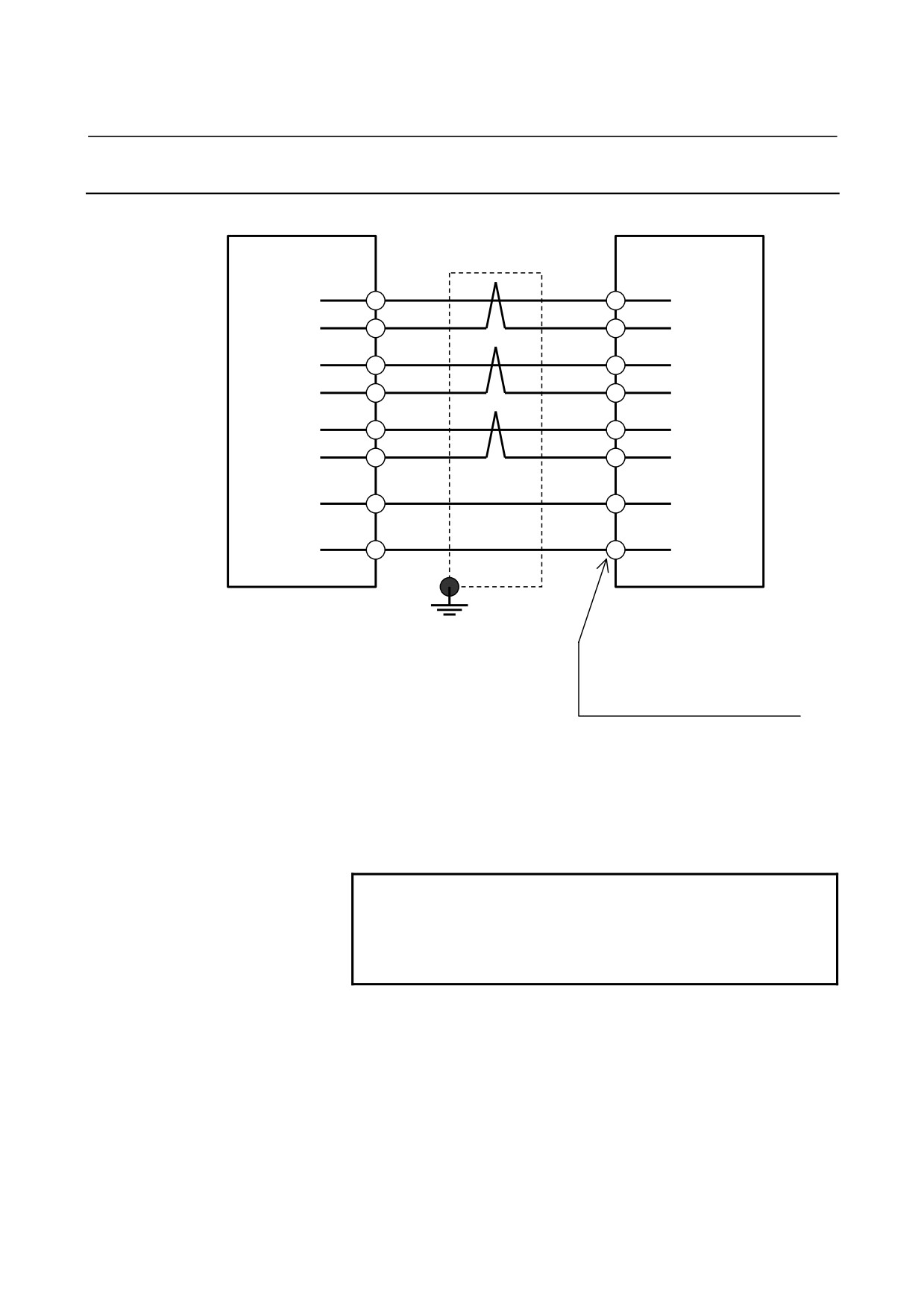
9.3.2.3 Details of cable K14
(1) For the motor with Mi sensor
SVPM JYA2
Mi sensor Motor
Shield
#A
(5)
MA
PA
(A2)
(6)
*MA
RA
(B2)
(7)
MB
PB
(A3)
(8)
*MB
RB
(B3)
(20)
5V
0.5mm2
5V
(A1)
(16)
0V
0.5mm2
0V
(B5)
(13)
THR1
THR1
(A6)
(15)
THR2
THR2
(B6)
(10)
SS
SS
(A5)
20-pin half-pitch connector
Manufactured by Tyco Electronics AMP
Housing : 178289-6
Contact : 1-175217-2
Cable specification :
6 common shielded cable
(Three 0.18mm2 twisted pairs + 0.5mm2 wires)
Recommended cable conductor : A66L-0001-0368
See Section 5.4.1 for explanations about the JYA2-side connector that
matches the recommended cable.
NOTE
If only one 5V line and only one 0V line are used,
use pins 20 and 16 for them, so that, if the
connector is attached the wrong way, the sensor
can be prevented from being damaged.
- 158 -
B-65322EN/02
SVPM
9.TOTAL CONNECTION DIAGRAM
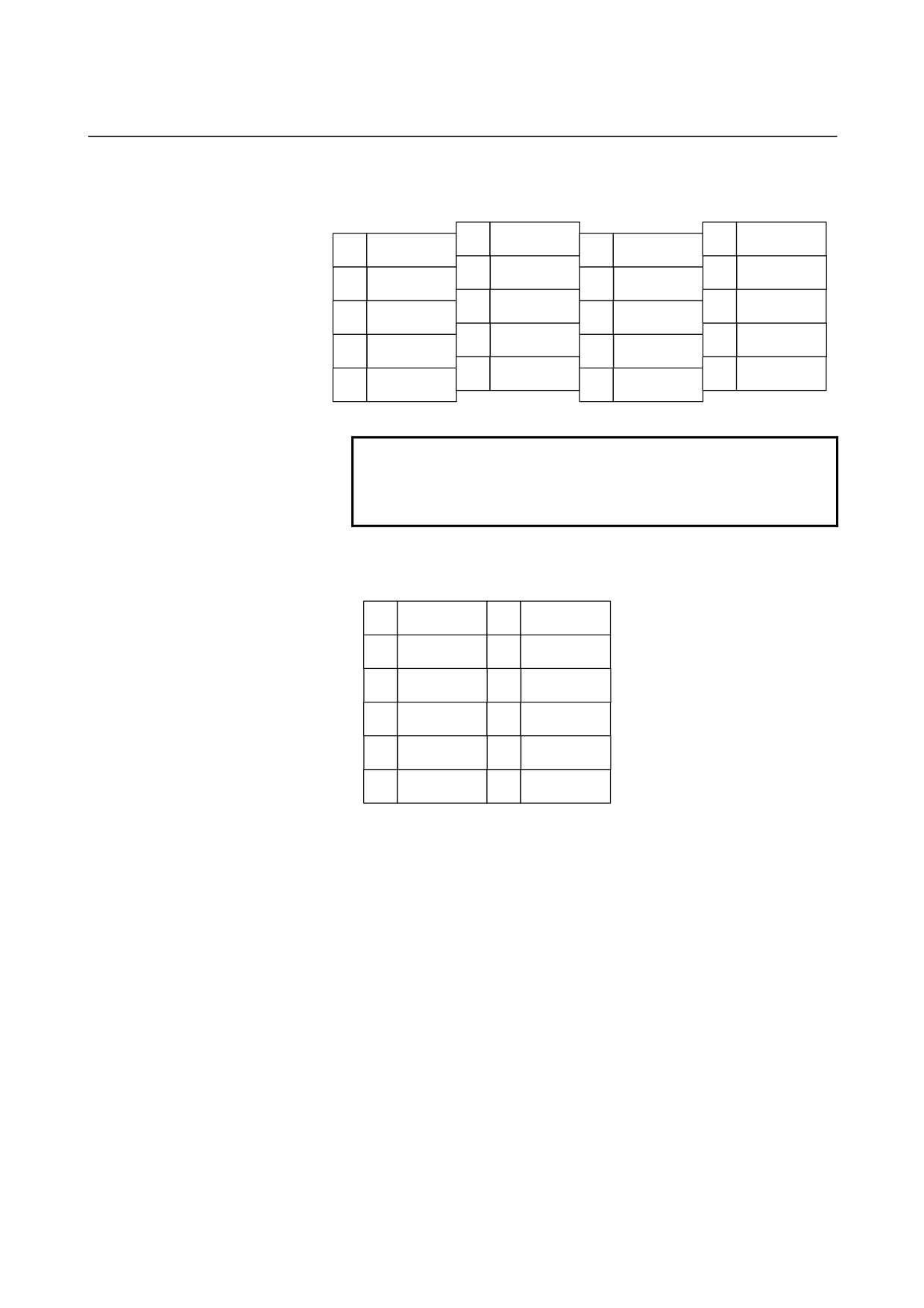
Connector pin assignment
JYA2
10
SS
20
5V
9
5V
19
#
8
*MB
18
5V
7
MB
17
#
6
*MA
16
0V
5
MA
15
THR2
4
#
14
0V
3
#
13
THR1
2
*MZ
12
0V
1
MZ
11
#
NOTE
Do not use any pin that is marked #, because they
may already be in use for input/output signals for
an optional PCB.
Pin arrangement of the connector (manufactured by Tyco Electronics
AMP) on the motor side
A1
+5V
B1
A2
PA
B2
RA
A3
PB
B3
RB
A4
B4
A5
SS
B5
0V
A6
THR1
B6
THR2
- 159 -
9.TOTAL CONNECTION DIAGRAM
SVPM
B-65322EN/02
9.3.2.4 Details of cable K16
SVPM JYA3
α position coder
Shield
(1)
PZ
PZ
(B)
(2)
*PZ
*PZ
(P)
(5)
PA
PA
(A)
(6)
*PA
*PA
(N)
(7)
PB
PB
(C)
(8)
*PB
*PB
(R)
(9),(18),(20)
5V
0.5mm2
5V
(H)
(12),(14),(16)
0V
0.5mm2
0V
(K)
20-pin half-pitch connector
Ground plate
Cannon connector
MS3106B20-29S
Cable specification : 6 common shielded cable
(Three 0.18mm2 twisted pairs + 0.5mm2 wires)
Recommended cable conductor : A66L-0001-0286
See Section 5.4.1 for explanations about the JYA3-side connector that
matches the recommended cable.
NOTE
If only one 5V line and only one 0V line are used,
use pins 20 and 16 for them, so that, if the
connector is attached the wrong way, the sensor
can be prevented from being damaged.
- 160 -
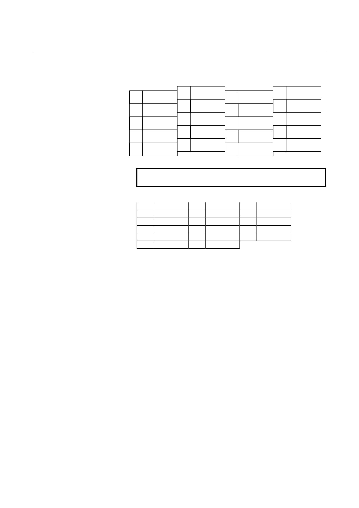
B-65322EN/02
SVPM
9.TOTAL CONNECTION DIAGRAM
Connector pin assignment
JYA3
10
#
20
5V
9
5V
19
#
8
*PB
18
5V
7
PB
17
#
6
*PA
16
0V
5
PA
15
EXTSC
4
#
14
0V
3
#
13
SCCOM
2
*PZ
12
0V
1
PZ
11
24V
NOTE
Do not use any pin that is marked #.
Pin arrangement of the cannon connector on the position coder side
A
PA
B
PZ
C
PB
D
E
F
G
H
+5V
J
K
0V
L
M
N
*PA
P
*PZ
R
*PB
S
T
- 161 -
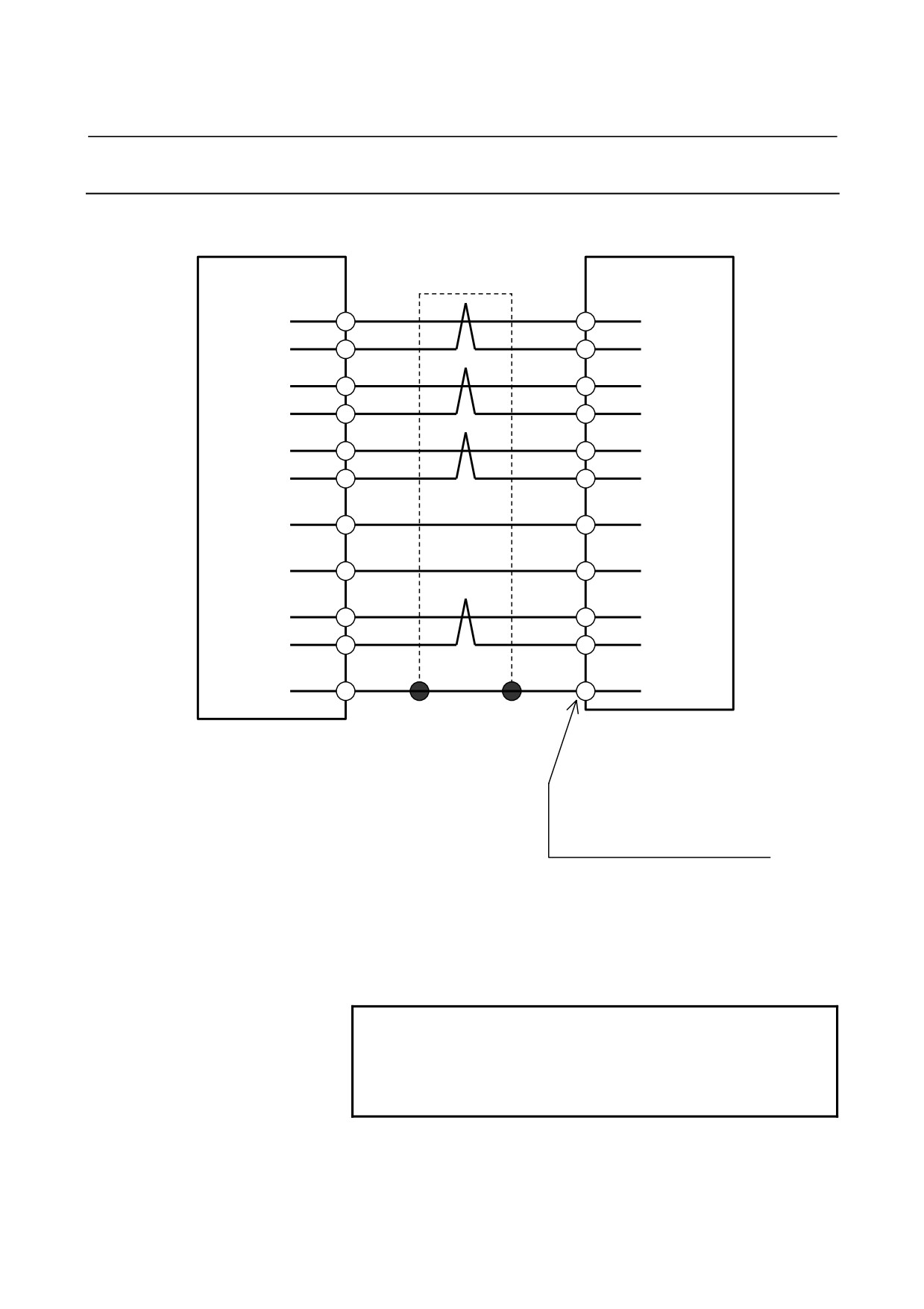
9.TOTAL CONNECTION DIAGRAM
SVPM
B-65322EN/02
9.3.2.5
Details of cable K17
(1) For the motor with MZi sensor
SVPM JYA2
MZi sensor Motor
Shield
#A
(1)
MZ
VZ
(A4)
(2)
*MZ
*VZ
(B4)
(5)
MA
VA
(A2)
(6)
*MA
*VA
(B2)
(7)
MB
VB
(A3)
(8)
*MB
*VB
(B3)
(9),(18),(20)
5V
0.5mm2
5V
(A1)
(12),(14),(16)
0V
0.5mm2
0V
(B5)
(13)
THR1
THR1
(A6)
(15)
THR2
THR2
(B6)
(10)
SS
SS
(A5)
20-pin half-pitch connector
Manufactured by tyco Electronics AMP
Housing : 178289-6
Contact : 1-175217-2
Cable specification : 6 common shielded cable
(Four 0.18mm2 twisted pairs + 0.5mm2 wires)
Recommended cable conductor : A66L-0001-0368
See Section 5.4.1 for explanations about the JYA2-side connector that
matches the recommended cable.
NOTE
If only one 5V line and only one 0V line are used,
use pins 20 and 16 for them, so that, if the
connector is attached the wrong way, the sensor
can be prevented from being damaged.
- 162 -
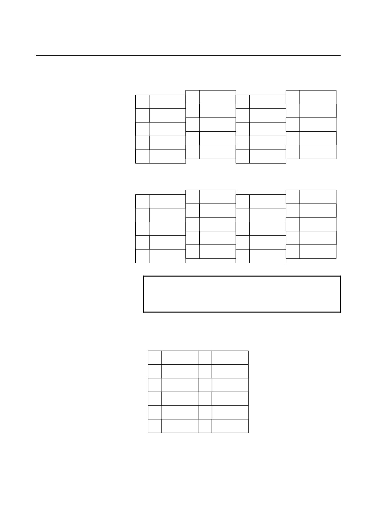
B-65322EN/02
SVPM
9.TOTAL CONNECTION DIAGRAM
Connector pin assignment
JYA2
10
SS
20
5V
9
5V
19
#
8
*MB
18
5V
7
MB
17
#
6
*MA
16
0V
5
MA
15
THR2
4
#
14
0V
3
#
13
THR1
2
*MZ
12
0V
1
MZ
11
#
JYA4
10
SS
20
5V
9
5V
19
#
8
*MB
18
5V
7
MB
17
#
6
*MA
16
0V
5
MA
15
4
#
14
0V
3
#
13
2
*MZ
12
0V
1
MZ
11
#
NOTE
Do not use any pin that is marked #, because they
may already be in use for input/output signals for
an optional PCB.
Pin arrangement of the connector (manufactured by Tyco Electronics
AMP) on the motor side
A1
+5V
B1
A2
VA
B2
*VA
A3
VB
B3
*VB
A4
VZ
B4
*VZ
A5
SS
B5
0V
A6
THR1
B6
THR2
- 163 -
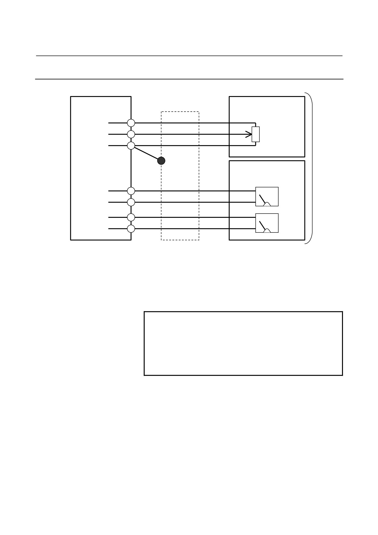
9.TOTAL CONNECTION DIAGRAM
SVPM
B-65322EN/02
9.3.2.6 Details of cable K33
SVPM JY1
Analog override
Shield
(1)
OVR1
Variable
(2)
OVR2
resistor
(20)
0V
(*)
Speedometer
Load meter
(16)
LM (Note)
(18)
0M
(17)
SM
(19)
0M
20-pin half-pitch connector
Power magnetics cabinet
Cable specification : 0.09mm2 common shielded cable
Recommended cable conductor : A66L-0001-0284#10P
See Section 5.4.1 for explanations about the JY1-side connector that
matches the recommended cable.
NOTE
1 Select such an external resistance such that
VR+R1 falls within the range between 2 kΩ and 10
kΩ .
2 No LM output is included in the #C specification.
For the SM output, select the load meter or
speedometer by parameter setting.
- 164 -
B-65322EN/02
SVPM
9.TOTAL CONNECTION DIAGRAM
Connector pin assignment
JY1
10
#
20
0V
9
#
19
0M
8
#
18
0M
7
#
17
SM
6
#
16
LM
5
#
15
#
4
#
14
#
3
#
13
#
2
OVR2
12
#
1
OVR1
11
#
NOTE
Pins indicated # are intended to input or output
signals used on a spindle check board. Do not
connect any other signal line to them.
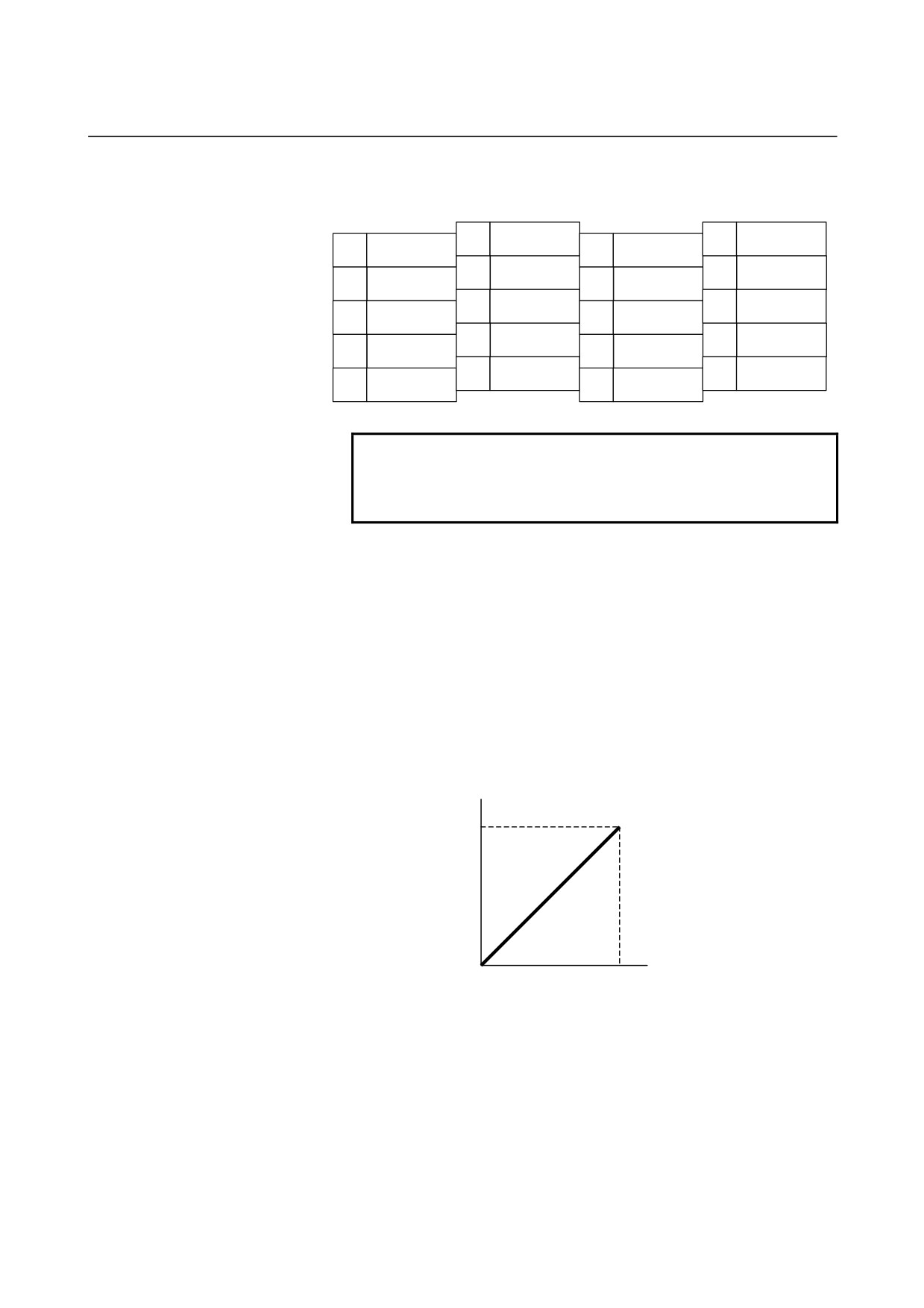
Voltage signal for the speedometer (SM)
By externally connecting a tachometer, the speed of the spindle motor
can be indicated. The voltage (DC) proportional to the speed (for the
#C specification, an estimated speed) is output, regardless of the
rotation direction of the motor. At the maximum motor speed, +10 V
is output.
The output voltage of the speedometer in the forward direction and
reverse direction is calibrated using a parameter. The precision is ±3%
Max.
+10V
Output voltage
0V
0
Maximum speed
Motor speed min-1
- 165 -
9.TOTAL CONNECTION DIAGRAM
SVPM
B-65322EN/02
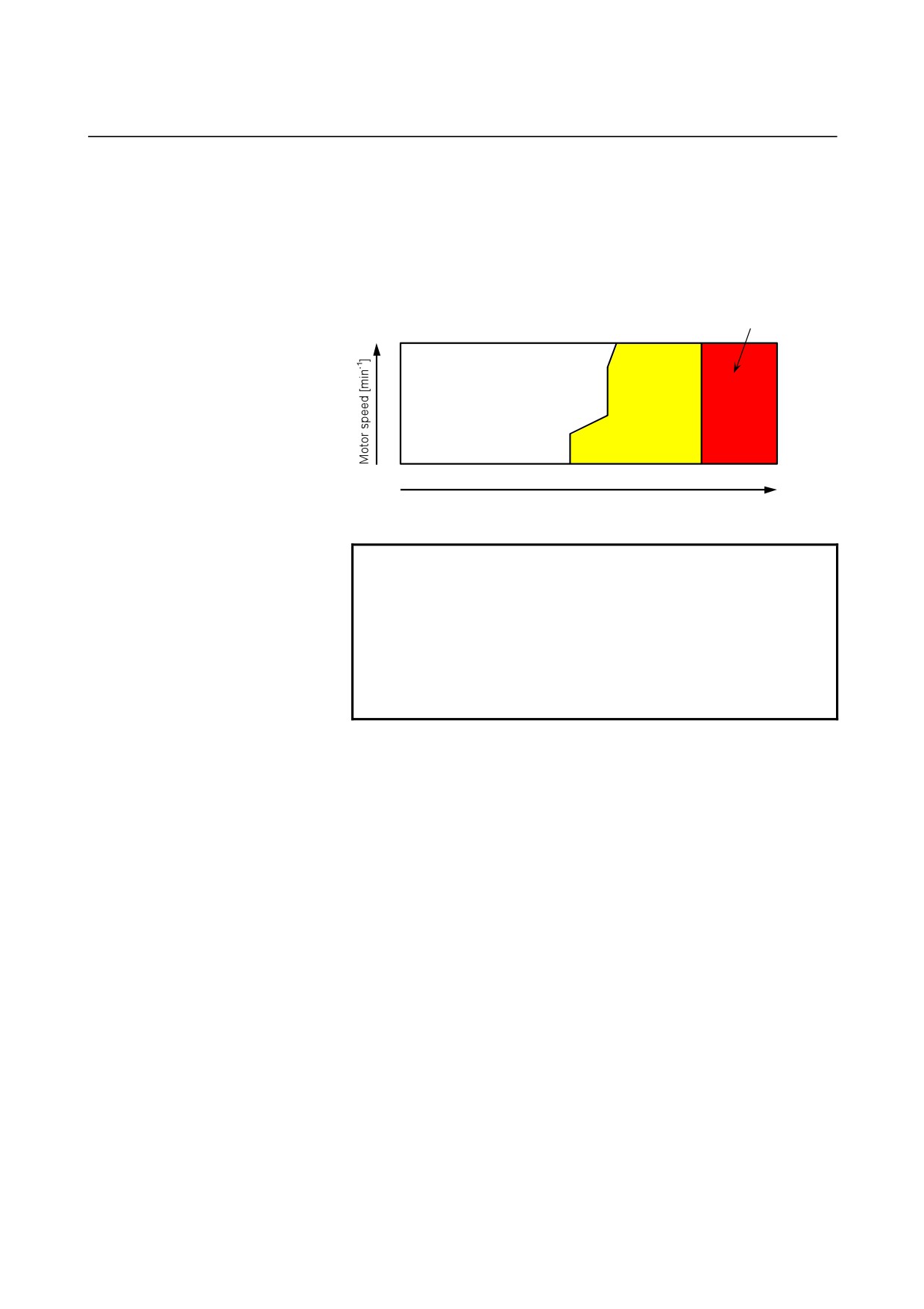
Voltage signal for the load meter (LM)
The load meter indicates the percentage of the load to the maximum
motor output
(load ratio). A voltage of
10 V is output at the
maximum output.
• Legend
㪩㪼㪻
㪩㪸㫋㪼㪻㩷㫆㫌㫋㫇㫌㫋㩷㪼㫏㪺㪼㪼㪻㪼㪻
㪮㪿㫀㫋㪼
㪰㪼㫃㫃㫆㫎
Continuous rating
short-time
rating
㪇
㪇
㪈㪇
Load meter [V]
(Max. 10V)
NOTE
1 The vertical axis represents the motor speed. If
the spindle-to-motor speed ratio is not 1:1, it is
recommended to convert the motor speed to the
spindle speed.
2 The precision of load meter voltage depends on the
used speed and input voltage. The maximum error
is about ±15%.
- 166 -