FANUC AC Servo Amplifiers βi Series. Description Manual (B-65322EN/02) - page 5
B-65322EN/02
SVPM
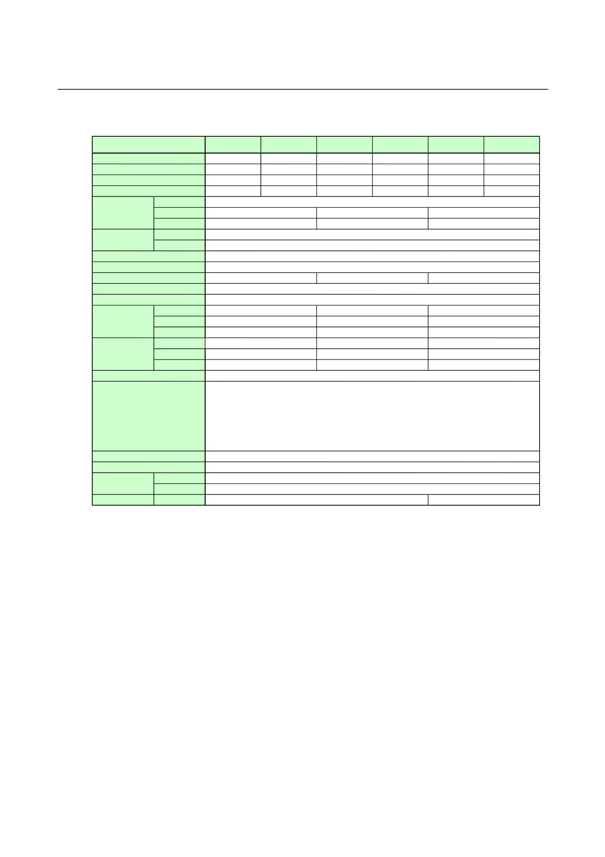
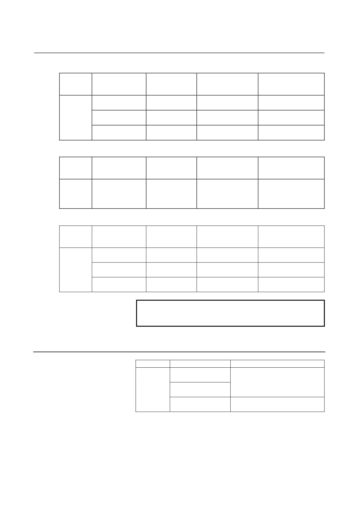
3.SPECIFICATIONS
Three-axis type (SVPM3)
SVPM3-5.5i
SVPM3-5.5i
SVPM3-11i
SVPM3-11i
SVPM3-15i
SVPM3-15i
Item
(TypeA)
(TypeC)
(TypeA)
(TypeC)
(TypeA)
(TypeC)
Unit specification
A06B-6134-H301#A A06B-6134-H301#CA06B-6134-H302#A A06B-6134-H302#CA06B-6134-H303#A A06B-6134-H303#C
Power PC board
A20B-2101-0023
A20B-2101-0023
A20B-2101-0024
A20B-2101-0024
A20B-2101-0025
A20B-2101-0025
Control PC board
A20B-2101-0013
A20B-2101-0013
A20B-2101-0013
A20B-2101-0013
A20B-2101-0013
A20B-2101-0013
Module PC board
A20B-2902-0670
A20B-2902-0672
A20B-2902-0670
A20B-2902-0672
A20B-2902-0670
A20B-2902-0672
Input voltage
200-240VAC (+10%,-15%) 50/60Hz
Main power supply
Input current(50Hz)
26Arms
49Arms
64Arms
3-phase input
Power supply rating
9KVA
17KVA
22KVA
Control power supply
Input voltage
24VDC ± 10%
Input current
1.5Amax.
Servo HRV control
HRV2, HRV3
Control method
Sine wave PWM control with Transistor Bridge
Rated output current of spindle
29Arms
56Arms
64Arms
Basic output frequency of spindle
60Hz
Output frequency range of spindle
1Hz-1KHz
Rated output current
L axis
6.5Arms
6.5Arms
13Arms
of servo axis
M axis
6.5Arms
6.5Arms
13Arms
N axis
13Arms
13Arms
13Arms
Maximum output
L axis
20Ap
20Ap
40Ap
current of servo axis
M axis
20Ap
20Ap
40Ap
N axis
40Ap
40Ap
40Ap
Output frequency range of servo axis
0Hz-334Hz
High Current
IPM Abnormal
High Voltage of DC Link
Protection function
Low Voltage of DC Link
Low Voltage of Control Power Supply
Short Time Overload
FSSB Communication Error
Ambient temperature
0-+55 °C
Weight
14.8kg
Dimensions
Outside dimensions
260x380x272
Fin dimensions
260x380x100
Option
AC reactor
A81L-0001-0155
A81L-0001-0156
- 105 -
3.SPECIFICATIONS
SVPM
B-65322EN/02
3.2
COOLING FAN MOTOR
Install a cooling fan motor listed below.
Otherwise, make arrangements so that the required air flow can be
obtained.
Ordering number
Optional fan
Required air flow
SVPM2-5.5i
SVPM3-5.5i
A06B-6134-K001
A06B-6134-H201#*
A06B-6134-H301#*
One unit
SVPM2-11i
SVPM3-11i
A06B-6134-K001
2 m/s
A06B-6134-H202#*
A06B-6134-H302#*
One unit
SVPM2-15i
SVPM3-15i
A06B-6134-K001
A06B-6134-H203#*
A06B-6134-H303#*
One unit
3.3
HOW TO OBTAIN A POWER SUPPLY CAPACITY
- Output capacity -
The output capacity is the sum of the total spindle motor
continuous output rating multiplied by a coefficient (1.15) and
the servo motor continous output rating multiplied by a
coefficient (0.6).
-Power supply capacity-
SVPM*-5.5i
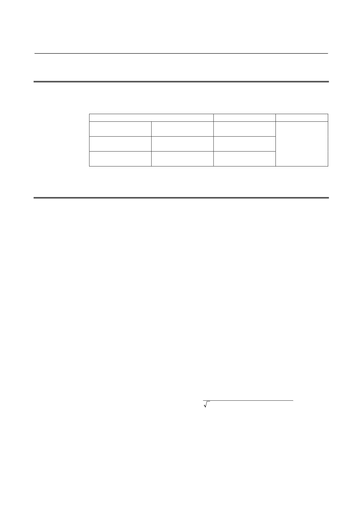
Power supply capacity (kVA) = output capacity (kW) × 1.64
SVPM*-11i
Power supply capacity (kVA) = output capacity (kW) × 1.55
SVPM*-15i
Power supply capacity (kVA) = output capacity (kW) × 1.47
[How to obtain the input current so units to be installed at the
input section can be selected]
Obtain the SVPM input current, using the following expression.
Use it as a reference value in selecting a circuit breaker, magnetic
contactor, and power cable.
(Margin for selection:
1 to 1.5 times)
Power supply capacity
(kVA)
SVPM
input current
(Arms)
=
×1.2 (margin)
3
×
nominalpower supply voltage
(Vrms)
(Assume the nominal power supply voltage (Vrms) is usually
200 Vrms.)
- 106 -
B-65322EN/02
SVPM
3.SPECIFICATIONS
3.4
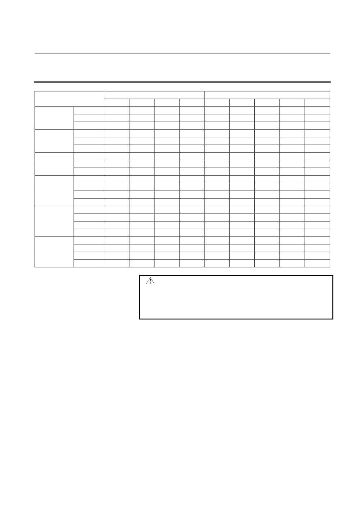
APPLICABLE MOTORS
Spindle Motor
Servo Motor
β3/10000i
β6/10000i
β8/8000i
β12/7000i
β2/4000is
β4/4000is
β8/3000is
β12/3000is
β22/2000is
Spindle
O
SVPM2-5.5i
Servo L axis
O
O
O
A06B-6134-H201*
Servo M axis
O
O
O
Spindle
**
O
O
SVPM2-11i
Servo L axis
O
O
O
A06B-6134-H202*
Servo M axis
O
O
O
Spindle
**
**
**
O
SVPM2-15i
Servo L axis
**
**
**
O
O
A06B-6134-H203*
Servo M axis
**
**
**
O
O
Spindle
O
SVPM3-5.5i
Servo L axis
O
O
O
A06B-6134-H301*
Servo M axis
O
O
O
Servo N axis
**
**
**
O
O
Spindle
**
O
O
SVPM3-11i
Servo L axis
O
O
O
A06B-6134-H302*
Servo M axis
O
O
O
Servo N axis
**
**
**
O
O
Spindle
**
**
**
O
SVPM3-15i
Servo L axis
**
**
**
O
O
A06B-6134-H303*
Servo M axis
**
**
**
O
O
Servo N axis
**
**
**
O
O
CAUTION
** Combining with this motor requires changing the
motor control parameter.
An incorrect parameter setting may damage the
motor.
- 107 -
3.SPECIFICATIONS
SVPM
B-65322EN/02
3.5
CIRCUIT BREAKER, MAGNETIC CONTACTOR, AND AC
REACTOR
3.5.1
AC Line Filter and Magnetic Contactor
The ratings of the circuit breakers and magnetic contactor are
determined by the specifications of the power supply module used.
The ordering specification drawing numbers and specifications of
circuit breakers and magnetic contactors are listed below.
When the user prepares circuit breakers and a magnetic contactor, use
those that satisfy the specifications listed below.
-
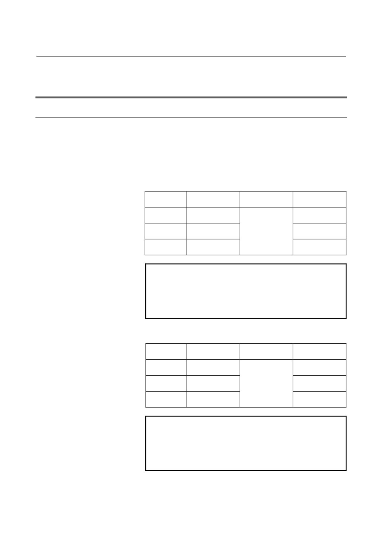
Specifications of circuit breakers and magnetic contactors
SVPM name
Circuit breaker 1
Circuit breaker 2
Magnetic
contactor
SVPM*-5.5i
30A
30A
(*:
2 or 3)
SVPM*-11i
55A
5A
55A
(*:
2 or 3)
SVPM*-15i
70A
70A
(*:
2 or 3)
NOTE
1 For the locations of the circuit breakers and
magnetic contactor, see Section 1.2,
"CONFIGURATION".
2 Select the rated voltages of the circuit breakers
according to the power supply voltage.
-
Recommended products
Manufactured by Fuji Electric Co., Ltd.
SVPM name
Circuit breaker 1
Circuit breaker 2
Magnetic
contactor
SVPM*-5.5i
EA103B/50
SC- N 1
(*:
2 or 3)
SVPM*-11i
EA103B/60
EA33/5
SC- N 2
(*:
2 or 3)
SVPM*-15i
EA103B/75
SC- N2S
(*:
2 or 3)
NOTE
For details, refer to the brochure supplied by Fuji
Electric Co., Ltd.
Note that the coil voltage specification of the
magnetic contactor varies depending on the power
supply voltage and frequency used.
- 108 -
B-65322EN/02
SVPM
3.SPECIFICATIONS
- Ordering specification drawing number of circuit breaker 1
Ordering
Circuit breaker
Circuit breaker cover
Type
Applicable model
specification
specification
specification
drawing No.
SVPM*-5.5i
A06B-6077-K102
Fuji Electric, EA103B/50
Fuji Electric, BZ-TB20B-3
(*:
2 or 3)
SVPM*-11i
Option
A06B-6077-K103
Fuji Electric, EA103B/60
Fuji Electric, BZ-TB20B-3
(*:
2 or 3)
SVPM*-15i
A06B-6077-K104
Fuji Electric, EA103B/75
Fuji Electric, BZ-TB20B-3
(*:
2 or 3)
- Ordering specification drawing number of circuit breaker 2
Ordering
Circuit breaker
Circuit breaker cover
Type
Applicable model
specification
specification
specification
drawing No.
For control power
supply
Fuji Electric,
Option
A06B-6077-K106
Fuji Electric, EA33/5
(common to all SVPM
BZ-TB10B-503
models)
- Ordering specification drawing number of magnetic contactor
Ordering
Magnetic contactor
Magnetic contactor
Type
Applicable model
specification
specification
cover specification
drawing No.
SVPM*-5.5i
A06B-6077-K122
Fuji Electric, SC-1N
Fuji Electric, SZ-1N/T
(*:
2 or 3)
SVPM*-11i
Option
A06B-6077-K123
Fuji Electric, SC-2N
Fuji Electric, SZ-1N/T
(*:
2 or 3)
SVPM*-15i
A06B-6077-K124
Fuji Electric, SC-2SN
Fuji Electric, SZ-2SN/T
(*:
2 or 3)
NOTE
The coil voltage specification of the magnetic
contactor is 200 VAC.
3.5.2
AC Reactor
Type
Applicable model
Ordering specification drawing No.
SVPM*-5.5i
(*:
2 or 3)
A81L-0001-0155
SVPM*-11i
Basic
(*:
2 or 3)
SVPM*-15i
A81L-0001-0156
(*:
2 or 3)
- 109 -
3.SPECIFICATIONS
SVPM
B-65322EN/02
3.6
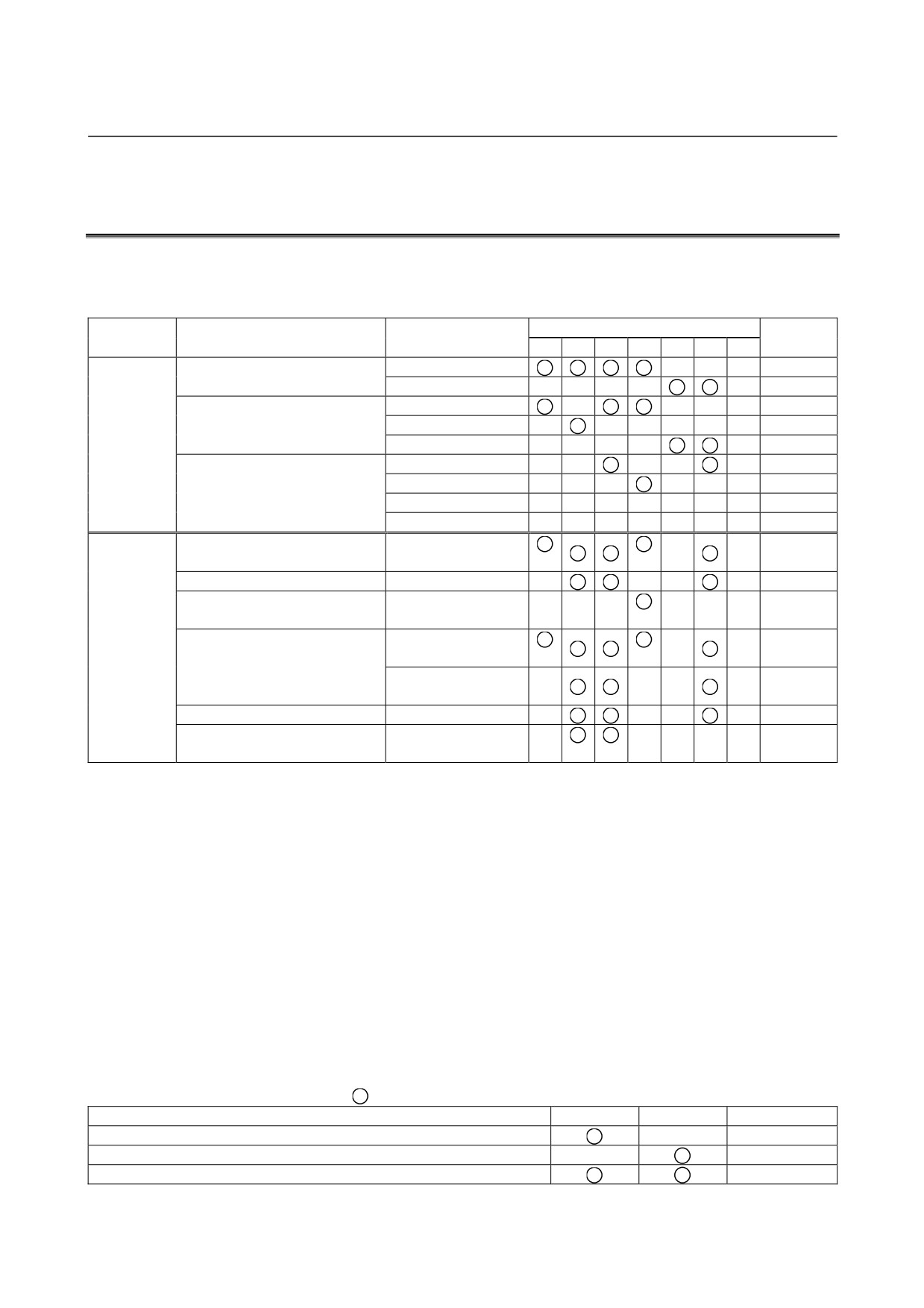
SPINDLE AXIS TYPES (#A AND #C) AND APPLICABLE
SENSORS
Two models (#A and #C) are available for each sensor for spindles.
The following table lists combinations of applicable sensors and
functions.
Configuration
Remarks
1
2
3
4
5
6
Ordering number
#A (TYPE A)
A06B-6134-H***#A, #C
#C (TYPE C)
Mi sensor
Spindle
Sensor on the motor
MZi sensor
system
Without sensor
configuration
α position coder
*3
External one-rotation
*3
Sensor on the spindle
Rigid tapping
*1
*2
Orientation by a position coder
Orientation by the external
*5
one-rotation signal
*2
Velocity
Function
*4
synchronization
*2
*2
Spindle synchronization
Phase
*4
synchronization
Threading
Cs contouring control
*6
*7
*1
The spindle and motor must be interconnected with a timing belt
or gear. No orientation is available to adjust the tapping start
position.
*2
The spindle and motor must be interconnected with a timing belt
or gear.
*3
The spindle and sensor must be interconnected in one-to-one
connection mode.
*4
Two motor amplifiers are required.
*5
Note that the stop position moves by a backlash between the
spindle and motor because of the theory of operation.
*6
This function is enabled on the machine that the spindle motor is
directly connected to a spindle.
*7
The resolution of position detection is 4096 p/rev.
Other spindle axis functions
: Applicable
#A
#C
Remarks
Analog output of load meter and speedometer
Connector JY1
Analog output of either load meter or speedometer
Connector JY1
Analog override input
Connector JY1
- 110 -
B-65322EN/02
SVPM
3.SPECIFICATIONS
3.7
DERATING
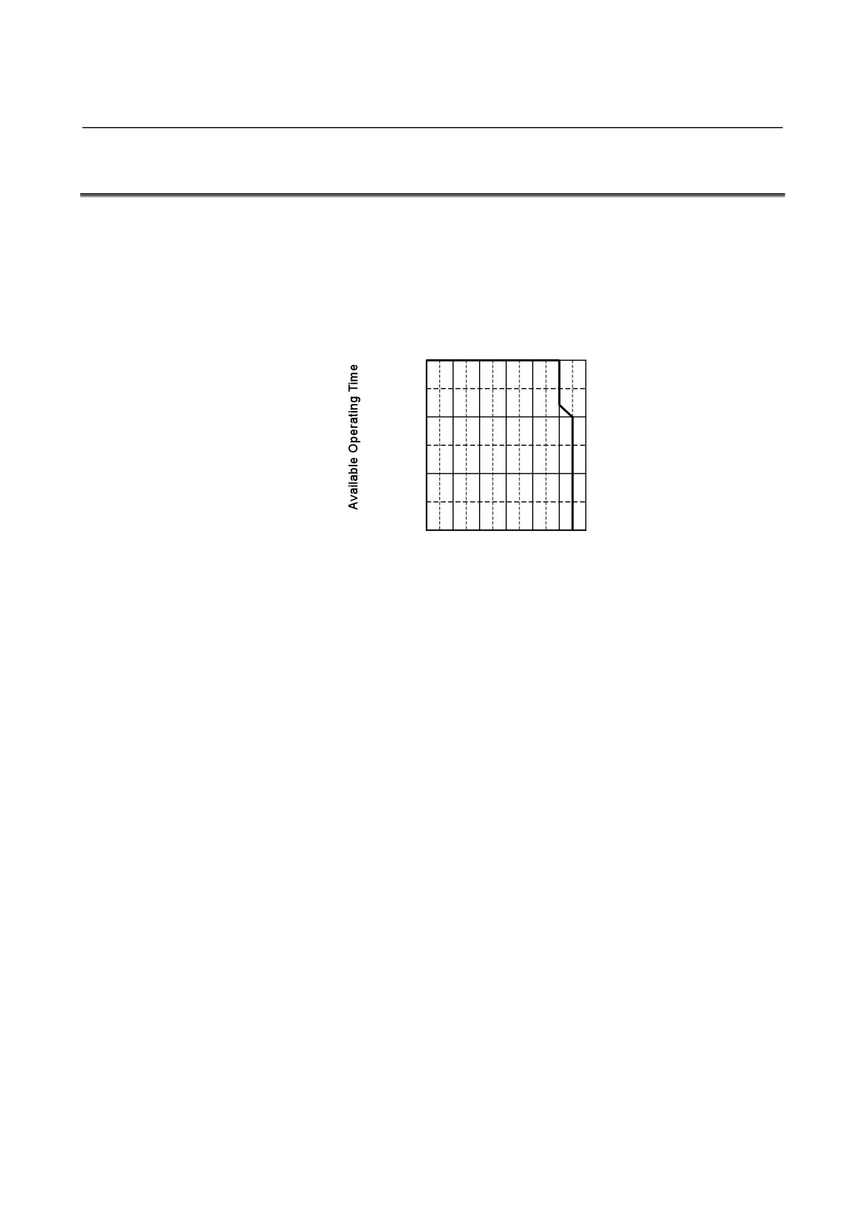
Derating
Consider derating as shown below, according to ambient
temperatures.
Target models: All SVPM models
15
min.
10
min.
5
min.
0
0
10
20
30
40
50
60 °C
Ambient temperature
- 111 -
4.ORDERING INFORMATION
SVPM
B-65322EN/02
4
ORDERING INFORMATION
Refer to the order list (B-65321EN).
- 112 -
B-65322EN/02
SVPM
5.POWER SUPPLY
5
POWER SUPPLY
- 113 -
5.POWER SUPPLY
SVPM
B-65322EN/02
5.1
INPUT POWER SUPPLY
5.1.1
Three-phase Input Power Supply for Motor Power
-
Nominal rated voltage: 200 to 240 VAC
-
Allowable voltage fluctuation: -15% to +10%
-
Frequency: 50/60 Hz
-
Allowable frequency fluctuation: ±2 Hz
-
Power supply impedance: Voltage fluctuation cased by load (at
maximum output) not to exceed 7%
-
Power supply unbalance: Within ±5% of the rated voltage
NOTE
The allowable voltage fluctuation is a change
observed for several minutes. It is not a continuous
change.
(1)
If the power supply impedance is high, and the voltage
fluctuation exceeds the specification, an SVPM alarm (DC link
low voltage alarm or DC link overvoltage alarm) or a motor
output drop may result.
Use an appropriate power supply of which input voltage
fluctuation during motor acceleration does not exceed 7%.
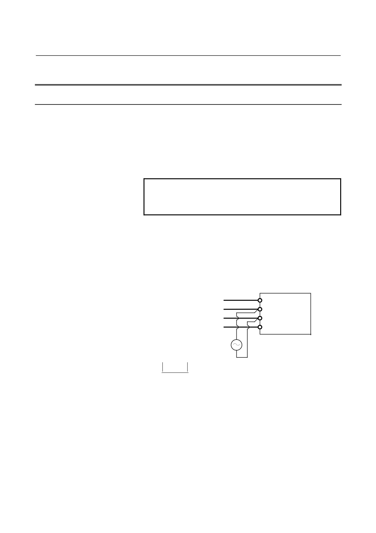
[Checking the power supply impedance]
R
AC power
S
supply
SVPM
T
G
AC
voltmeter
E0−
E1
×100(%)
<
7(%)
E0
E0: Voltage under no load
E1: Voltage at maximum output
(power running and
regeneration)
(2)
Input the power supply to the SVPM control circuit (power
supply input of CXA2C) before turning on the CNC or within
500 ms after turning on the CNC.
(3)
Because a capacitor for power-factor improvement may affect
power supply regeneration, it is recommended that such a
capacitor be not installed.
(4)
The rated output of the motor is guaranteed on the rated input
voltage. When the input voltage changes, the rated output may
not be observed even if the change is within the allowable
fluctuation range.
- 114 -
B-65322EN/02
SVPM
5.POWER SUPPLY
5.1.2
Single-phase Input for Control Power
Be sure to use a stabilized power supply as the 24-V power supply for
amplifiers. The
24-V power supply for motor brakes cannot be
shared.
-
Nominal rated voltage: 24VDC
-
Allowable voltage fluctuation:
±10%(including momentary variations)
-
Power supply ratings: 1.5A (per amplifier)
For the specification and circuit configuration of the external 24-VDC
power supply, see "POWER SUPPLY" in Part I, "SVM".
- 115 -
5.POWER SUPPLY
SVPM
B-65322EN/02
5.2
POWER TRANSFORMER FOR EXPORTS
When a SVPM of the 200V input series is used in an area where the
input voltage is not within the range of 200 to 230VAC, a power
transformer is required.
The ordering drawing numbers and
specifications of power transformers manufactured by FANUC are
listed below. When other than a FANUC power transformers is to be
prepared by the user, it must satisfy the transformer specifications
indicated Section 2.1.
Ordering drawing numbers of power transformers manufactured by
FANUC
Ordering number
Name
Remarks
For SVPM*-5.5i
A06B-6052-J001
(*:2 or 3)
Primary
For SVPM*-11i
380/415/460VAC
A06B-6044-J006
(*:2 or 3)
Secondary
For SVPM*-15i
200VAC
A06B-6044-J007
(*:2 or 3)
- 116 -
B-65322EN/02
SVPM
5.POWER SUPPLY
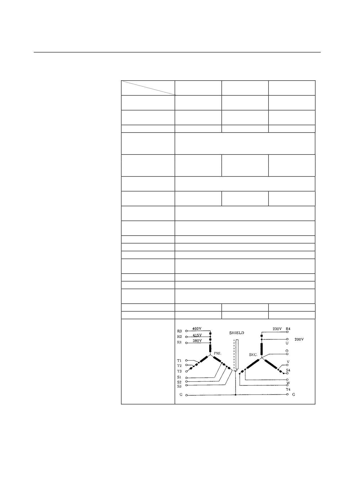
- Specifications of power transformers manufactured by FANUC
Power transformer for SVPM
Model
SVPM*-5.5i
SVPM*-11i
SVPM*-15i
Item
Ordering drawing
A06B-6052-J001
A06B-6044-J006
A06B-6044-J007
number
FANUC drawing
A80L-0001-0496
A80L-0001-0313
A80L-0001-0314
number
Rated capacity
10kVA
20kVA
30kVA
380/415/460VAC
Rated primary
230VAC (The secondary is used as an autotransformer.)
voltage
+10% -15%, 50/60±1Hz, 3φ
15A (at 380V)
30A (at 380V)
46A (at 380V)
Rated primary current
14A (at 415V)
28A (at 415V)
42A (at 415V)
13A (at 460V)
25A (at 460V)
38A (at 460V)
Rated secondary
AC200/220/230V
voltage
Rated secondary
29A
58A
87A
current
Voltage regulation at
5%
the secondary
Voltage deviation at
±3%
the secondary
Connection
Y-Y connection
Insulation
Class H (maximum allowable temperature : 180°C)
Ambient temperature
0 to 45°C
Allowable
135deg
temperature rise
Relative humidity
Max. 95%RH
Type
Dry type, natural air cooling type
Dielectric withstand
2000VAC, for 1 minute
voltage
Weight
Max. 61kg
Max. 115kg
Max. 165kg
Outline drawing
Fig. 8.1.4(a)
Fig. 8.1.4(b)
Fig. 8.1.4(c)
(Neutral point)
Connection diagram
(Primary)
(Secondary)
- 117 -
5.POWER SUPPLY
SVPM
B-65322EN/02
- Connecting a power transformer
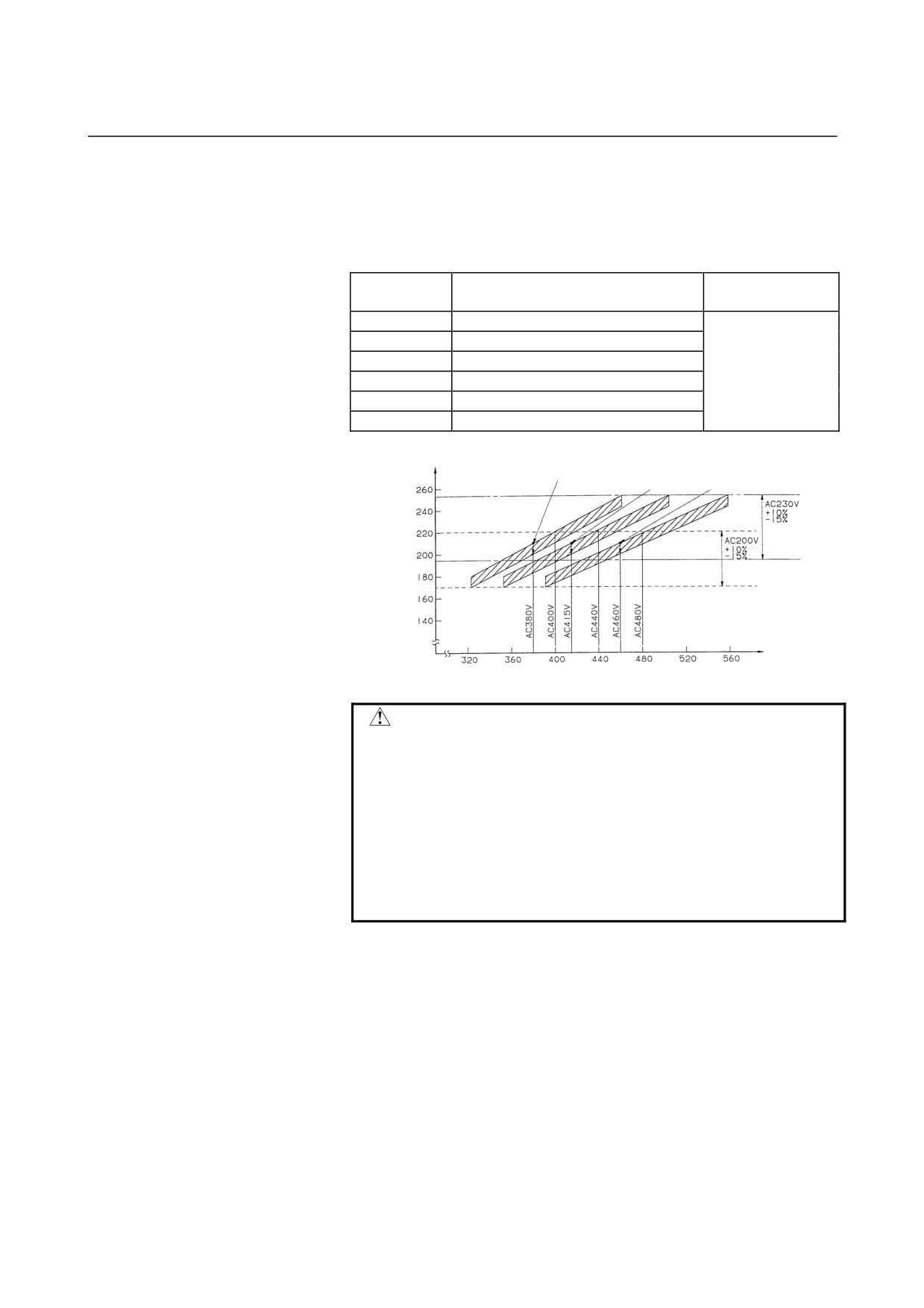
Power transformers must be set according to the supply voltage used.
(a) Connection points of power transformers for SVPM*-5.5i,
SVPM*-11i, and SVPM*-15i
Supply
Connection points at the primary
Remarks
voltage
380VAC
R - R1, S - S1, T - T1(380-V tap))
400VAC
R - R1, S - S1, T - T1(380-V tap)
415VAC
R - R2, S - S2, T - T2(415-V tap)
440VAC
R - R2, S - S2, T - T2(415-V tap)
460VAC
R - R3, S - S3, T - T3(460-V tap)
480VAC
R - R3, S - S3, T - T3(460-V tap)
Voltage regulation (approximately 10V) when the load
varies (0% to 100%) with the 380-VAC tap set
With the 415-VAC tap set With the 460-VAC tap set
Secondary
output
voltage (V)
AC input voltage (V)
CAUTION
1 When installing a transformer in a cabinet, be
careful to ensure that the transformer does not
thermally affect other equipment. For example,
separate the transformer from the other equipment.
2 When installing a transformer outside the cabinet,
make sure that the transformer is not directly
exposed to cutting chips or coolant.
3 If there is a possibility of the transformer falling,
secure the transformer with bolts or similar.
- 118 -
B-65322EN/02
SVPM
6.INSTALLATION CONDITIONS AND NOTES
6
INSTALLATION CONDITIONS AND
NOTES
- 119 -
6.INSTALLATION CONDITIONS AND NOTES SVPM
B-65322EN/02
6.1
ENVIRONMENTAL CONDITIONS
See Chapter 6 in Part I “SVM”.
6.2
Selecting a Ground-Fault Circuit Interrupter
See Chapter 6 in Part I “SVM”.
6.3
NOISE PROTECTION
See Chapter 6 in Part I “SVM”.
- 120 -
B-65322EN/02
SVPM
6.INSTALLATION CONDITIONS AND NOTES
6.4
INSTALLING LIGHTNING SURGE ABSORBERS
At the power input of the power magnetics cabinet, install a surge
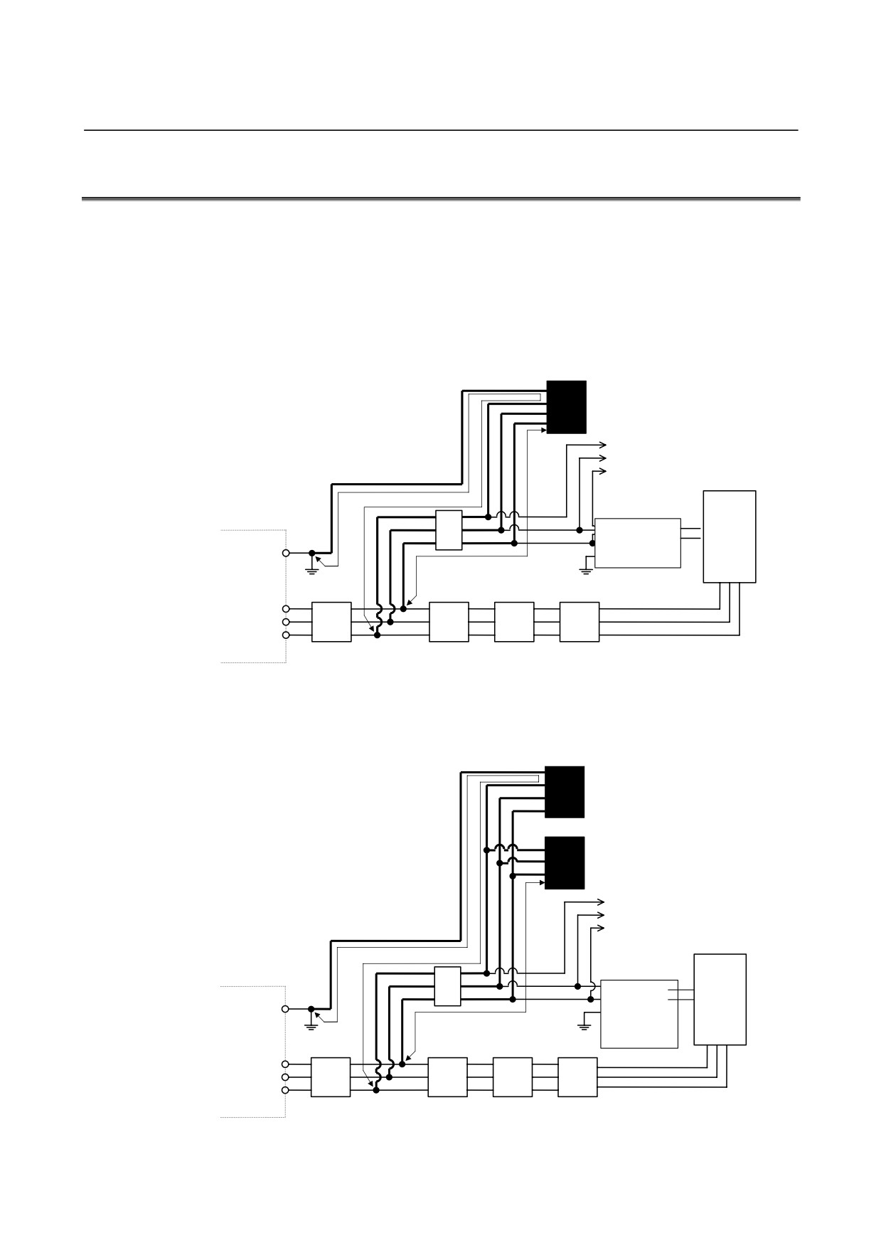
absorber between the power lines and between each power line and a
ground to protect the unit from a voltage surge caused by lightning.
How to install the surge absorber is shown below.
(1) Surge absorber for three-phase input
When using an integrated lightning surge absorber between the
power lines and between each power line and a ground
Lightning surge absorber between power
lines and between each power line and
ground (R.C.M-601BUZ-4)
To other units
(a)
Control power
(b)
input
Stabilized
power supply
G
βi SVPM
(24 VDC)
Circuit breaker 2
Ground plate
(5A)
Main circuit
R
power
200VAC
S
T
supply
input
Ground-fault circuit
Circuit
Magnetic
AC reactor
interrupter for power
breaker 1
contactor
magnetics cabinet
When using separate lightning surge absorbers between the power
lines and between each power line and a ground
Lightning surge absorber between
each power line and ground
(R.A.V-781BXZ-2)
Lightning surge absorber between
power lines (R.A.V-781BYZ-2)
To other units
(a)
Control
(b)
power supply
input
Stabilized
power supply
G
(24 VDC)
Circuit breaker
βi SVPM
2 (5A)
Ground
plate
Main circuit
R
power supply
AC200V
S
input
T
Ground-fault circuit interrupter Circuit
Magnetic
AC reactor
for power magnetics cabinet
breaker 1
contactor
- 121 -
6.INSTALLATION CONDITIONS AND NOTES SVPM
B-65322EN/02
WARNING
1
Make the wires shown with thick line in the above
diagram as short as possible in order to increase
the effect of the lightning surge absorber.
Wire Cross section : At least 2mm2
Length : Keep the total wire length (a+b) to
within 2m,where a = length of wire
used to connect lightning surge
absorber (1) b = length of wire used
to connect lightning surge absorber
(2)
2
When performing a dielectric strength test by
applying an overvoltage (such as 1000 or 1500
VAC) to a power line, remove lightning surge
absorber (2) so that it will not operate.
3
The circuit protector (5A) is intended to protect the
lines if a lightning surge absorber is damaged due
to a surge that is higher than the maximum
allowable voltage of the surge absorber.
4
Usually, no current flows through the lightning
surge absorbers. So the circuit protector (5A) may
be used also for other sections (such as power
supply module control power and spindle motor fan
power).
The
following table lists commercially available lightning surge
absorbers.
Table 6.4(a) Lightning surge absorbers (not complying with the relevant standards)
Manufacturer's
Maximum
Maximum
Lightning
Maximum allowable
specification
Clamp voltage
allowable surge
allowable surge
surge
circuit voltage
Okaya Electric
[V]±10%
current
voltage
absorber
[Vrms]
Industries
8/20µsec [A]
1.2/50µsec [V]
<1>
R・A・V-781BYZ-2
783
1000
12000
300
<2>
R・A・V-781BXZ-2A
783
1000
12000
300
Table 6.4(b) Lightning surge absorbers (complying with the relevant standards)
Manufacturer's
Maximum
Maximum
Lightning
Maximum allowable
specification
Clamp voltage
allowable surge
allowable surge
surge
circuit voltage
Okaya Electric
[V]±10%
current
voltage
absorber
[Vrms]
Industries
8/20µsec [A]
1.2/50µsec [V]
<1>
R・A・V-781BYZ-2
783
1000
12000
300
<2>
R・A・V-781BXZ-4
783
1000
12000
300
- 122 -
B-65322EN/02
SVPM
7.PROTECTIVE GROUNDING
7
PROTECTIVE GROUNDING
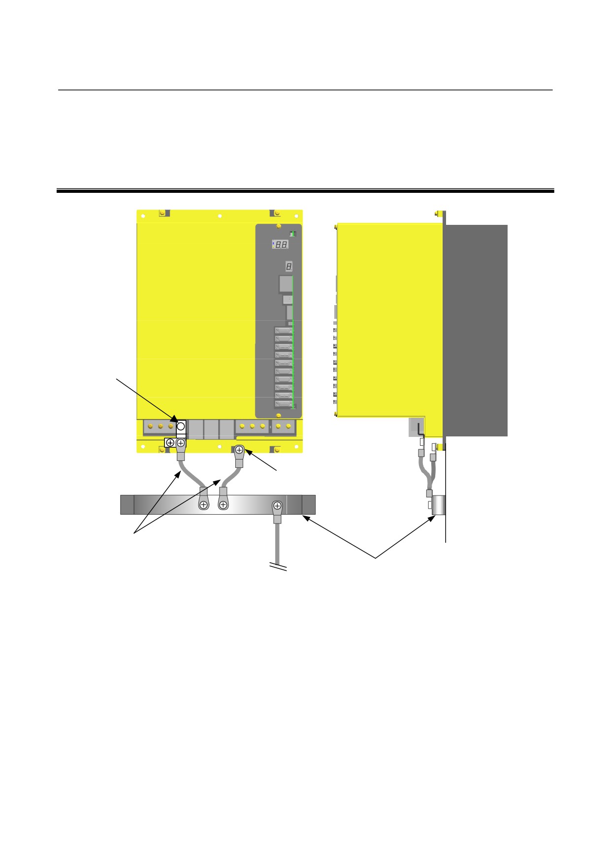
L-shaped
metal
plate (TB2
grounding
terminal)
Flange tapped hole
Use short cable.
Ground plate of cabinet
To system ground
- 123 -
8.EXTERNAL DIMENSIONS / PANEL CUT-OUT DRAWINGS / MAINTENANCE AREA SVPM B-65322EN/02
8
EXTERNAL DIMENSIONS / PANEL
CUT-OUT DRAWINGS / MAINTENANCE
AREA
- 124 -
B-65322EN/02 SVPM 8.EXTERNAL DIMENSIONS / PANEL CUT-OUT DRAWINGS / MAINTENANCE AREA
8.1
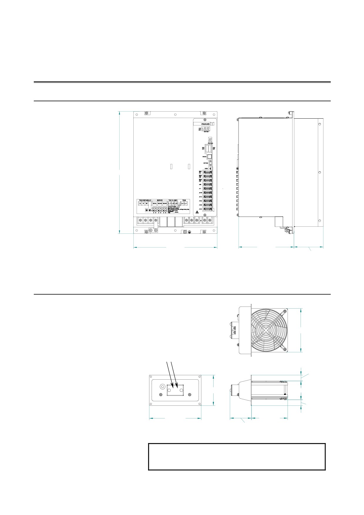
EXTERNAL DIMENSIONS
8.1.1
External Dimensions of SVPM
㪊㪏㪇 㫄㫄
㪉㪍㪇 㫄㫄
㪈㪎㪉 㫄㫄
㪐㪉㪅㪌 㫄㫄㩷㫄㪸㫏㪅
Weight : 14.8 kg
8.1.2
External Dimensions of Fan Unit (A06B-6134-K001)
㪈㪉㪇 㫄㫄
200VAC IN Note)
㩿 㪈㪌 㫄㫄㪀
㪏㪌 㫄㫄
㩿 㪌㪌 㫄㫄㪀
㩿 㪈㪌 㫄㫄㪀
㪈㪋㪌 㫄㫄
㪈㪇㪇 㫄㫄
㪍㪇 㫄㫄
Weight : 1.1kg
NOTE
Use a 2-A fuse or circuit breaker to prevent a
motor burnout.
- 125 -
8.EXTERNAL DIMENSIONS / PANEL CUT-OUT DRAWINGS / MAINTENANCE AREA SVPM B-65322EN/02
8.1.3
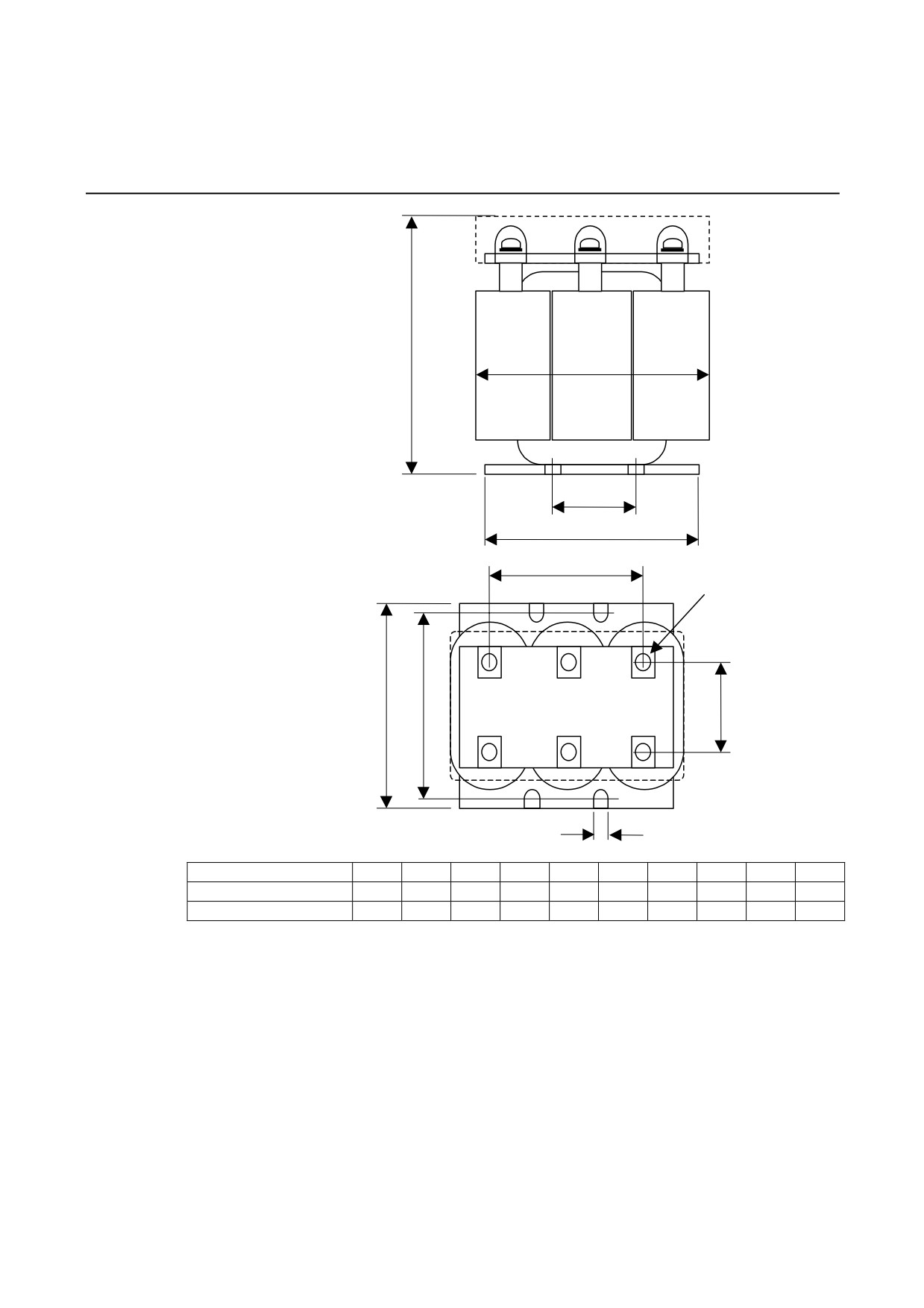
AC Reactor Unit
Max.B
H
D
A
F
M-
C
䌅
G
K
Applicable model
A
B
C
D
E
F
G
H
K
M-
For SVPM-5.5i, 11i
135
155
82
50
65
89
48
135
5
M5
For SVPM-15i
135
155
108
42
95
84
66
135
7.2
M5
- 126 -
B-65322EN/02 SVPM 8.EXTERNAL DIMENSIONS / PANEL CUT-OUT DRAWINGS / MAINTENANCE AREA
8.1.4
Power Transformer
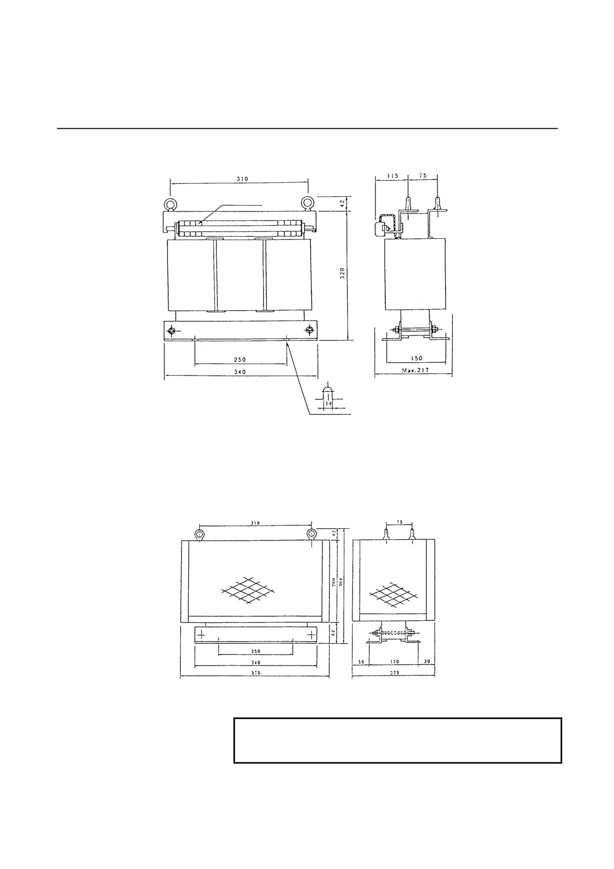
(a) For SVPM-5.5i (A06B-6052-J001)
Terminal M4
Outline Drawing of Power Transformer with no Cover
Outline Drawing of Power Transformer with Cover
NOTE
The four side panels are all meshed, while the top is
a solid plate.
- 127 -
8.EXTERNAL DIMENSIONS / PANEL CUT-OUT DRAWINGS / MAINTENANCE AREA SVPM B-65322EN/02
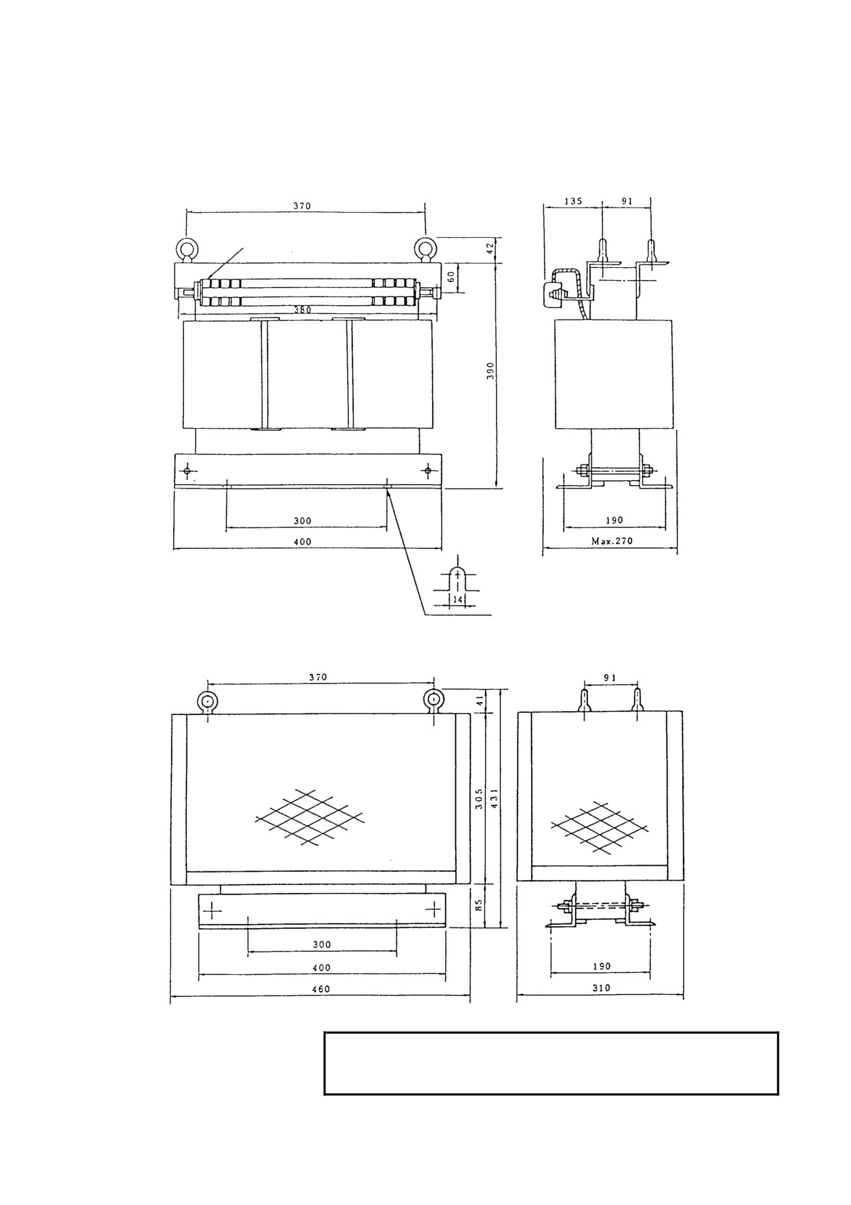
(b) For SVPM-11i
(A06B-6044-J006)
Terminal M6
Outline Drawing of Power Transformer with no Cover
Outline Drawing of Power Transformer with Cover
NOTE
The four side panels are all meshed, while the top is
a solid plate.
- 128 -
B-65322EN/02 SVPM 8.EXTERNAL DIMENSIONS / PANEL CUT-OUT DRAWINGS / MAINTENANCE AREA
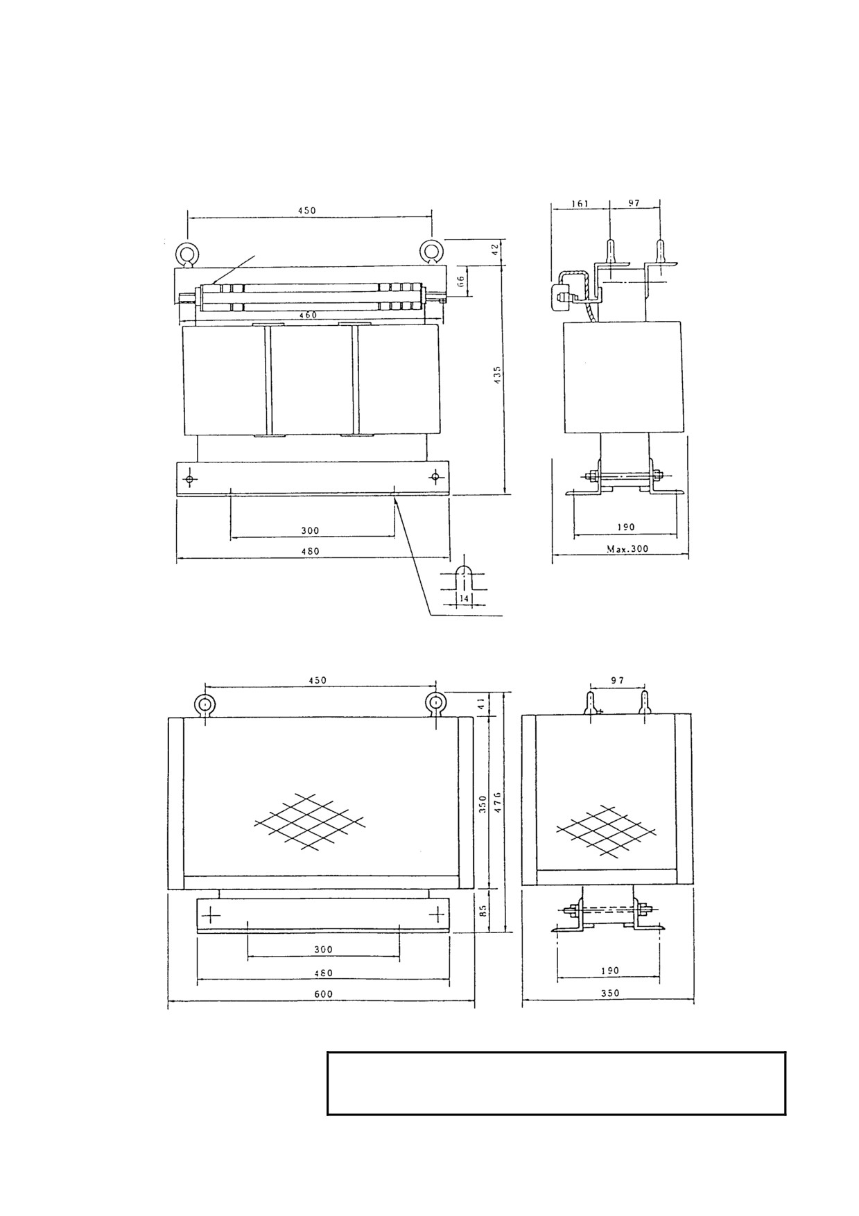
(c) For SVPM-15i (A06B-6044-J007)
Terminal M6
Outline Drawing of Power Transformer with no Cover
Outline Drawing of Power Transformer with Cover
NOTE
The four side panels are all meshed, while the top is
a solid plate.
- 129 -
8.EXTERNAL DIMENSIONS / PANEL CUT-OUT DRAWINGS / MAINTENANCE AREA SVPM B-65322EN/02
8.1.5
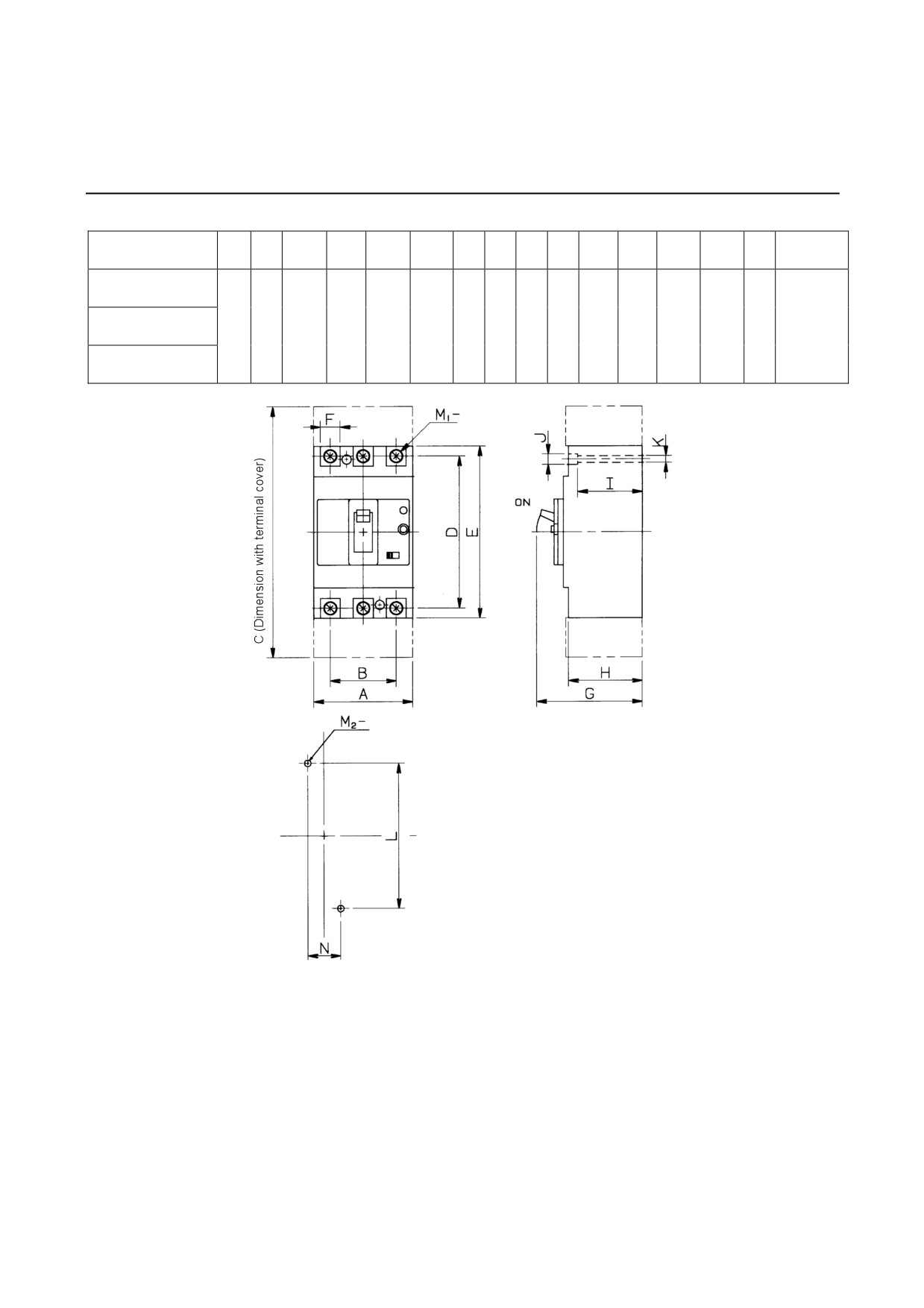
Circuit Breaker
Ordering
A
B
C
D
E
M1-
F
G
H
I
J
K
L
M2-
N
Mounting
drawing number
A06B-6077-K102
(For SVPM*-5.5i)
2
A06B-6077-K103
75
50
190
115
130
M8
17
80
56
49
φ8
φ5
110
M4
25
positions
(For SVPM*-11i)
(1)
A06B-6077-K104
(For SVPM*-15i)
Dimensions for mounting holes
- 130 -
B-65322EN/02 SVPM 8.EXTERNAL DIMENSIONS / PANEL CUT-OUT DRAWINGS / MAINTENANCE AREA
8.1.6
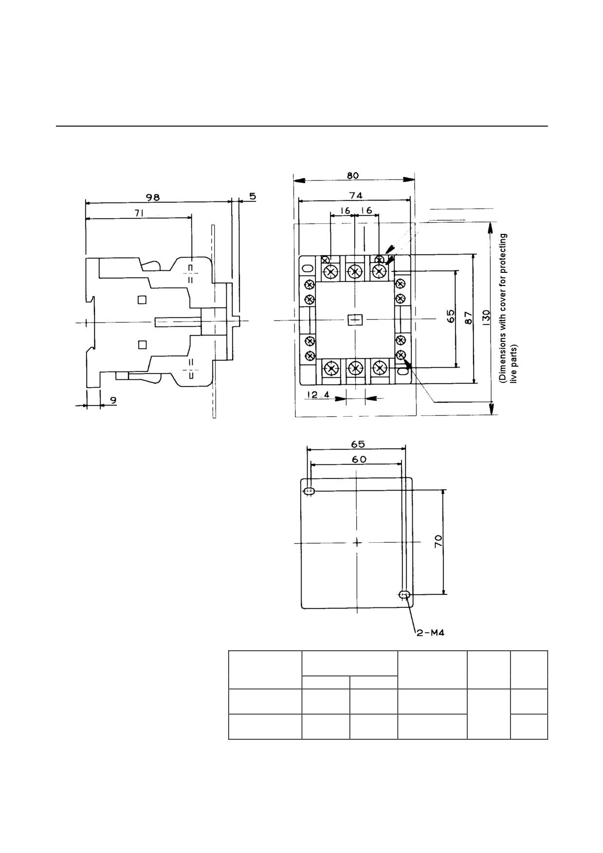
Magnetic Contactors
(a) A06B-6077-K122, A06B-6077-K123
(Dimensions with cover for protecting live parts)
Coil terminal M3.5
Main terminal M5
Auxiliary terminal M3.5
Dimensions for drilling mounting holes
Ordering
Fuji Electric part
Auxiliary
Operation coil
drawing
number
contact
Weight
voltage
number
Body
Cover
structure
A06B-6077-K122
SC-1N
SZ-1N/T
200V/50Hz
0.68Kg
(for SVPM*-5.5i)
2a2b
A06B-6077-K123
SC-2N
SZ-1N/T
200-220V/60Hz
0.68Kg
(for SVPM*-11i)
- 131 -
8.EXTERNAL DIMENSIONS / PANEL CUT-OUT DRAWINGS / MAINTENANCE AREA SVPM B-65322EN/02
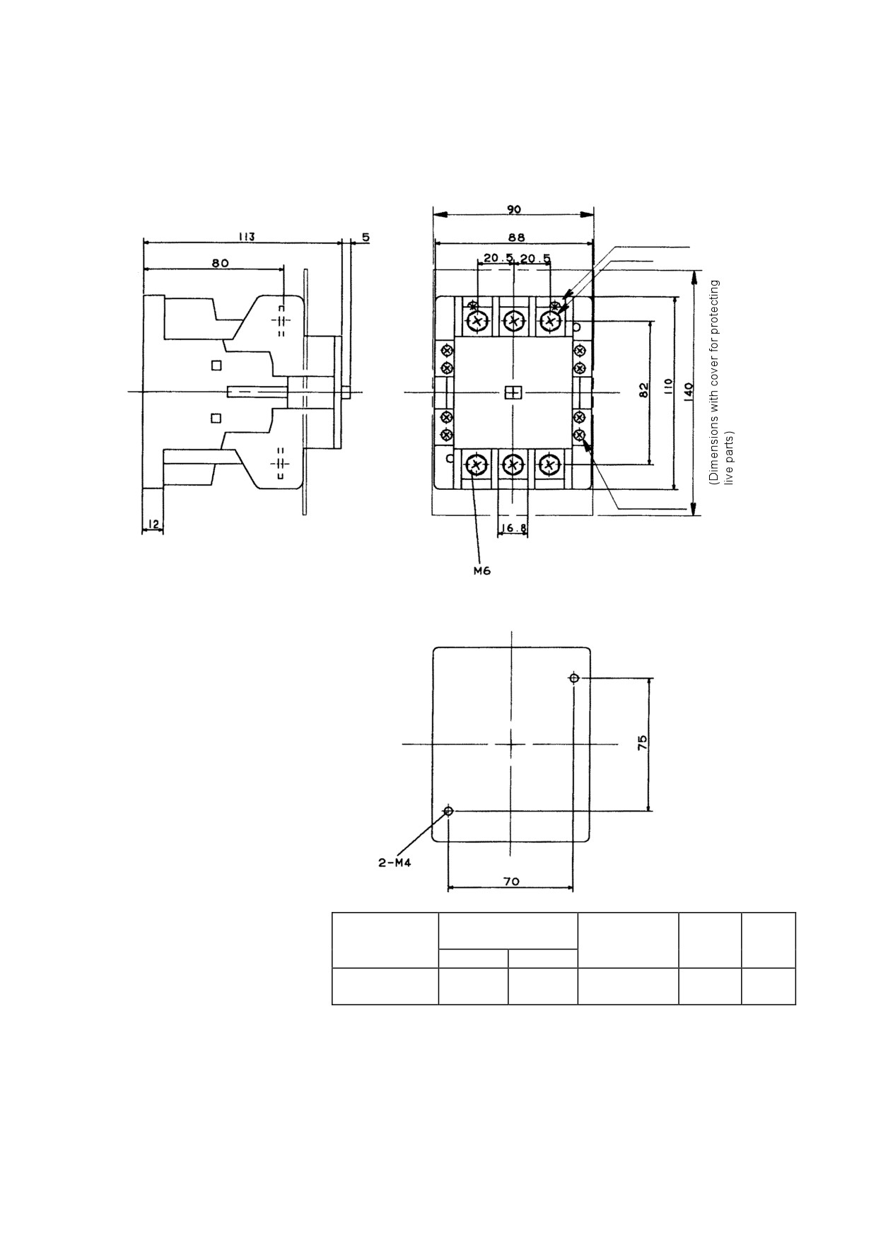
A06B-6077-K124
(Dimensions with cover for protecting live parts)
Coil terminal M3.5
Main terminal M6
Auxiliary terminal M3.5
Dimensions for drilling mounting holes
Ordering
Fuji Electric part
Auxiliary
Operation coil
drawing
number
contact
Weight
voltage
number
Body
Cover
structure
A06B-6077-K124
200V/50Hz
SC-2SN
SZ-2SN/T
2a2b
1.3Kg
(for SVPM*-15i)
200-220V/60Hz
- 132 -
B-65322EN/02 SVPM 8.EXTERNAL DIMENSIONS / PANEL CUT-OUT DRAWINGS / MAINTENANCE AREA
8.1.7
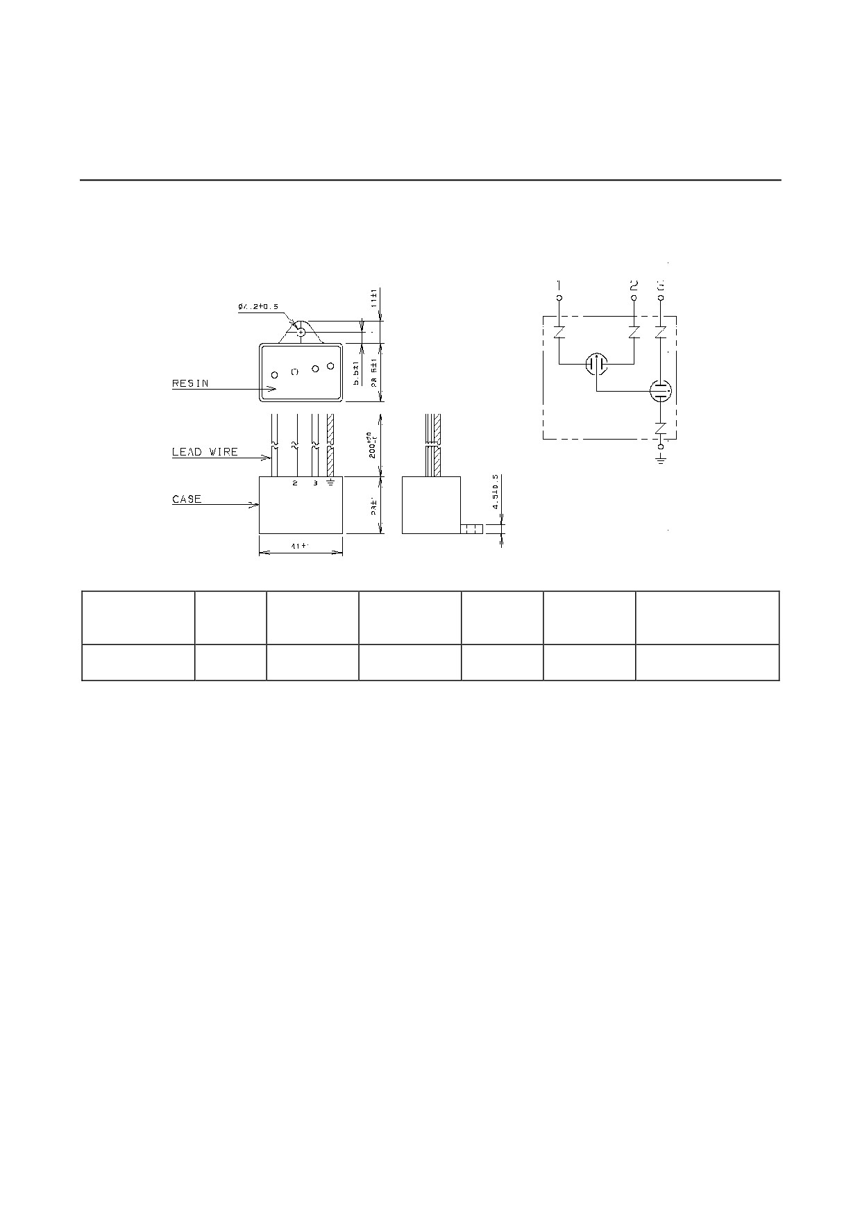
Lightning Surge Protector
(a) A06B-6077-K144
Connection diagram
Surge
Surge
Maximum surge
Rated
AC discharge
Specification
Clamp voltage
withstand
withstand
discharge start
voltage
start voltage
current
voltage
voltage
560VAC
2000V
2500A
20kV
2kV
R⋅C⋅M-601BUZ-4
250VAC
±20%(Ua)
±10%(V1.0)
(8/20µS)
(1.2/50µS)
(1.2/50µS)
- 133 -
8.EXTERNAL DIMENSIONS / PANEL CUT-OUT DRAWINGS / MAINTENANCE AREA SVPM B-65322EN/02
8.2
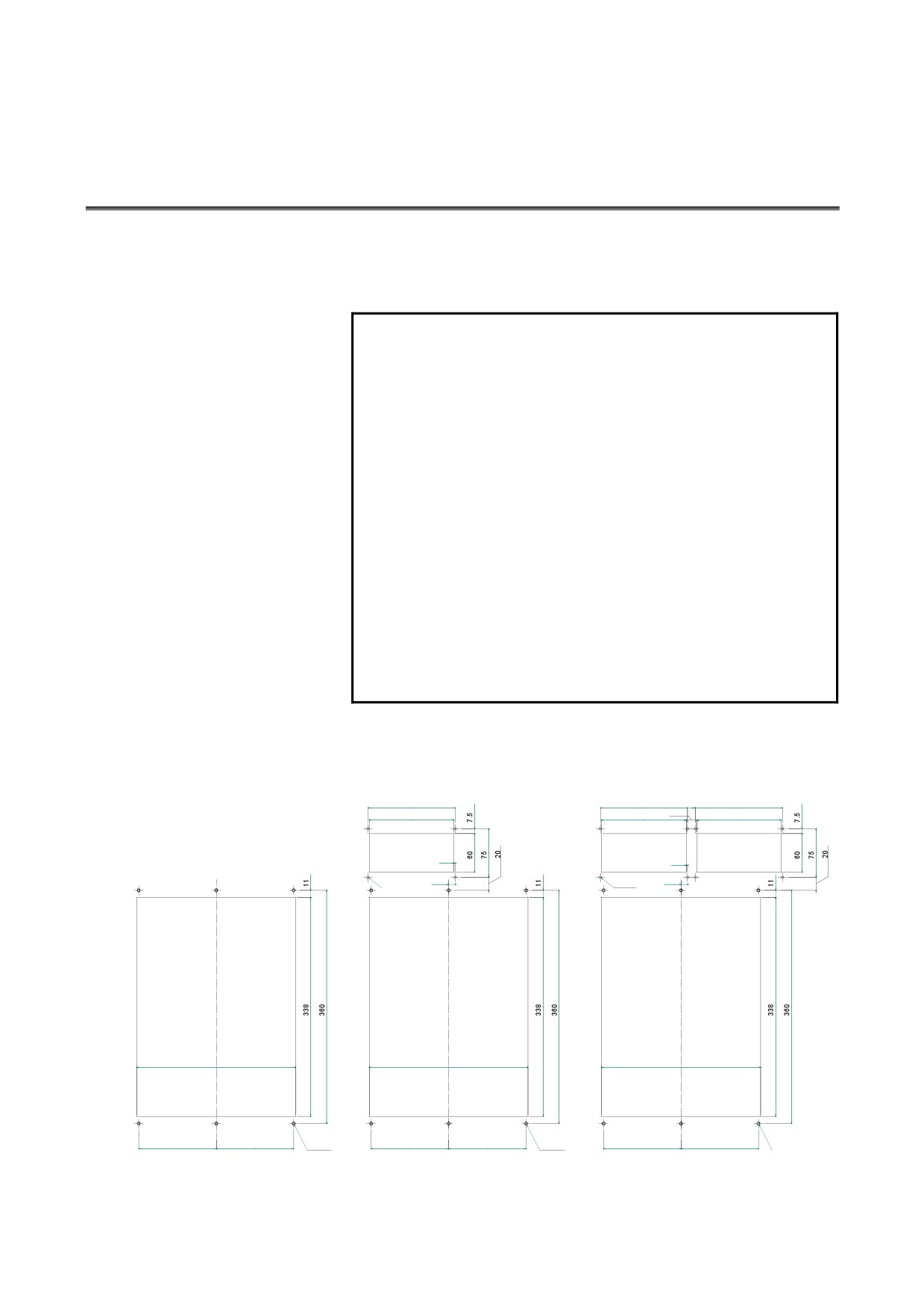
PANEL CUT-OUT DRAWINGS
Panel cut-outs that apply when a FANUC fan unit (A06B-6134-K001)
is used and when not used are shown below. A fan unit can be
placed either on top of or below the servo amplifier.
NOTE
1 Attach the accompanying gasket around the panel
cut-out to prevent oil and dust from getting into it.
2 Reinforce the right and left sides of the panel
cut-out in the power magnetics cabinet by using
fittings such as angles to maintain satisfactory
contact between the power magnetics cabinet and
the amplifier.
3 Placing a FANUC fan unit on top of the servo
amplifier requires installing a duct.
Refer to the “Example Duct Structure for Using a
FANUC Fan Unit (A06B-6134-K001)” for
descriptions about the structure of the duct.
4 Placing a FANUC fan unit below the servo amplifier
does not require installing a duct.
If no FANUC fan unit is used, the user is requested
to install a fan motor that can generate an air flow
of at least 2 m/s at the heat sink.
(1)
When no FANUC fan unit
(2) When one FANUC fan unit is used
(3) When two FANUC fan units are used
is used
(placed on top of the servo
(placed on top of the servo amplifier)
amplifier)
135
135
12
135
131
131
16
131
2
2
4-M4
10
4-M4
10
246
246
246
120
120
6-M5
120
120
6-M5
120
120
6-M5
- 134 -
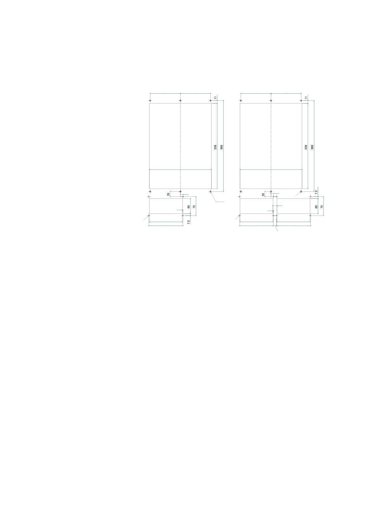
B-65322EN/02 SVPM 8.EXTERNAL DIMENSIONS / PANEL CUT-OUT DRAWINGS / MAINTENANCE AREA
(4) When one FANUC fan unit is used
(5) When two FANUC fan units are
(placed below the servo amplifier)
used (placed below the servo
amplifier)
120
120
120
120
246
246
10
10
6-M5
6-M5
16
2
2
4-M4
4-M4
131
131
131
135
135
135
12
- 135 -