FANUC AC Servo Amplifiers βi Series. Description Manual (B-65322EN/02) - page 3
B-65322EN/02
SVM
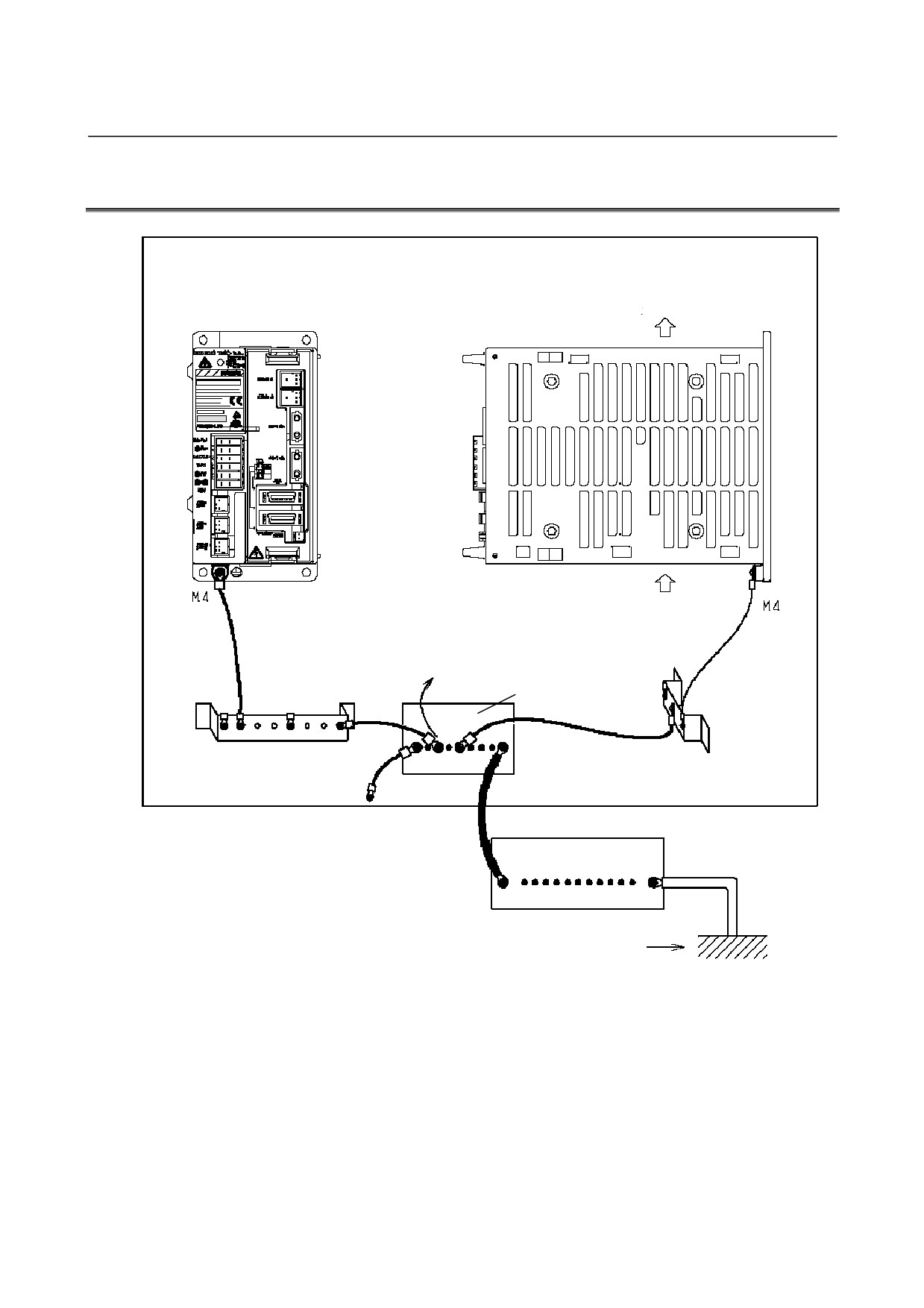
7.PROTECTIVE GROUNDING
7.1
SVM1-4i and SVM1-20i (FSSB Interface)
Servo unit
Servo unit
(Front view)
(Side view)
Air out
Air in
To be as short
as possible
To other ground plates
Distribution panel in
cabinet
Ground plate
Ground plate
Connected to cabinet
External distribution panel
Class-3 ground or higher
- 43 -
7.PROTECTIVE GROUNDING
SVM
B-65322EN/02
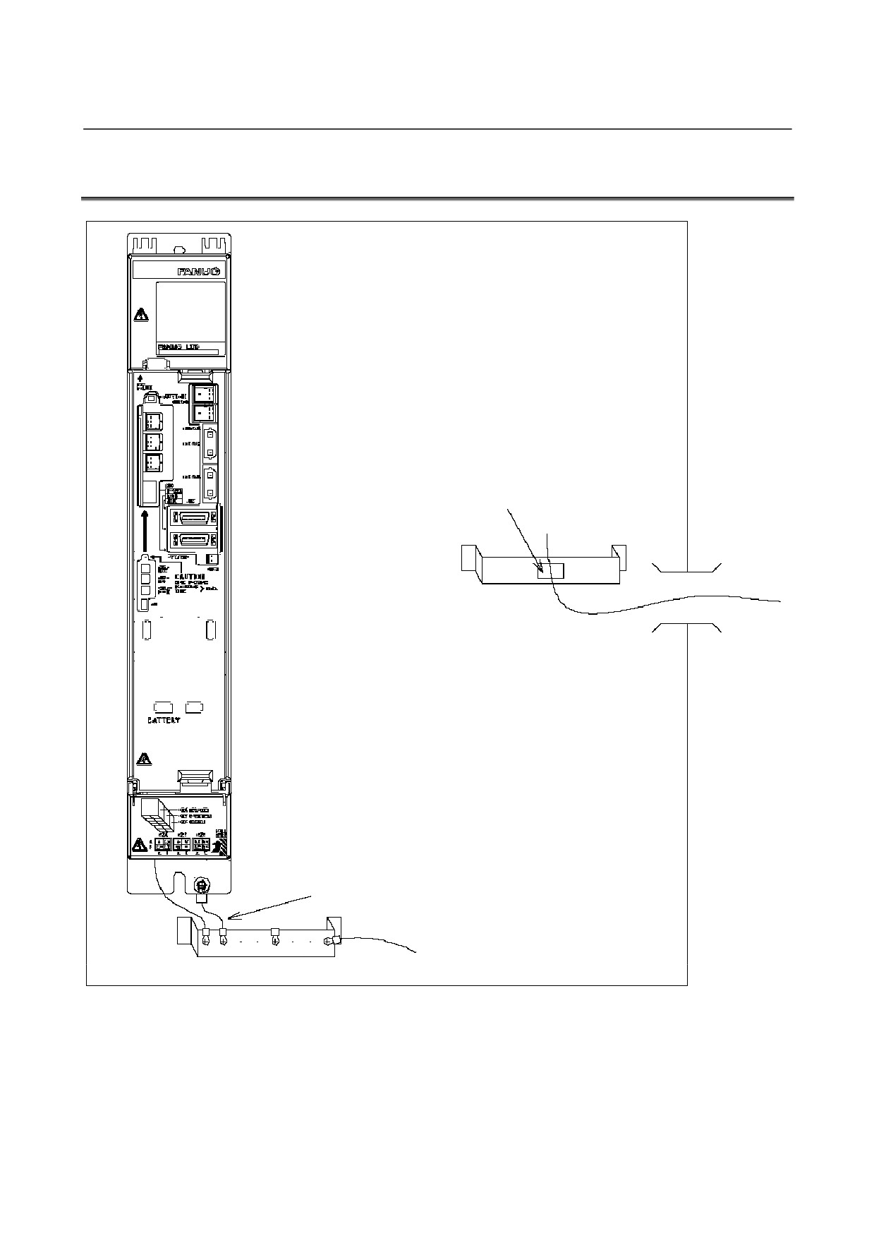
7.2
SVM1-40i and SVM1-80i (FSSB Interface)
Clamp shield
Inlet
External shielded cable
To be as short as possible
Ground plate
To system ground
- 44 -
B-65322EN/02 SVM
8.EXTERNAL DIMENSIONS / PANEL CUT-OUT DRAWINGS / MAINTENANCE AREA
8
EXTERNAL DIMENSIONS / PANEL
CUT-OUT DRAWINGS / MAINTENANCE
AREA
- 45 -
8.EXTERNAL DIMENSIONS / PANEL CUT-OUT DRAWINGS / MAINTENANCE AREA SVM B-65322EN/02
8.1
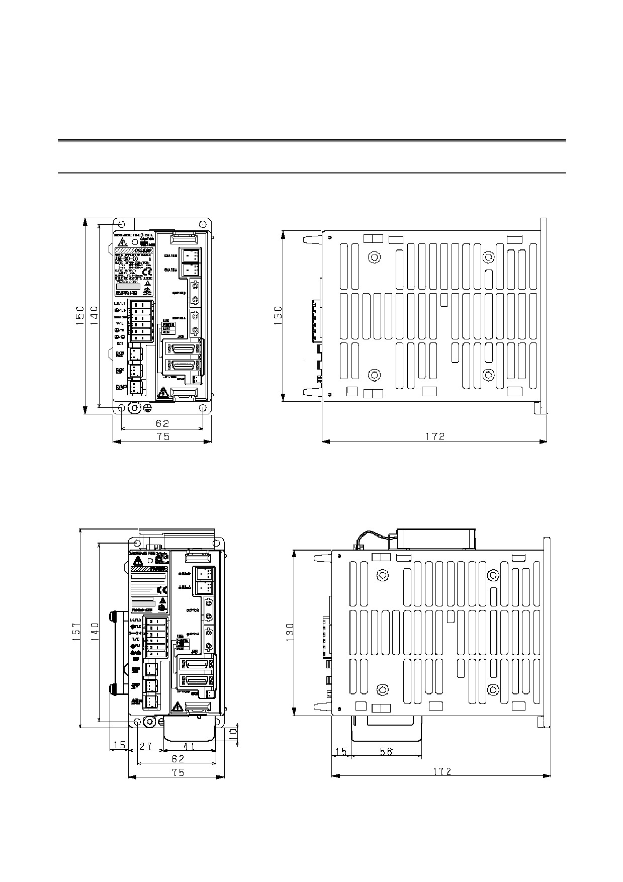
EXTERNAL DIMENSIONS
8.1.1
External Dimensions of SVM1-4i and SVM1-20i
Amplifier alone
Weight : 1.2kg
Amplifier with a regenerative resistor, fan motor, and
battery attached
Weight : 1.3kg
- 46 -
B-65322EN/02 SVM
8.EXTERNAL DIMENSIONS / PANEL CUT-OUT DRAWINGS / MAINTENANCE AREA
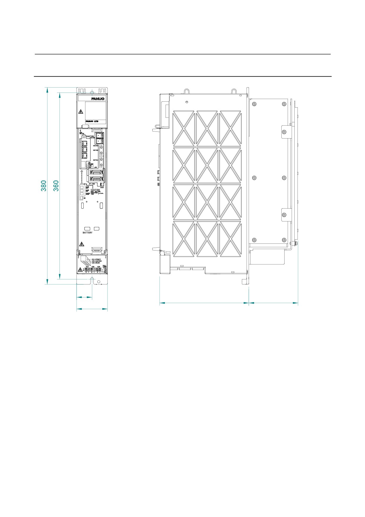
8.1.2
External Dimensions of SVM1-40i and SVM1-80i
Yamanashi 401-0597 JAPAN
30
172
100 max.
60
Weight : 3.9kg
- 47 -
8.EXTERNAL DIMENSIONS / PANEL CUT-OUT DRAWINGS / MAINTENANCE AREA SVM B-65322EN/02
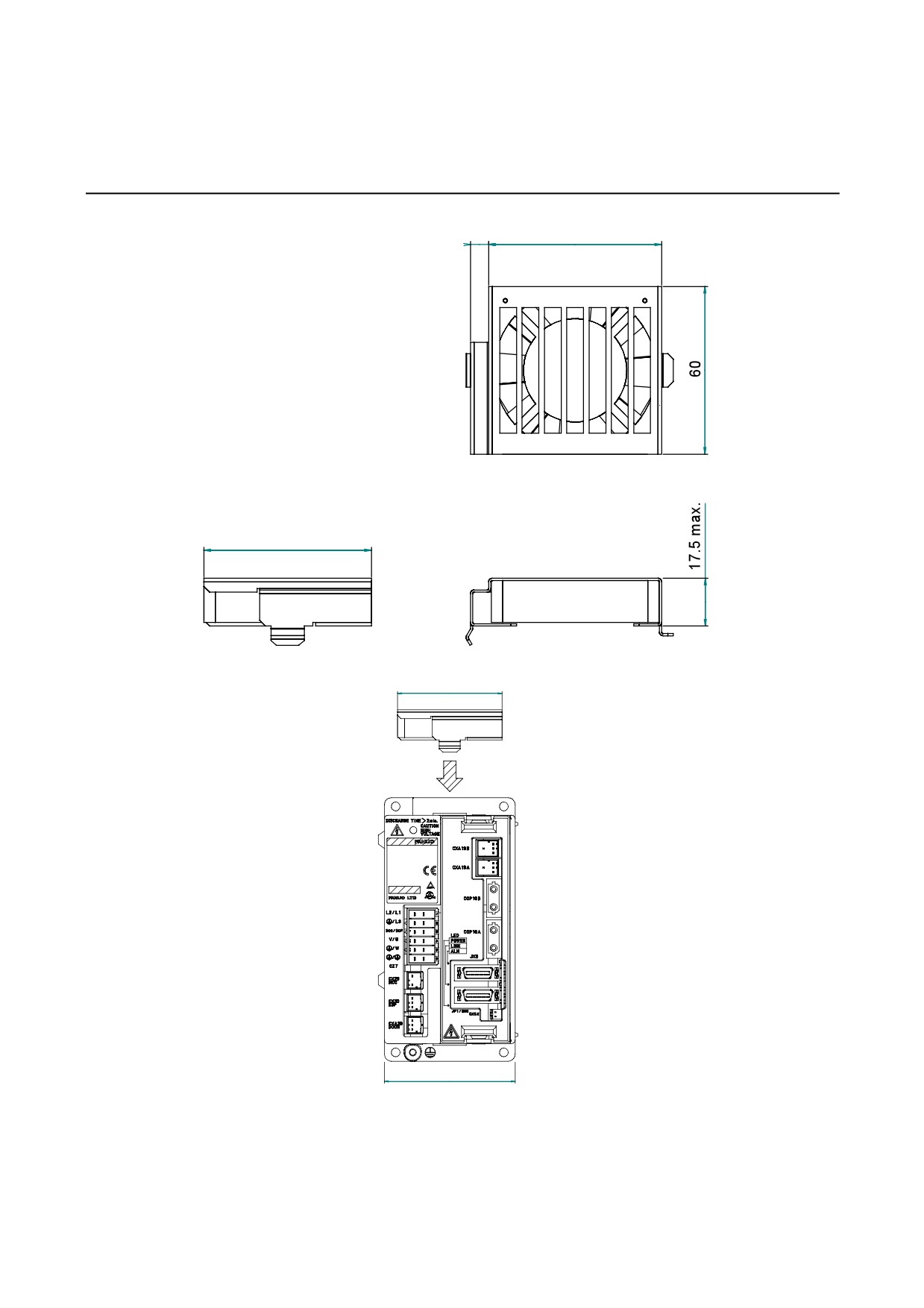
8.1.3
External Dimensions of Fan Unit (A06B-6134-K003)
6.5
62
60
60
Yamanashi 401-0 597 JAPA N
m ade in JAPAN
75
- 48 -
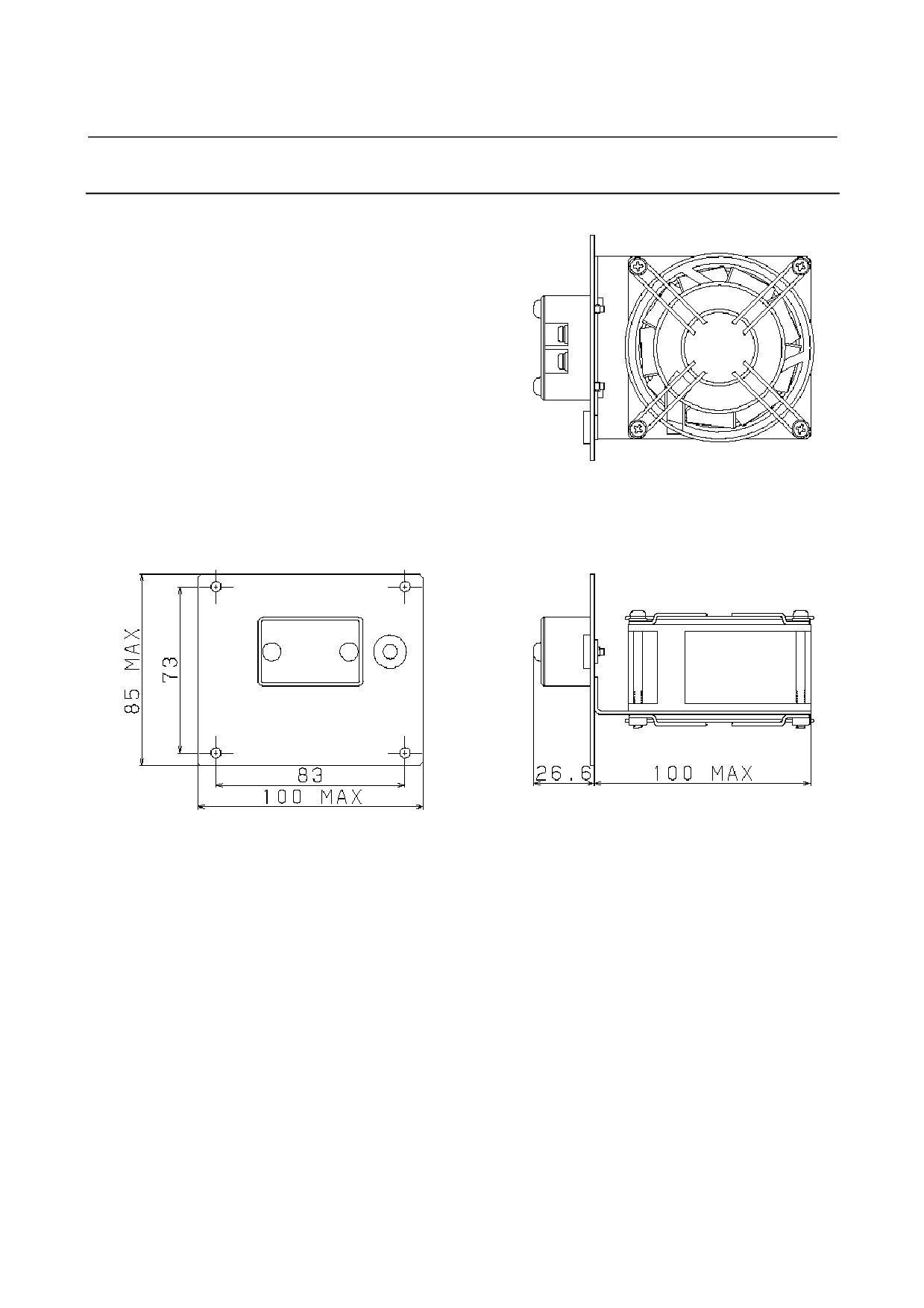
B-65322EN/02 SVM
8.EXTERNAL DIMENSIONS / PANEL CUT-OUT DRAWINGS / MAINTENANCE AREA
8.1.4
External Dimensions of Fan Unit (A06B-6134-K002)
- 49 -
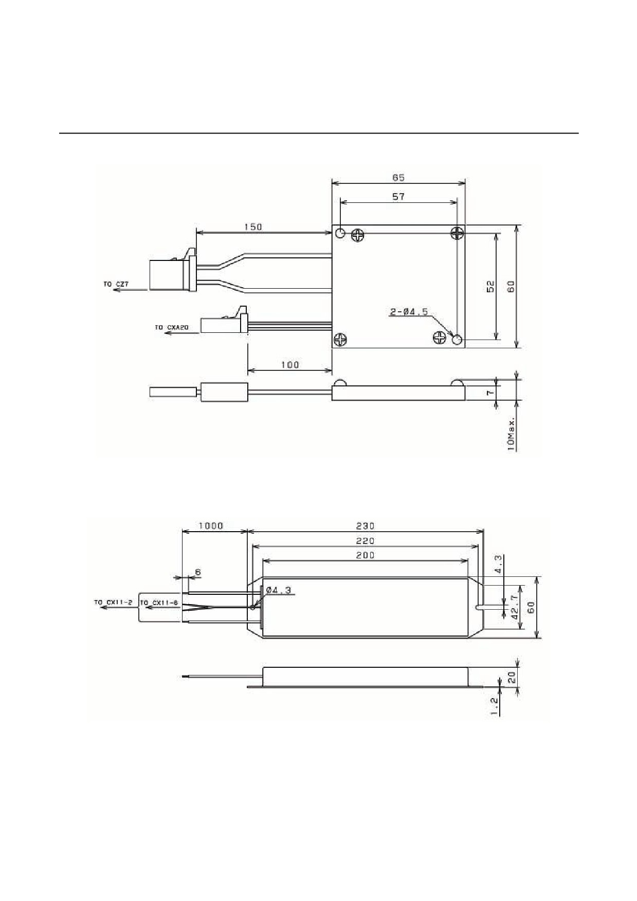
8.EXTERNAL DIMENSIONS / PANEL CUT-OUT DRAWINGS / MAINTENANCE AREA SVM B-65322EN/02
8.1.5
Discharge Resistor
A06B-6130-H401
Weight:
0.07 kg
A06B-6130-H402
Weight:
0.5 kg
- 50 -
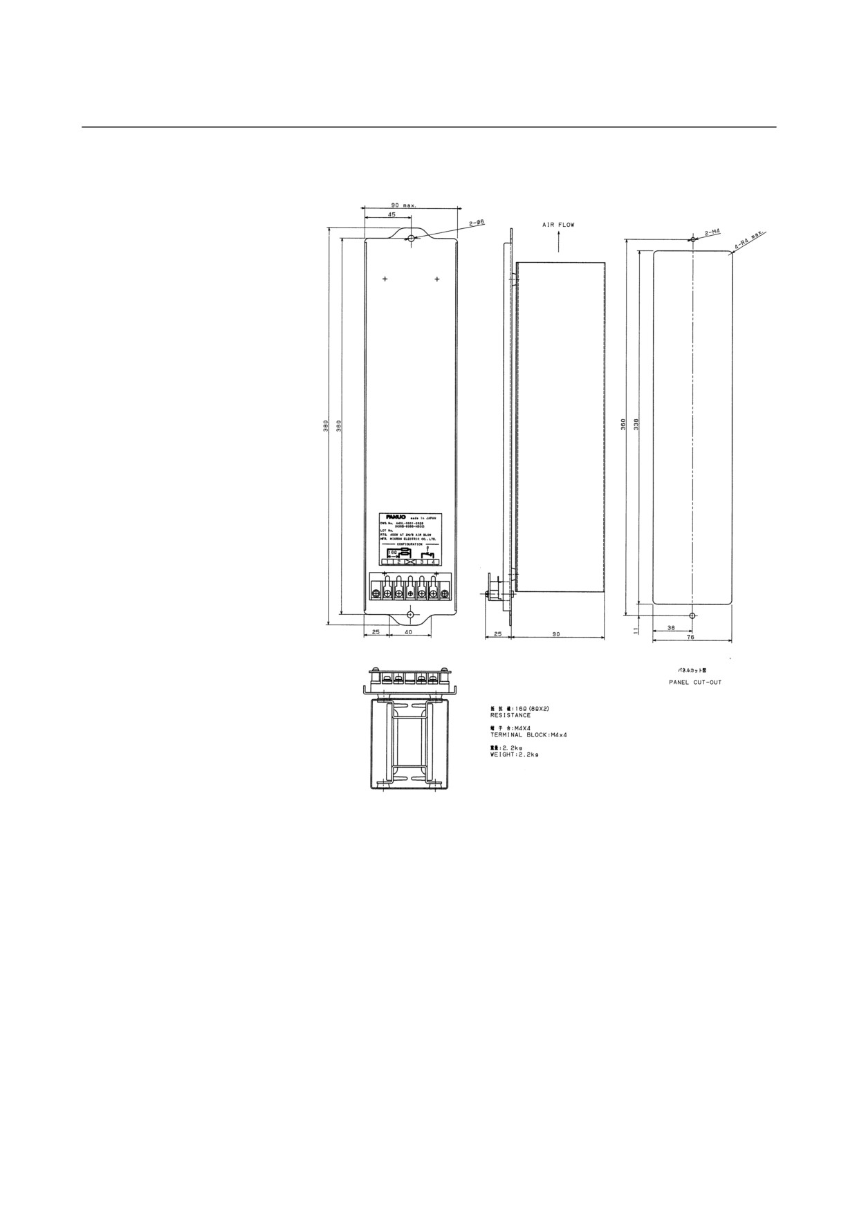
B-65322EN/02 SVM
8.EXTERNAL DIMENSIONS / PANEL CUT-OUT DRAWINGS / MAINTENANCE AREA
A06B-6089-H500
- 51 -
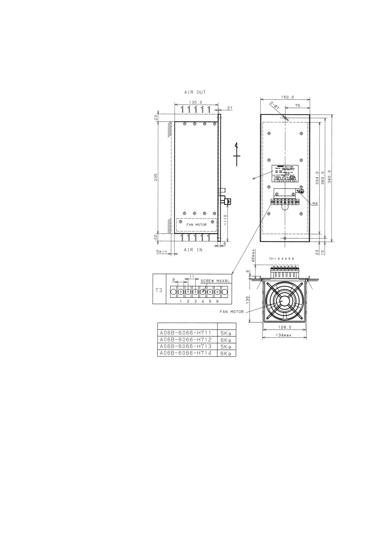
8.EXTERNAL DIMENSIONS / PANEL CUT-OUT DRAWINGS / MAINTENANCE AREA SVM B-65322EN/02
A06B-6089-H713 to H714
(Pay attention to high temperature)
Up
Installation direction
Label
Packing
Packing
Drawing No.
Weight
- 52 -
B-65322EN/02 SVM
8.EXTERNAL DIMENSIONS / PANEL CUT-OUT DRAWINGS / MAINTENANCE AREA
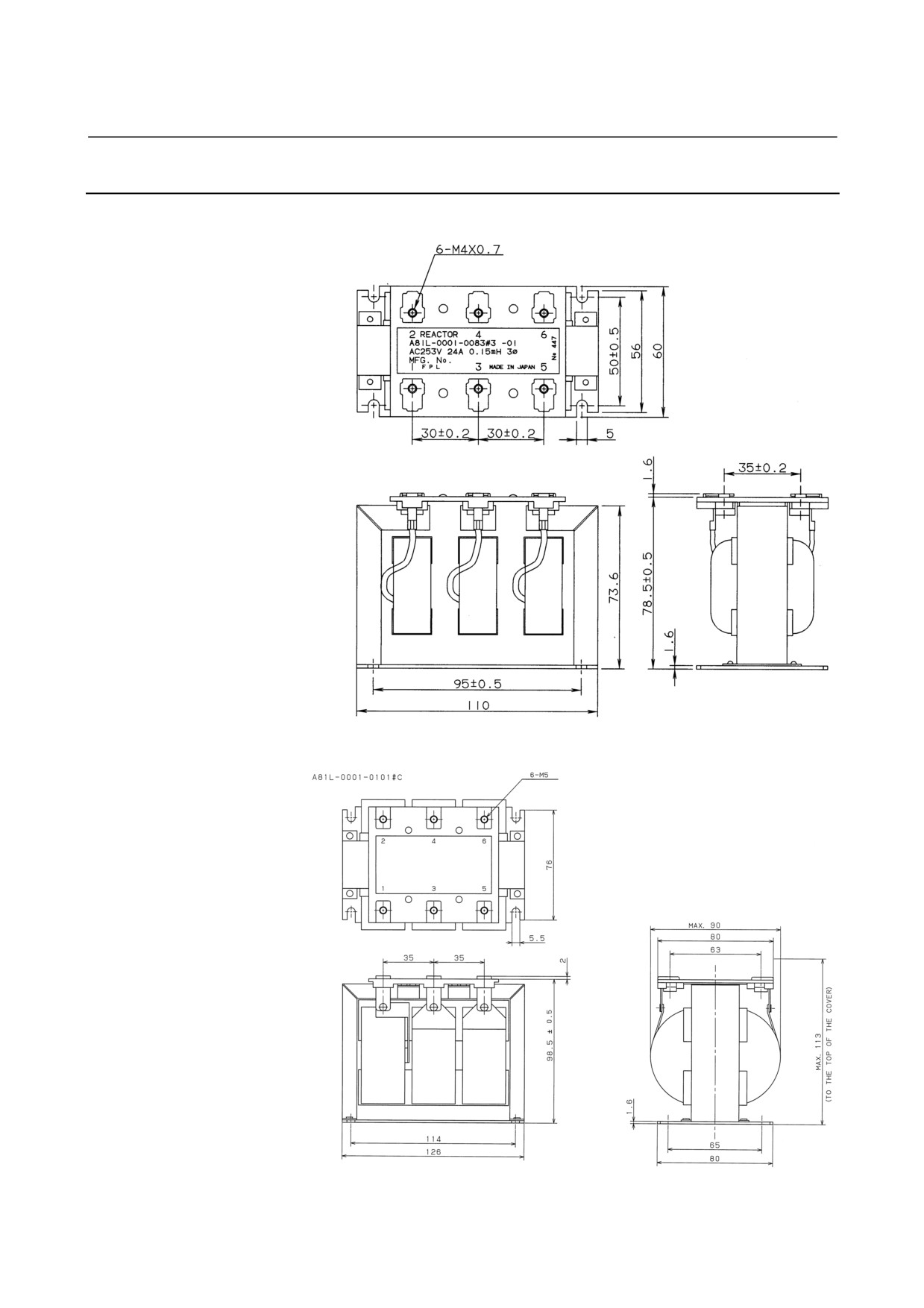
8.1.6
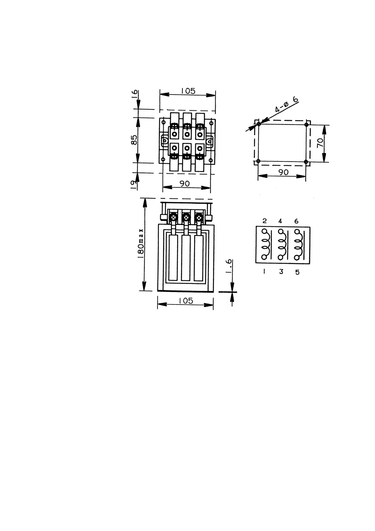
AC Line Filter
A81L-0001-0083#3C
A81L-0001-0101#C
- 53 -
8.EXTERNAL DIMENSIONS / PANEL CUT-OUT DRAWINGS / MAINTENANCE AREA SVM B-65322EN/02
A81L-0001-0102
- 54 -
B-65322EN/02 SVM
8.EXTERNAL DIMENSIONS / PANEL CUT-OUT DRAWINGS / MAINTENANCE AREA
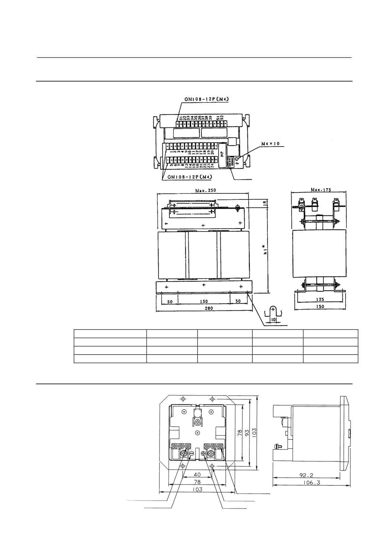
8.1.7
Transformer for Exports
Drawing No.
A80L-0022-0005
A80L-0024-0006
A80L-0026-0003
A80L-0028-0001
Type (name)
SAE
SBE
SCE
SDE
Weight
21 kg
27 kg
36 kg
42 kg
hl* (transformer height)
217 mm max
217 mm max
247 mm max
247 mm max
8.1.8
Battery Case
3-M3 (positive polarity)
M3 (negative polarity)
Countersinking for 4-M4
Negative polarity indication
Positive polarity indication
- 55 -
8.EXTERNAL DIMENSIONS / PANEL CUT-OUT DRAWINGS / MAINTENANCE AREA SVM B-65322EN/02
8.1.9
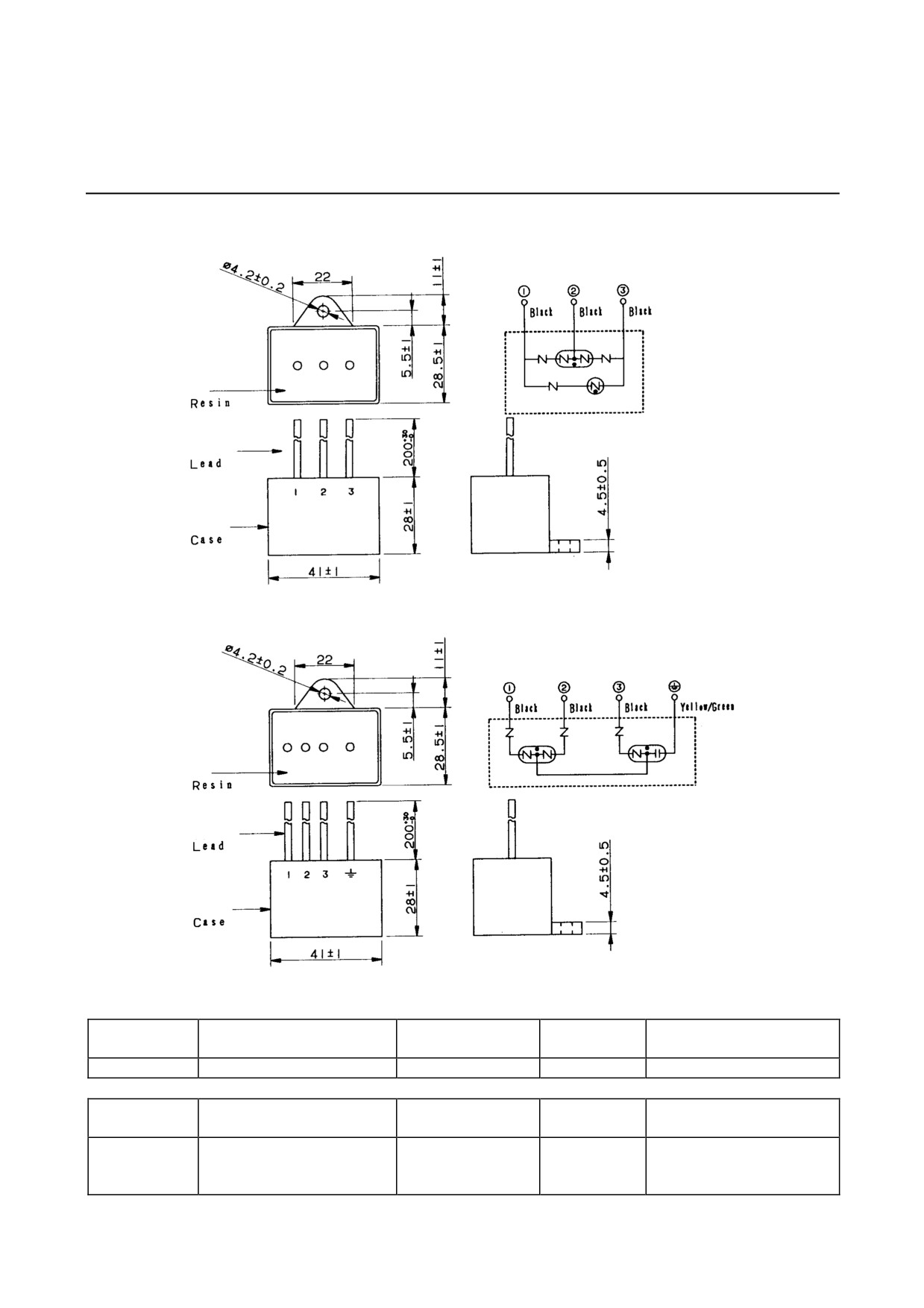
Lightning Surge Absorbers
(a) A06B-6077-K142
Connection
diagram
(1) Between power lines:
RAV-781BYZ-2
Connection
diagram
(2) Between each power line and ground: RAV-781BXZ-4
Withstanding
Specification
Rated voltage
Clamp voltage
Withstanding surge voltage
surge current
R⋅A⋅V-781BYZ-2
250 VAC
783 VDC±10%(V1.0)
2500A(8/20µS)
20kV(1.2/50µS)
AC discharge start
Withstanding
Maximum surge discharge
Specification
Rated voltage
voltage
surge current
start voltage
430 VAC between lines, 250
R⋅A⋅V-781BXZ-4
VAC between each line and
700 VAC±20%(Ua)
2500A(8/20µS)
2.0kV(1.2/50µS)
ground
- 56 -
B-65322EN/02 SVM
8.EXTERNAL DIMENSIONS / PANEL CUT-OUT DRAWINGS / MAINTENANCE AREA
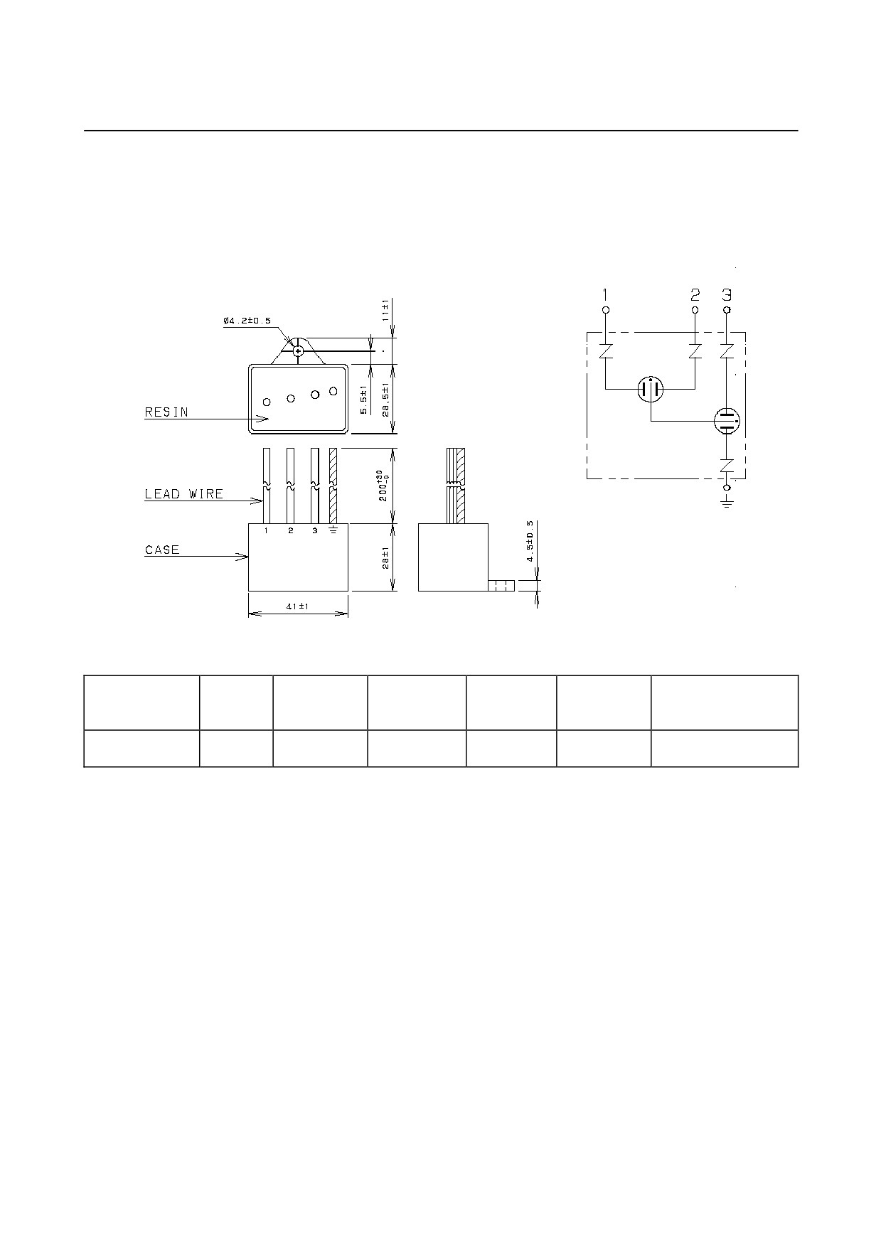
(b)A06B-6077-K144
Circuit
diagram
Maximum surge
Rated
AC discharge
Withstanding
Withstanding
Specification
Clamp voltage
discharge start
voltage
start voltage
surge current
surge voltage
voltage
560 VAC
2000V
2500A
20kV
2kV
R⋅C⋅M-601BUZ-4
250 VAC
±20%(Ua)
±10%(V1.0)
(8/20µS)
(1.2/50µS)
(1.2/50µS)
- 57 -
8.EXTERNAL DIMENSIONS / PANEL CUT-OUT DRAWINGS / MAINTENANCE AREA SVM B-65322EN/02
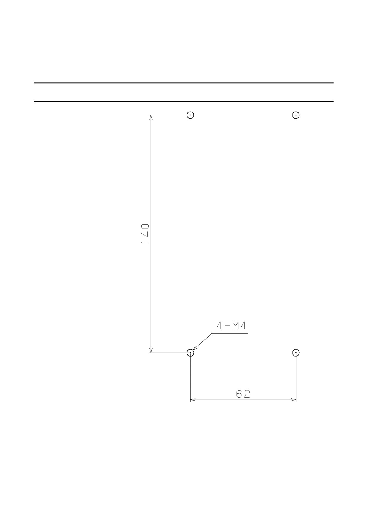
8.2
PANEL CUT-OUT DRAWINGS
8.2.1
SVM1-4i and SVM1-20i
- 58 -
B-65322EN/02 SVM
8.EXTERNAL DIMENSIONS / PANEL CUT-OUT DRAWINGS / MAINTENANCE AREA
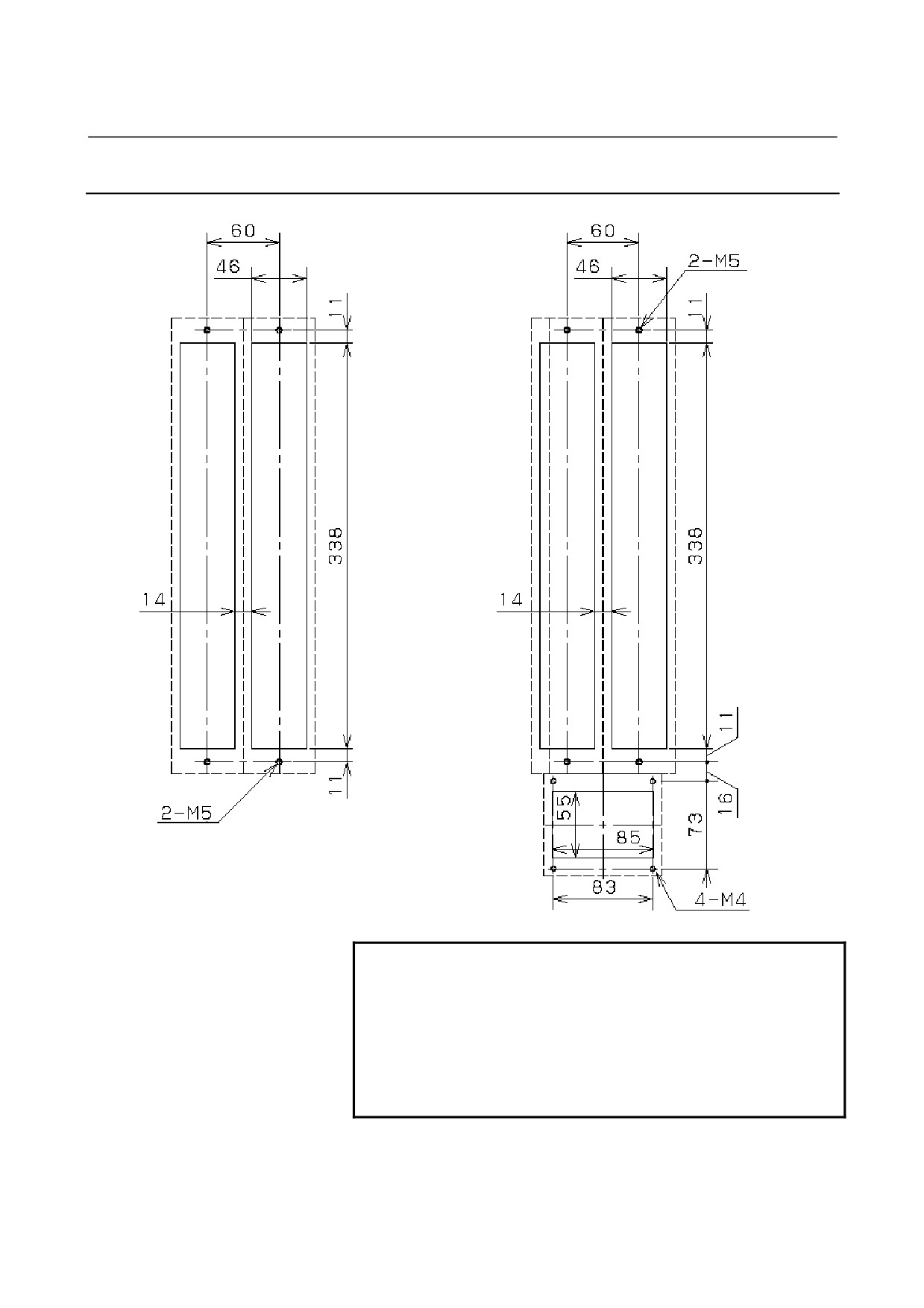
8.2.2
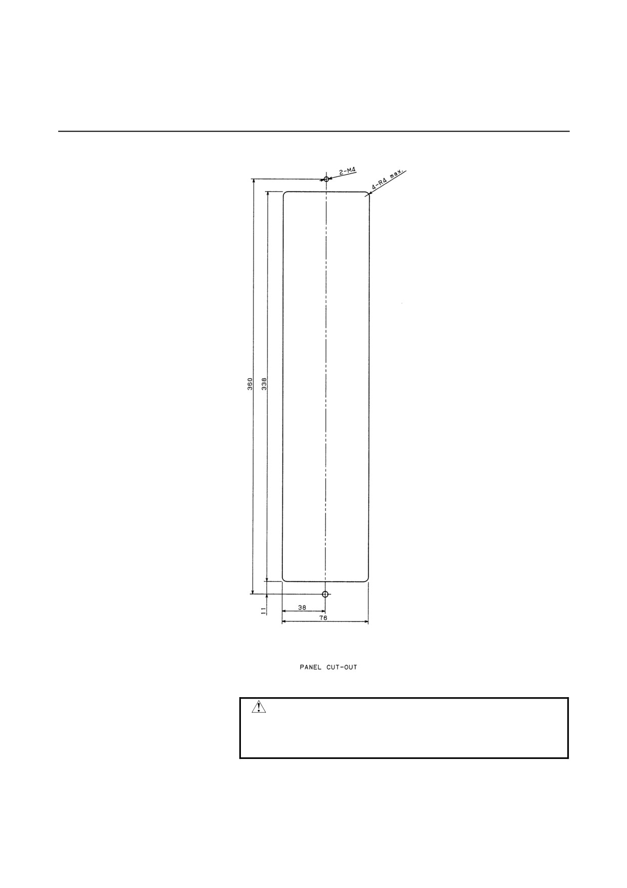
SVM1-40i and SVM1-80i
NOTE
Attach the accompanying gasket around the panel
cut-out to prevent oil and dust from getting into it.
Reinforce the right and left sides of the panel
cut-out in the power magnetics cabinet by using
fittings such as angles to maintain satisfactory
contact between the power magnetics cabinet and
the amplifier.
- 59 -
8.EXTERNAL DIMENSIONS / PANEL CUT-OUT DRAWINGS / MAINTENANCE AREA SVM B-65322EN/02
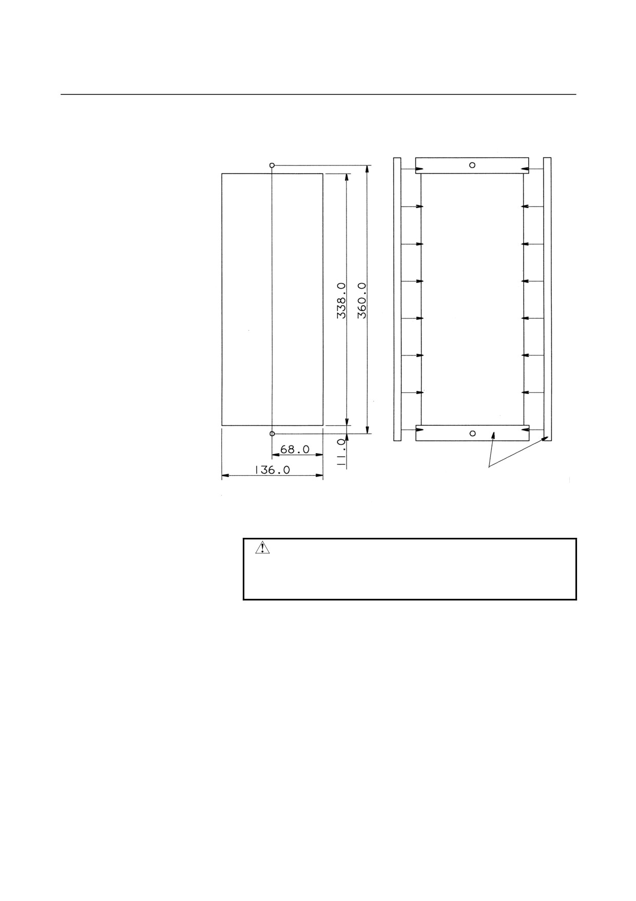
8.2.3
Discharge Resistor
A06B-6089-H500
CAUTION
Attach the packing (acrylonitrile-butadiene rubber,
NBR (soft type)) to prevent oil and dust from
getting into the resistor.
- 60 -
B-65322EN/02 SVM
8.EXTERNAL DIMENSIONS / PANEL CUT-OUT DRAWINGS / MAINTENANCE AREA
A06B-6089-H713 to H714
Panel cut-out
Packing (supplied)
Panel cut-out
CAUTION
Attach the packing (acrylonitrile-butadiene rubber,
NBR (soft type)) to prevent oil and dust from
getting into the resistor.
- 61 -
8.EXTERNAL DIMENSIONS / PANEL CUT-OUT DRAWINGS / MAINTENANCE AREA SVM B-65322EN/02
8.3
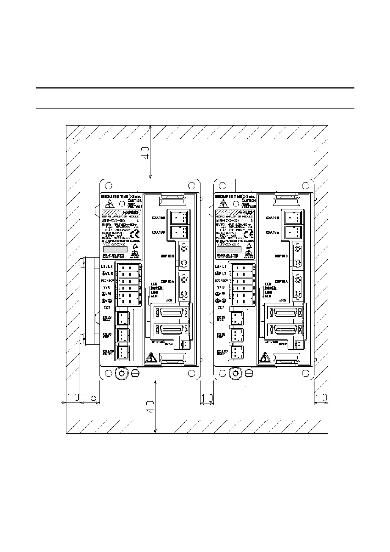
MAINTENANCE AREA
8.3.1
Maintenance Area for the SVM1-4i and SVM1-20i
- 62 -
B-65322EN/02 SVM
8.EXTERNAL DIMENSIONS / PANEL CUT-OUT DRAWINGS / MAINTENANCE AREA
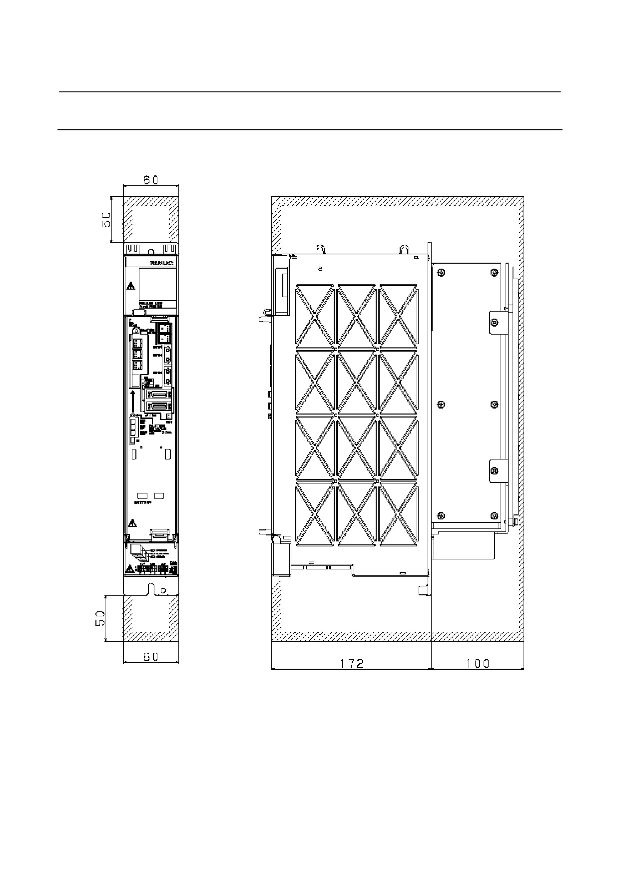
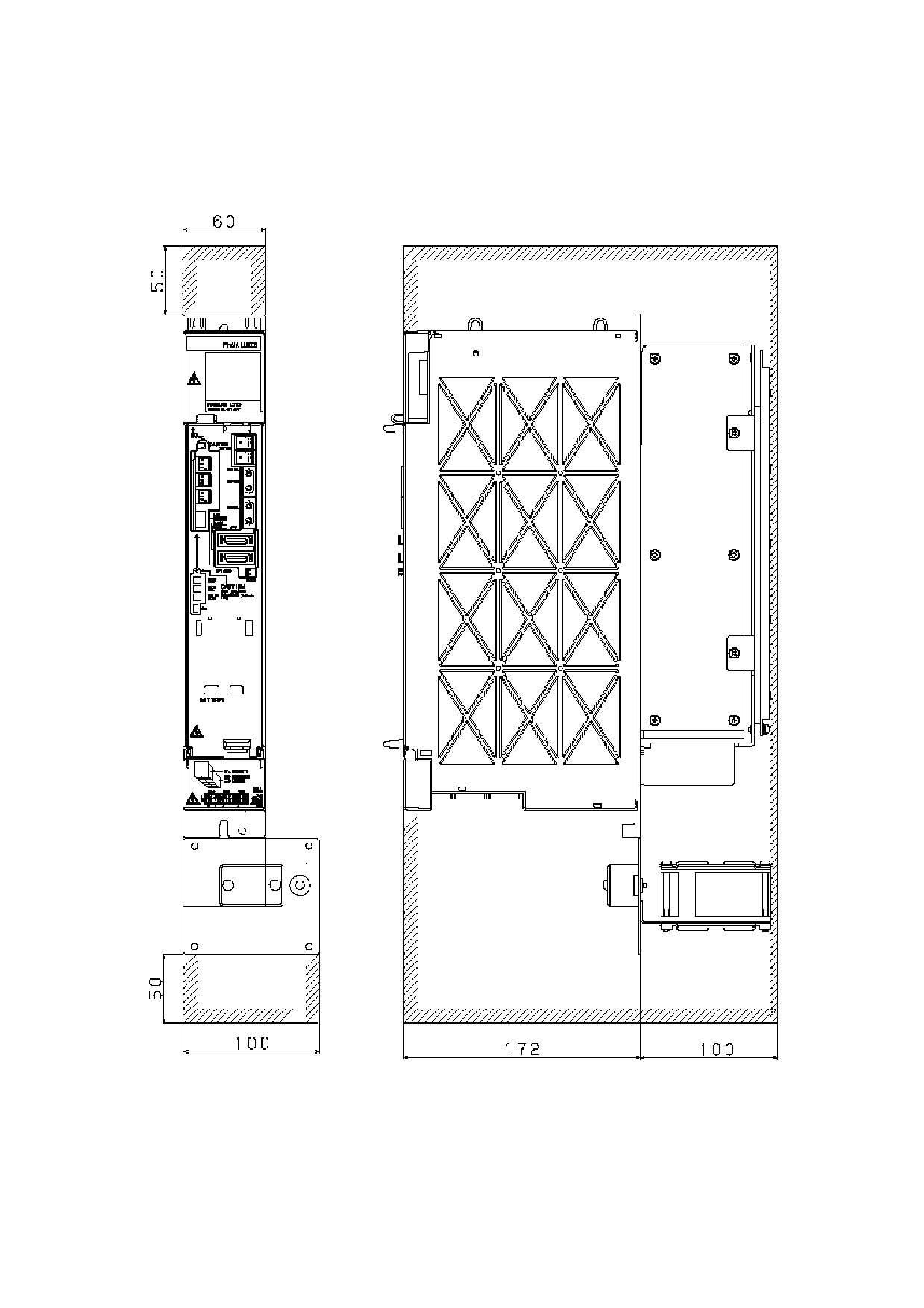
8.3.2
Maintenance Area for the SVM1-40i and SVM1-80i
When no cooling fan AC motor (A06B-6134-K002) is used to cool
the heat sink
- 63 -
8.EXTERNAL DIMENSIONS / PANEL CUT-OUT DRAWINGS / MAINTENANCE AREA SVM B-65322EN/02
When the cooling fan AC motor (A06B-6134-K002) is used to cool
the heat sink
- 64 -
B-65322EN/02
SVM
9.TOTAL CONNECTION DIAGRAM
9
TOTAL CONNECTION DIAGRAM
- 65 -
9.TOTAL CONNECTION DIAGRAM
SVM
B-65322EN/02
9.1
CONNECTION DIAGRAM
9.1.1
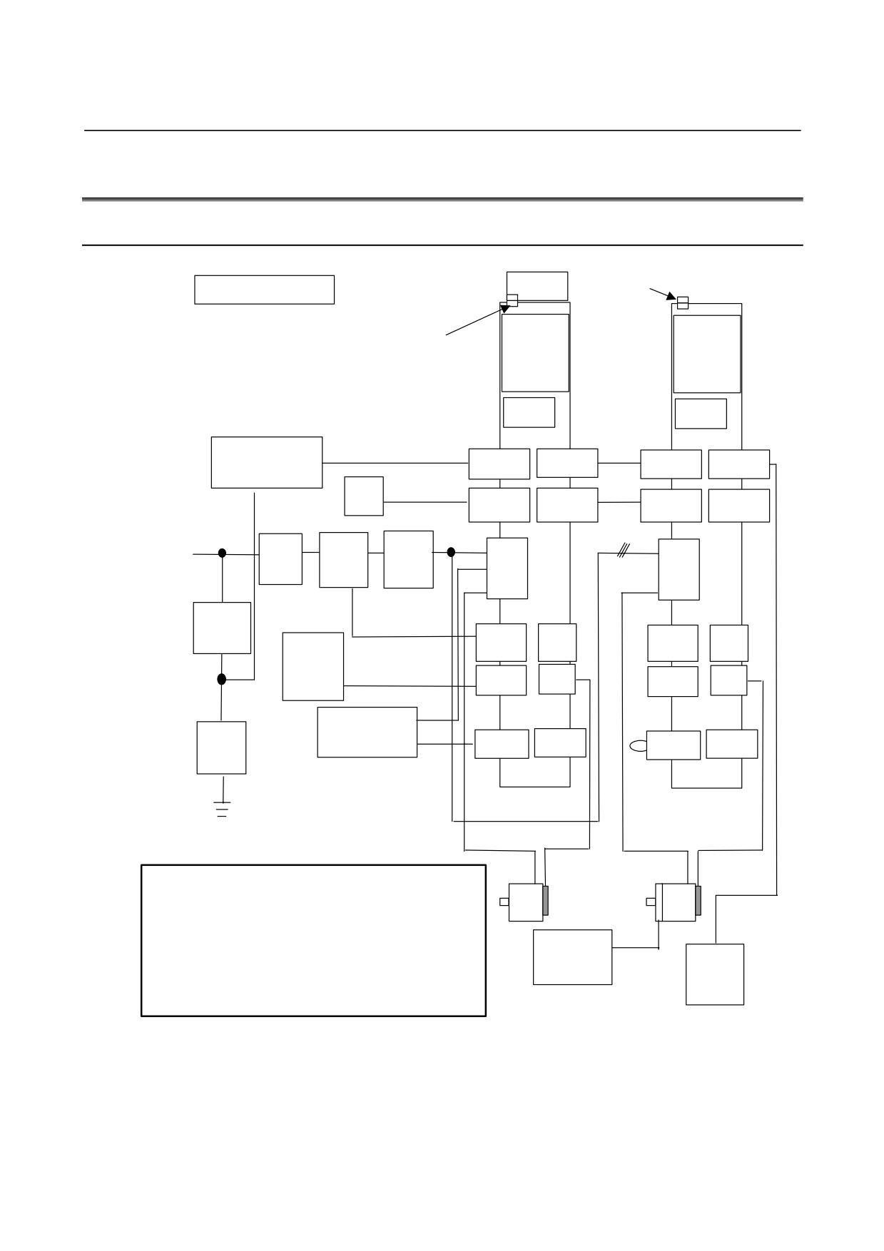
SVM1-4i and SVM1-20i
Dummy connector for fan
Fan unit
4-A type, 20-A type
βi
βi
Connector for
SVM
SVM
fan
20A
4A
FUSE
FUSE
Stabilized
K11
K6
power supply
CXA19B
CXA19A
CXA19B
CXA19A
24 VDC
NC
Optical cable
COP10B
COP10A
COP10B
COP10A
Optical
3-phase : 200 to 240VAC
cable
1-phase : 220 to 240VAC
Circuit
Magnetic
AC
K2
K2
CZ7
CZ7
breaker
contactor
line
K4
filter
5 A
K7
Circuit
breaker
CX29
JX5
CX29
JX5
Emergency
stop switch
K1
K1
K8
CX30
JF1
CX30
JF1
Separated
Lightning
regenerative
CXA20
CX5X
CX5X
surge
discharge resistor
CXA20
absorber
K5
K10
K10
K5
K3
K3
CAUTION
K9
1 Always install the circuit breakers, magnetic contactor, and AC
line filter.
2 Use the stabilized 24VDC power supply for the amplifier.
24VDC power supply for the amplifier and 24VDC power supply
for the motor brake cannot be shared.
24 V power
3 The cabling of CX29 and CX30 of the second and subsequent
supply for
Battery
amplifiers may be omitted. For details, see "TOTAL
motor brake
case
CONNECTION DIAGRAM".
4 Leave JX5 open.
- 66 -
B-65322EN/02
SVM
9.TOTAL CONNECTION DIAGRAM
NOTE
1 Always install the circuit breakers, magnetic
contactor, and AC line filter.
2 To protect the equipment from lightning surge
voltages, install a lightning surge absorber across
each pair of power lines and across each power line
and the grounding line at the power inlet of the
power magnetics cabinet.
WARNING
Defects, such as a loose screw and an incorrectly
inserted connector, can lead to a motor malfunction,
excessive heat generation, and a ground fault.
Exercise adequate care in installing servo
amplifiers.
A loose screw (or, if a connector is used, a loose
connector contact or an incorrect connector
pin-to-cable connection) on high-current carrying
power supply wires or motor power wires can lead
to fire. Exercise adequate care in wiring.
- 67 -
9.TOTAL CONNECTION DIAGRAM
SVM
B-65322EN/02
9.1.2
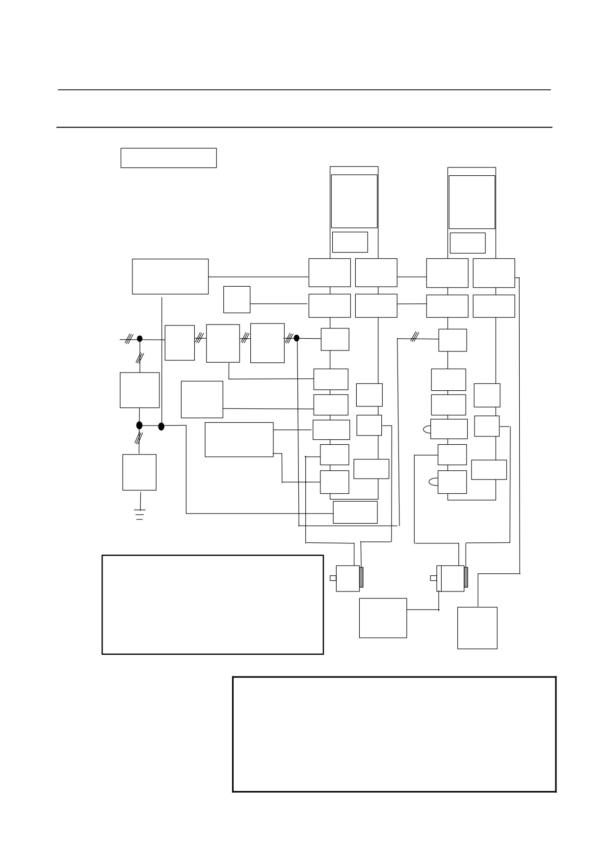
SVM1-40i and SVM1-80i
40-A type, 80-A type
βi
βi
SVM
SVM
80A
40A
FUSE
FUSE
Stabilized
K11
CXA19B
CXA19A
K6
CXA19B
CXA19A
power supply
24 VDC
NC
Optical cable
COP10B
COP10A
COP10B
COP10A
3-phase : 200 to 240VAC
Optical
cable
Circuit
Magnetic
AC
CZ4
CZ4
breaker
contactor
line
filter
K2
K2
K7
CX29
CX29
5 A
Circuit
Emergency
JX5
JX5
breaker
stop switch
K8
CX30
CX30
K5
JF1
JF1
CXA20
K5
CXA20
Separated
regenerative
discharge resistor
CZ5
CZ5
Lightning
K4
CX5X
CX5X
surge
absorber
CZ6
CZ6
K10
K10
K4
Fan unit
K3
K1
K3
K1
K9
CAUTION
1 Always install the circuit breakers, magnetic contactor, and
AC line filter.
2 Use the stabilized 24VDC power supply for the amplifier.
24VDC power supply for the amplifier and 24VDC power
supply for the motor brake cannot be shared.
24 V power
3 The cabling of CX29 and CX30 of the second and
supply for
Battery
subsequent amplifiers may be omitted. For details, see
motor brake
case
"TOTAL CONNECTION DIAGRAM".
4 Leave JX5 open.
NOTE
1 Always install the circuit breakers, magnetic
contactor, and AC line filter.
2 To protect the equipment from lightning surge
voltages, install a lightning surge absorber across
each pair of power lines and across each power line
and the grounding line at the power inlet of the
power magnetics cabinet.
- 68 -
B-65322EN/02
SVM
9.TOTAL CONNECTION DIAGRAM
WARNING
Defects, such as a loose screw and an incorrectly
inserted connector, can lead to a motor malfunction,
excessive heat generation, and a ground fault.
Exercise adequate care in installing servo
amplifiers.
A loose screw (or, if a connector is used, a loose
connector contact or an incorrect connector
pin-to-cable connection) on high-current carrying
power supply wires or motor power wires can lead
to fire. Exercise adequate care in wiring.
- 69 -
9.TOTAL CONNECTION DIAGRAM
SVM
B-65322EN/02
9.2
CONNECTOR LOCATION
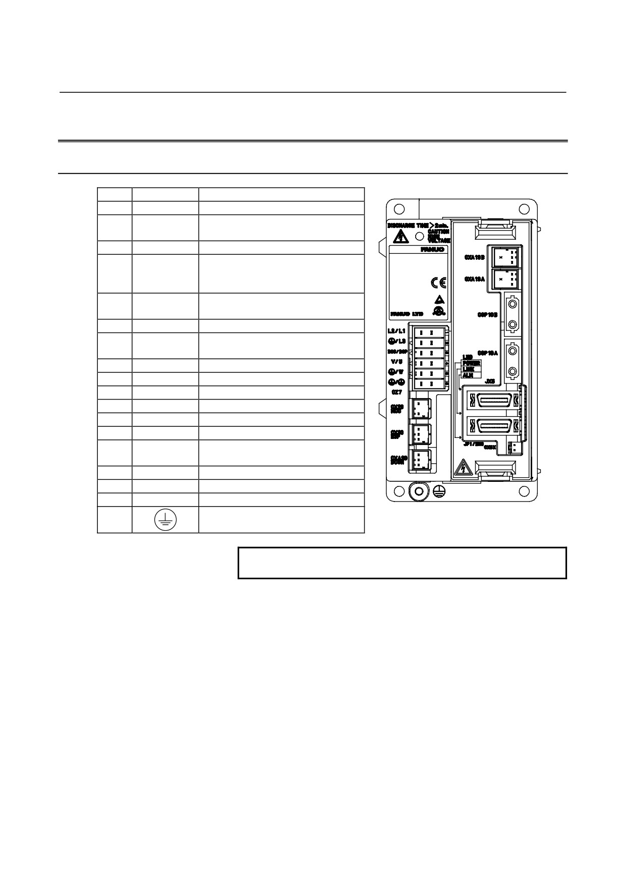
9.2.1
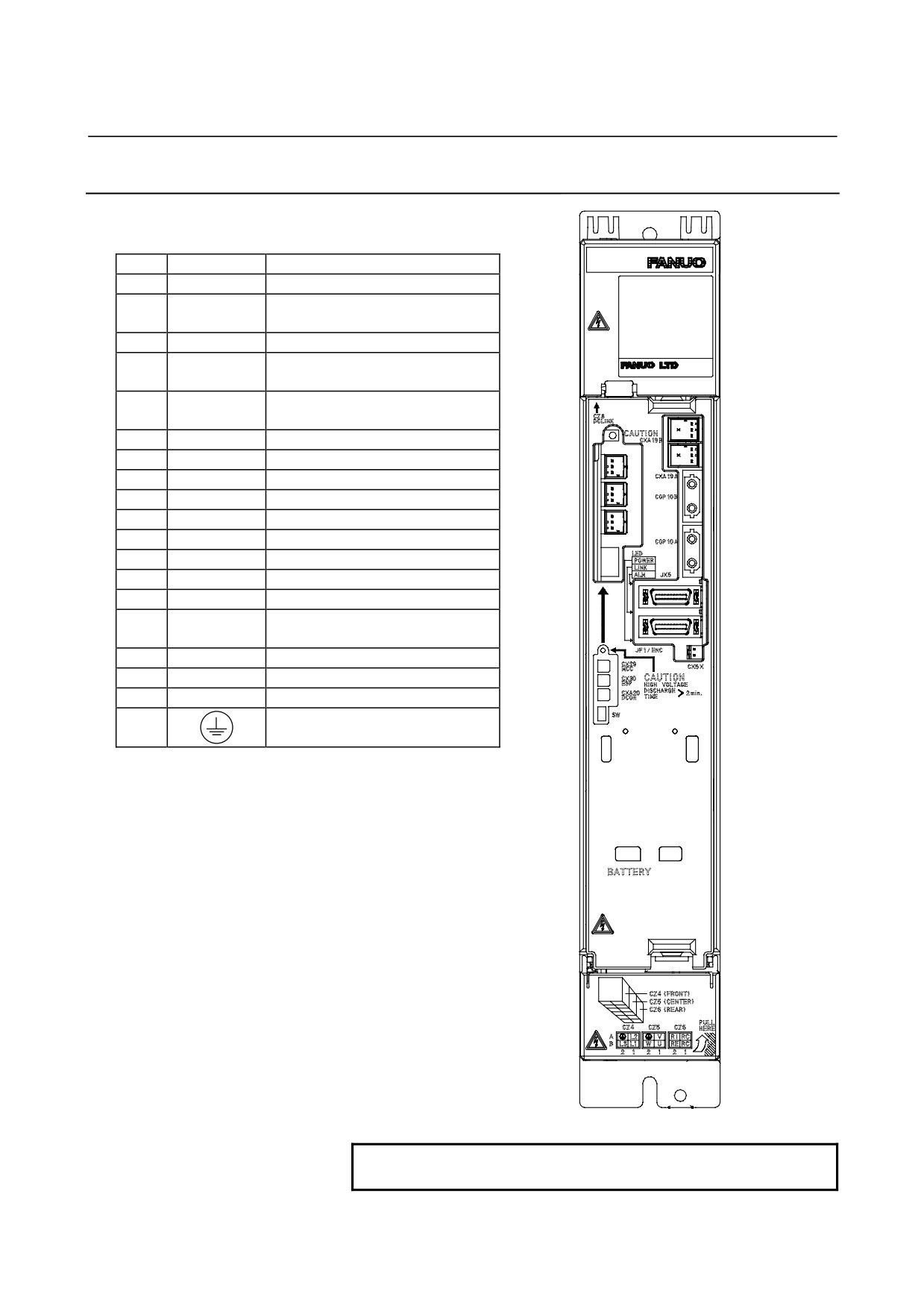
SVM1-4i and SVM1-20i
No.
Name
Remarks
1
DC link charge LED
CZ7-1
(1)
2
Main power input connector
CZ7-2
3
CZ7-3
Discharge register connector
(8)(9)
CZ7-4
4
CZ7-5
Motor power connector
CZ7-6
(10)
Connector for main power MCC
5
CX29
control signal
Yamanashi 401-0597 JAPAN
made in JAPAN
6
CX30
ESP signal connection connector
(2)
Regenerative resistor connector (for
7
CXA20
(11)
alarms)
(3)
8
CXA19B
24VDC power input
(4)
9
CXA19A
24VDC power input
10
COP10B
Servo FSSB I/F
(12)
11
COP10A
Servo FSSB I/F
(5)
(14)(13)
12
ALM
Servo alarm status display LED
13
JX5
Connector for testing(*1)
(6)
(16)(15)
FSSB communication status display
(17)
(7)
14
LINK
LED
15
JF1
Pulsecoder
16
POWER
Control power status display LED
17
CX5X
Absolute Pulsecoder battery
(18)
18
Tapped hole for grounding the flange
NOTE
*1 Connect nothing to JX5, and leave it open.
- 70 -
B-65322EN/02
SVM
9.TOTAL CONNECTION DIAGRAM
9.2.2
SVM1-40i and SVM1-80i
No.
Name
Remarks
1
DC link charge LED
Connector for main power MCC
2
CX29
control signal
3
CX30
ESP signal connection connector
Regenerative resistor connector (for
4
CXA20
(1)
Yamanashi 401-0597 JAPAN
(9)
alarms)
(10)
Setting switch
(2)
5
SW
(DC alarm level)
(3)
6
CZ4
Main power input connector
(11)
7
CZ5
Motor power connector
(4)
8
CZ6
Discharge register connector
(12)
9
CXA19B
24VDC power input
(5)
10
CXA19A
24VDC power input
(13)
11
COP10B
Servo FSSB I/F
(14)
(15)
12
COP10A
Servo FSSB I/F
(16)
13
ALM
Servo alarm status display LED
(17)
14
JX5
Connector for testing(*1)
(18)
FSSB communication status display
15
LINK
LED
16
JF1
Pulsecoder
17
POWER
Control power status display LED
18
CX5X
Absolute Pulsecoder battery
19
Tapped hole for grounding the flange
(6), (7), (8)
(19)
NOTE
*1 Connect nothing to JX5, and leave it open.
- 71 -
9.TOTAL CONNECTION DIAGRAM
SVM
B-65322EN/02
9.2.3
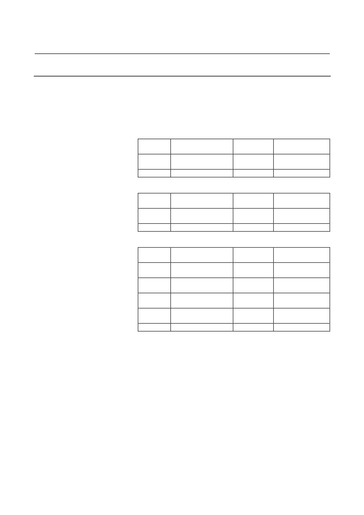
Connection Tools
The ordering specification drawing numbers of connection tools for
connectors when the tools are purchased from FANUC are listed
below. You may also purchase these tools directly from the
manufacturer.
Connectors manufactured by Tyco Electronics AMP
D-2000 series
Ordering specification
Manufacturer
Type
Use
drawing No.
part No.
M size
Option
A06B-6110-K220#D2M
91595-1
Contact crimping tool
Option
A06B-6110-K220#D2R
1276716-1
Contact extractor
D-3000 series
Ordering specification
Manufacturer
Type
Use
drawing No.
part No.
L size
Option
A06B-6110-K220#D3L
91558-1
Contact crimping tool
Option
A06B-6110-K220#D3R
234168-1
Contact extractor
D-5000 series
Ordering specification
Manufacturer
Type
Use
drawing No.
part No.
SS size
Option
A06B-6110-K220#D5SS
91596-1
Contact crimping tool
S size
Option
A06B-6110-K220#D5S
234170-1
Contact crimping tool
M size
Option
A06B-6110-K220#D5M
234171-1
Contact crimping tool
L size
Option
A06B-6110-K220#D5L
1366044-1
Contact crimping tool
Option
A06B-6110-K220#D5R
409158-1
Contact extractor
- 72 -
B-65322EN/02
SVM
9.TOTAL CONNECTION DIAGRAM
9.2.4
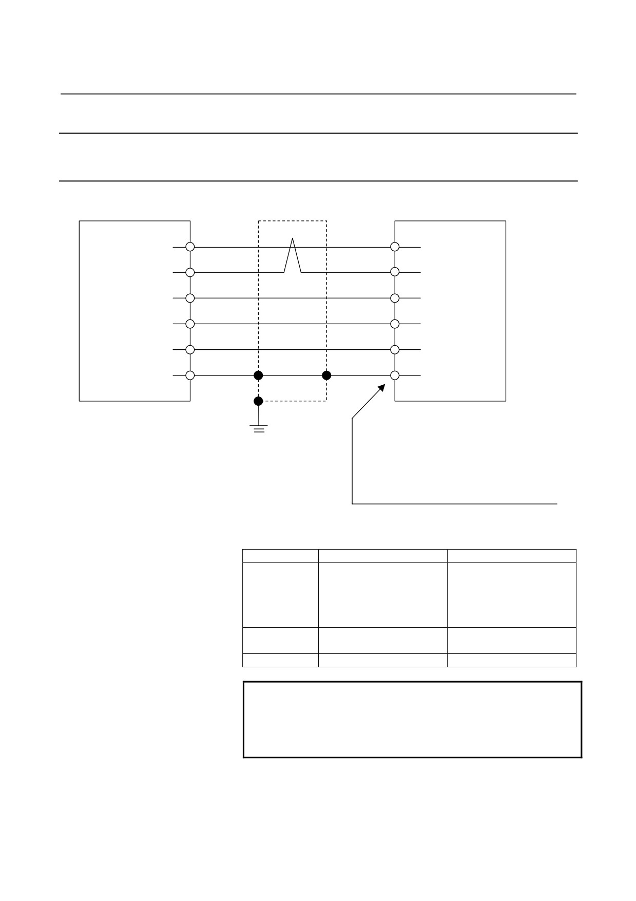
Details of Cable K1
9.2.4.1 Servo motor αi, αis series, Servo motor βis series (β0.4/5000is
to β22/2000is)
Shield
SVM
Servo motor
(5)
RD
(6)
(6)
*RD
(5)
(9, 20)
5V
(8, 9)
(12, 14)
0V
(7, 10)
(7)
6V
(4)
Drain wire
(16)
FG
(3)
20-pin half-pitch connector
Grounding
Connector (Japan Aviation Electronics Industry)
plate
JN2x S10SL1 : for φ5.7 to 7.3 sheath diameter
JN2x S10SL2 : for φ6.5 to 8.0 sheath diameter
D : Straight plug
F : Angle plug
Contact (Japan Aviation Electronics Industry)
JN1-22-22S
Using cable conductor
Cable length
28 m or less
50 m or less
0.3mm2 × 5
0.5mm2 × 5
Wire construction
Wire construction
5V, 0V,6V
12/0.18 or 60/0.08
20/0.18 or 104/0.08
Insulation outer diameter
Insulation outer diameter
φ1.5 or less
φ1.5 or less
0.18mm2 or more
0.18mm2 or more
RD, *RD
Twisted-pair wire
Twisted-pair wire
Drain wire
0.15mm2 or more
0.15mm2 or more
NOTE
The ground plate to which the shield is connected
must be placed as close as possible to the servo
amplifier so that distance between the ground plate
and the servo amplifier becomes shortest.
* This applies also to the αMi and αCi series servo motors.
- 73 -