FANUC AC Servo Amplifiers βi Series. Description Manual (B-65322EN/02) - page 2
3.SPECIFICATIONS
SVM
B-65322EN/02
3.5
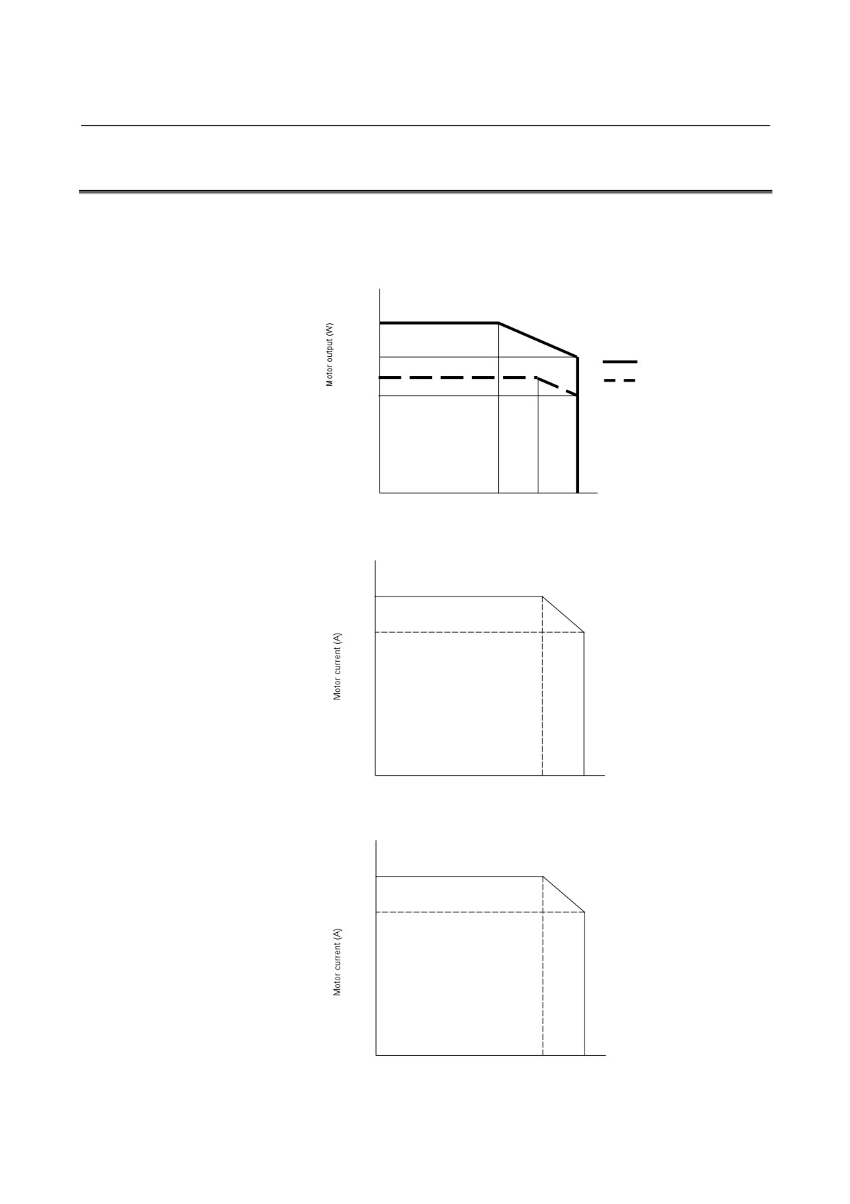
DERATING
Consider derating as shown below, according to ambient
temperatures.
SVM1-20i
Output derating for single-phase input
1200
900
With fan
750
Without fan
500
0
0
35
45
55
Temperature (°C)
SVM1-40i
Output derating for 3-phase input
13.0
9.8
0
0
45
55
Temperature (°C)
SVM1-80i
Output derating for 3-phase input
18.5
15.0
0
0
45
55
Temperature (°C)
- 12 -
B-65322EN/02
SVM
3.SPECIFICATIONS
3.6
SEPARATED REGENERATIVE DISCHARGE RESISTOR
3.6.1
When No Separated Regenerative Discharge Resistor Is
Needed
No separated regenerative discharge resistor is needed if the energy
regenerated per regeneration cycle is not higher than the amount [J] of
energy listed below.
Note in mind that an incorrect connection can damage the
amplifier.
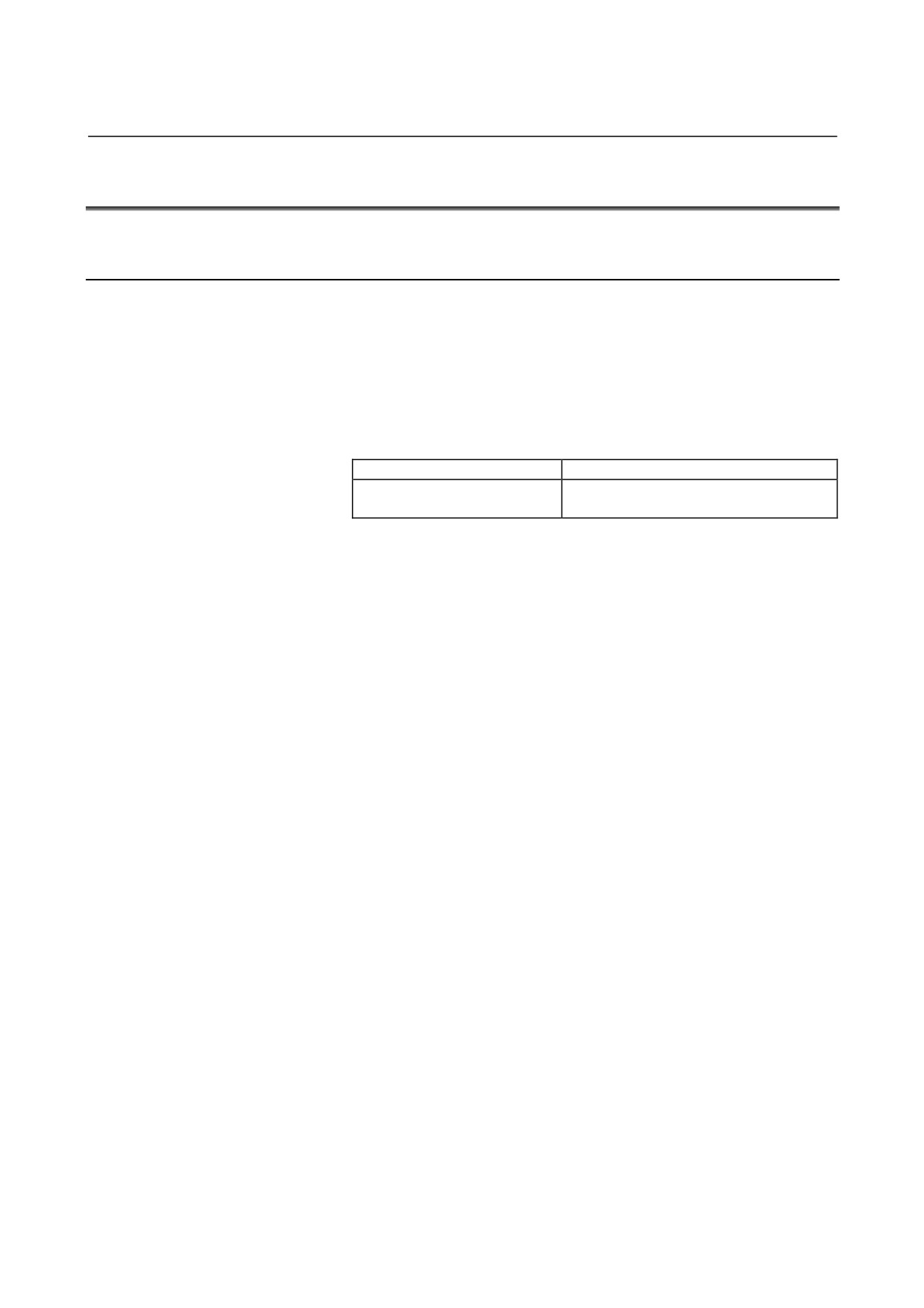
Table 3.6.1 Maximum regenerative energy amount permitted for
individual amplifier models
Amplifier model
Permissible regenerative energy amount
SVM-4i
16 [J]
SVM-20i
How to calculate the amount of energy regenerated per regeneration cycle
- For horizontal movement
(a) SI unit system
−3
2
−2
P=
(5.48×10
⋅ (Jm + JL) ⋅Vm
−5.23×10
⋅ ta ⋅Vm ⋅
TL)[J]
(Expression1)
Jm: Rotor inertia of the motor [kg⋅m2]
JL: Motor-shaft-converted inertia of the load [kg⋅m2]
Vm: Motor speed at rapid traverse [min-1]
ta: Rapid traverse acceleration/deceleration time [sec]
TL: Machine frictional torque (motor-converted value) [N⋅m]
(b) CGS unit system
−4
2
−3
P=
(5.37×10
⋅ (Jm + JL) ⋅Vm
−5.13×10
⋅ ta ⋅Vm ⋅
TL)[J]
(Expression 1)
Jm: Rotor inertia of the motor [kgf⋅cm⋅sec2]
JL: Motor-shaft-converted inertia of the load [kgf⋅cm⋅sec2]
Vm: Motor speed at rapid traverse [min-1]
ta: Rapid traverse acceleration/deceleration time [sec]
TL: Machine frictional torque (motor-converted value) [kg⋅cm]
- 13 -
3.SPECIFICATIONS
SVM
B-65322EN/02
- For vertical movement
(a) SI unit system
−1
Q=1.047×10
⋅ Th ⋅Vm ⋅
ta
[J]
(Expression 2)
Th: Upward torque that the motor applies at the time of
downward rapid traverse [N⋅m]
Vm: Motor speed at rapid traverse [min-1]
ta : Rapid traverse acceleration/deceleration time [sec]
(b) CGS unit system
−2
Q=1.026×10
⋅ Th ⋅Vm ⋅
ta
[J]
(Expression 2)
Th: Upward torque that the motor applies at the time of
downward rapid traverse [kg⋅cm]
Vm: Motor speed at rapid traverse [min-1]
ta : Rapid traverse acceleration/deceleration time [sec]
If the motor load moves up and down, the sum of expressions 1 and 2
gives the amount of energy regenerated per regeneration cycle.
R = P + Q
[J]
(Expression 3)
- 14 -
B-65322EN/02
SVM
3.SPECIFICATIONS
3.6.2
When a Separated Regenerative Discharge Resistor Is
Needed
If the amount of energy regenerated per regeneration cycle exceeds
the maximum amount of energy that a servo amplifier can handle, a
DC link overvoltage alarm occurs. In this case, a separated
regenerative discharge resistor is needed.
Note in mind that an incorrect connection can damage the
amplifier.
Selecting a regenerative discharge resistor
First obtain how much regenerative energy occurs.
- For horizontal movement
Servo motor (for horizontal movement)
Amount of regenerative discharge (power [W]) when rapid traverse
acceleration/deceleration is performed once every F sec
(a) SI unit system
1
−2
−3
2
w1
=
×
(5.48×10
⋅
(Jm + JL)
⋅
Vm
−
5.23×10
⋅
ta ⋅Vm
⋅
TL)[W]
(Expression 4)
F
F : Frequency of rapid traverse acceleration/deceleration
[sec/number of times]
Unless
otherwise
specified,
rapid
traverse
acceleration/deceleration is assumed to be performed about
once every 5 seconds.
Jm: Rotor inertia of the motor [kg⋅m2]
JL: Motor-shaft-converted inertia of the load [kg⋅m2]
Vm: Motor speed at rapid traverse [min-1]
ta: Rapid traverse acceleration/deceleration time [sec]
TL: Machine frictional torque (motor-converted value) [N⋅m]
(b) CGS unit system
1
−4
2
−3
w1
=
×
(5.37
×10
⋅
(Jm + JL)
⋅
Vm
−
5.13×10
⋅
ta ⋅Vm
⋅
TL)[W]
(Expression 4)
F
F : Frequency of rapid traverse acceleration/deceleration
[sec/number of times]
Unless
otherwise
specified,
rapid
traverse
acceleration/deceleration is assumed to be performed about
once every 5 seconds.
Jm: Rotor inertia of the motor [kgf⋅cm⋅sec2]
JL: Motor-shaft-converted inertia of the load [kgf⋅cm⋅sec2]
Vm: Motor speed at rapid traverse [min-1]
ta: Rapid traverse acceleration/deceleration time [sec]
TL: Machine frictional torque (motor-converted value) [kg⋅cm]
From Table 3.6.2, select a separated regenerative discharge unit
having a greater regenerative discharge capacity than the value
obtained from (Expression 4).
- 15 -
3.SPECIFICATIONS
SVM
B-65322EN/02
- For vertical movement
The amount of regenerative discharge (power [W]) when the operation
duty for downward rapid traverse is D(%)
(a) SI unit system
D
w2
=
1.047
×10−1
⋅ Th ⋅ Vm ×
[W
]
(Expression 5)
100
Th: Upward torque that the motor applies at the time of
downward rapid traverse [N⋅m]
Vm: Motor speed at rapid traverse [min-1]
D : Operation duty [%] for downward rapid traverse
D is set to 50% maximum. Usually, D is less than 50%.
(b) CGS unit system
D
w2
=
1.026
×10−2
⋅ Th ⋅ Vm ×
[W
]
(Expression 5)
100
Th: Upward torque that the motor applies at the time of
downward rapid traverse [kg⋅cm]
Vm: Motor speed at rapid traverse [min-1]
D : Operation duty [%] for downward rapid traverse
D is set to 50% maximum. Usually, D is less than 50%.
If the motor load moves up and down, the sum of expressions 4 and 5
gives the amount of energy regenerated per regeneration cycle.
w = w1 + w2 [W]
(Expression 6)
From Table 3.6.2, select a separated regenerative discharge resistor
whose regenerative discharge capacity is larger than the regenerative
energy obtained in expression 6.
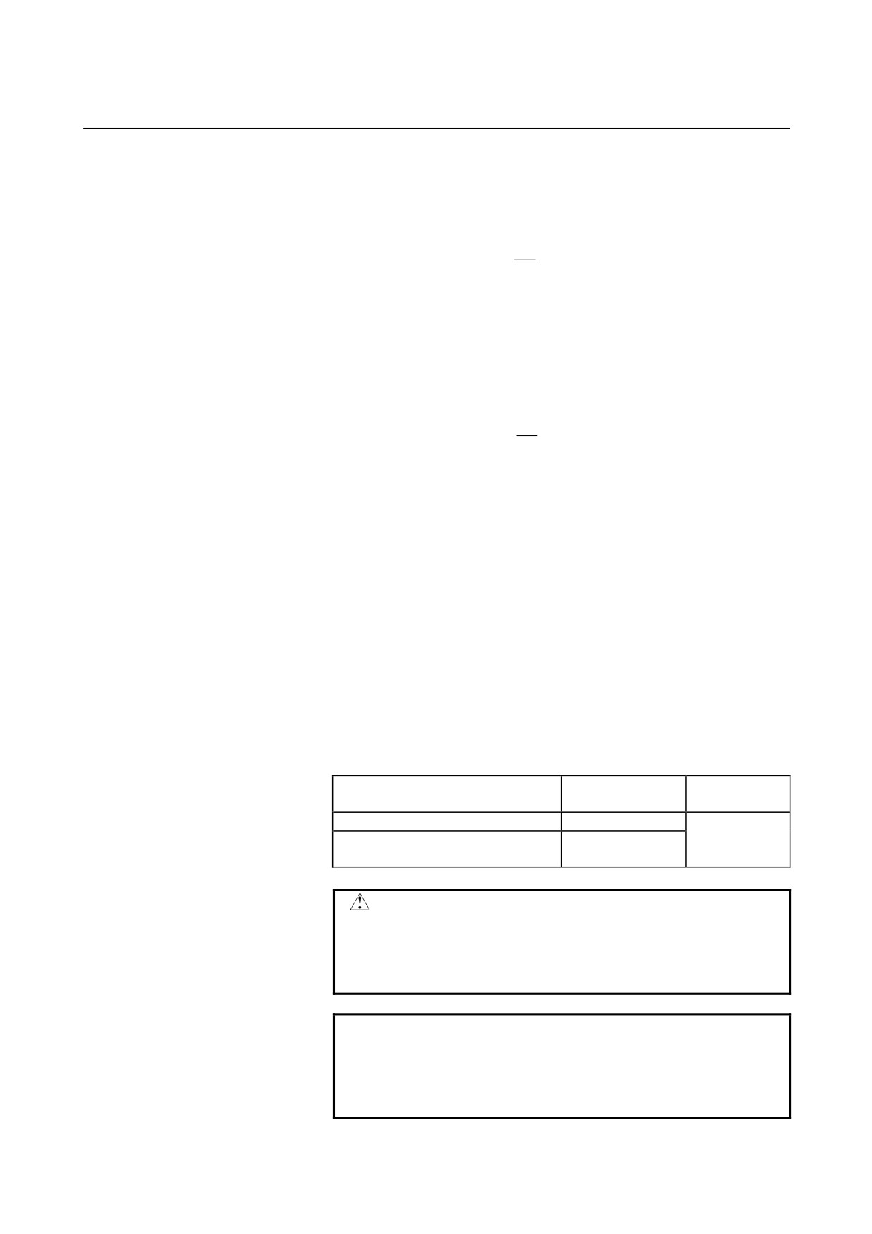
Table 3.6.2 Regenerative discharge capacity of separated regenerative
discharge resistors
Separated regenerative discharge
Regenerative
Condition
resistor
discharge capacity
A06B-6130-H401 (30 Ω)
20 W
Wind speed
(Caution)
100 W
of 0 m/s
A06B-6130-H402 (30 Ω)
CAUTION
Do not use a regenerative resistor cable longer
than 1 m. Otherwise, it is likely that the
regenerative circuit in the amplifier may
malfunction or the amplifier may be damaged.
NOTE
If the permissible value of a separated
regenerative discharge resistor is exceeded during
use, the unit overheats, resulting in the built-in
thermostat operating to issue an overheat alarm.
- 16 -
B-65322EN/02
SVM
3.SPECIFICATIONS
3.6.3
When Amplifier Models SVM-40i and SVM-80i Are Used
If the amount of regenerative discharge from a servo motor exceeds
the regenerative discharge capacity of the regenerative discharge
resistor incorporated in the corresponding servo amplifier, a separated
regenerative discharge resistor is needed.
If the motor regenerative discharge amount R obtained in Subsection
3.6.2 exceeds the corresponding value listed in Table
3.6.3
(a),
“Regenerative discharge capacity of the regenerative discharge
resistor incorporated in servo amplifiers,” use a separated regenerative
discharge resistor.
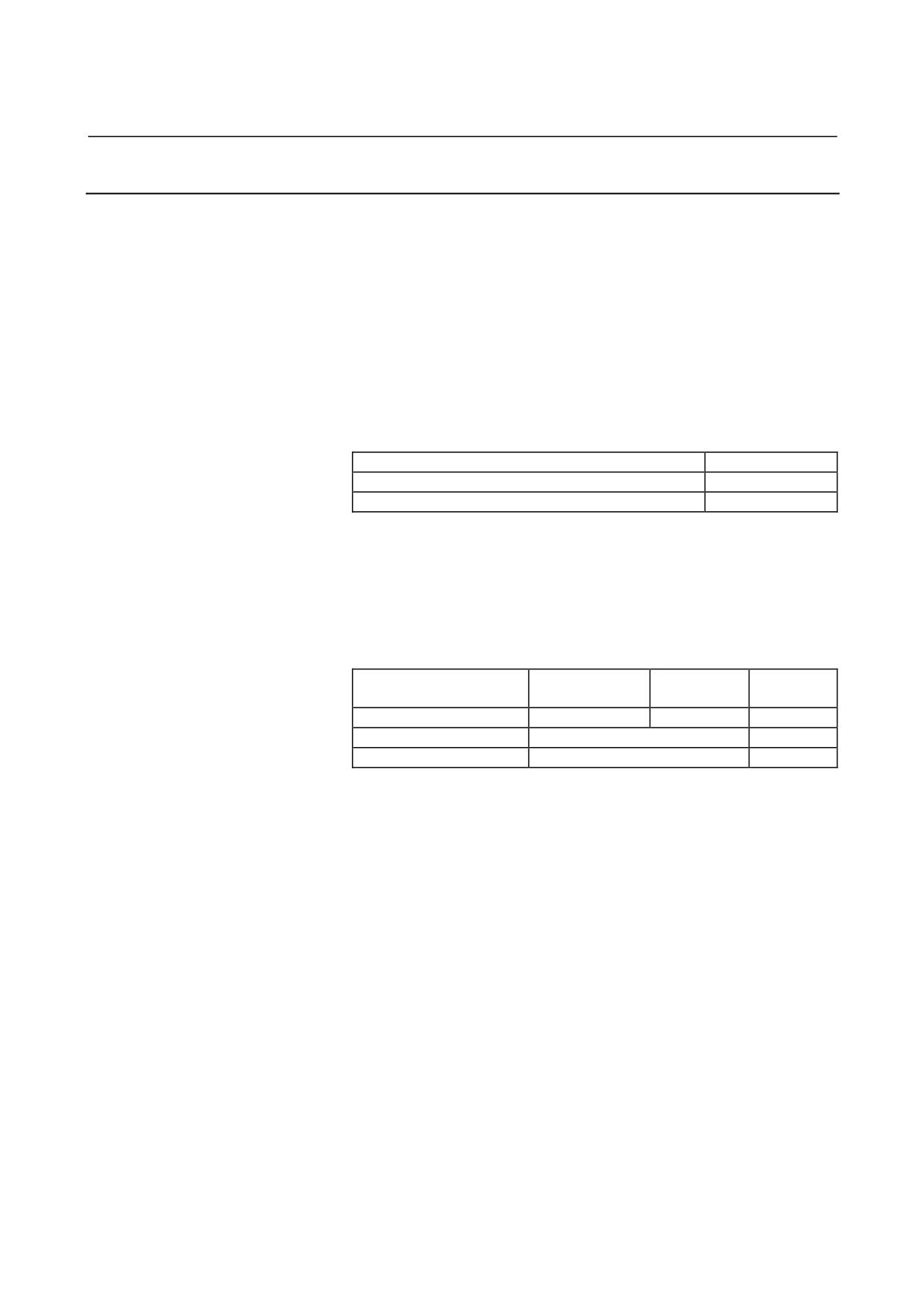
Table 3.6.3 (a) Regenerative discharge capacity of the regenerative
discharge resistor incorporated in servo amplifiers
Servo amplifier
Capacity
A06B-6130-H003
50 W
A06B-6130-H004
130 W
The following table lists the separated regenerative discharge resistors
that are available.
Select a separated regenerative discharge resistor whose discharge
capacity satisfies your requirement.
Table 3.6.3(b) Regenerative discharge capacity of regenerative
discharge resistors installed separately from servo amplifiers
Separated regenerative
Wind speed of 0
Wind speed
Wind speed
discharge resistor
m/s
of 2 m/s
of 4 m/s
A06B-6089-H500
R = 200W
R = 400 W
R = 600 W
A06B-6089-H713
Incorporates a cooling fan motor.
R = 800 W
A06B-6089-H714
Incorporates a cooling fan motor.
R = 1200 W
- 17 -
3.SPECIFICATIONS
SVM
B-65322EN/02
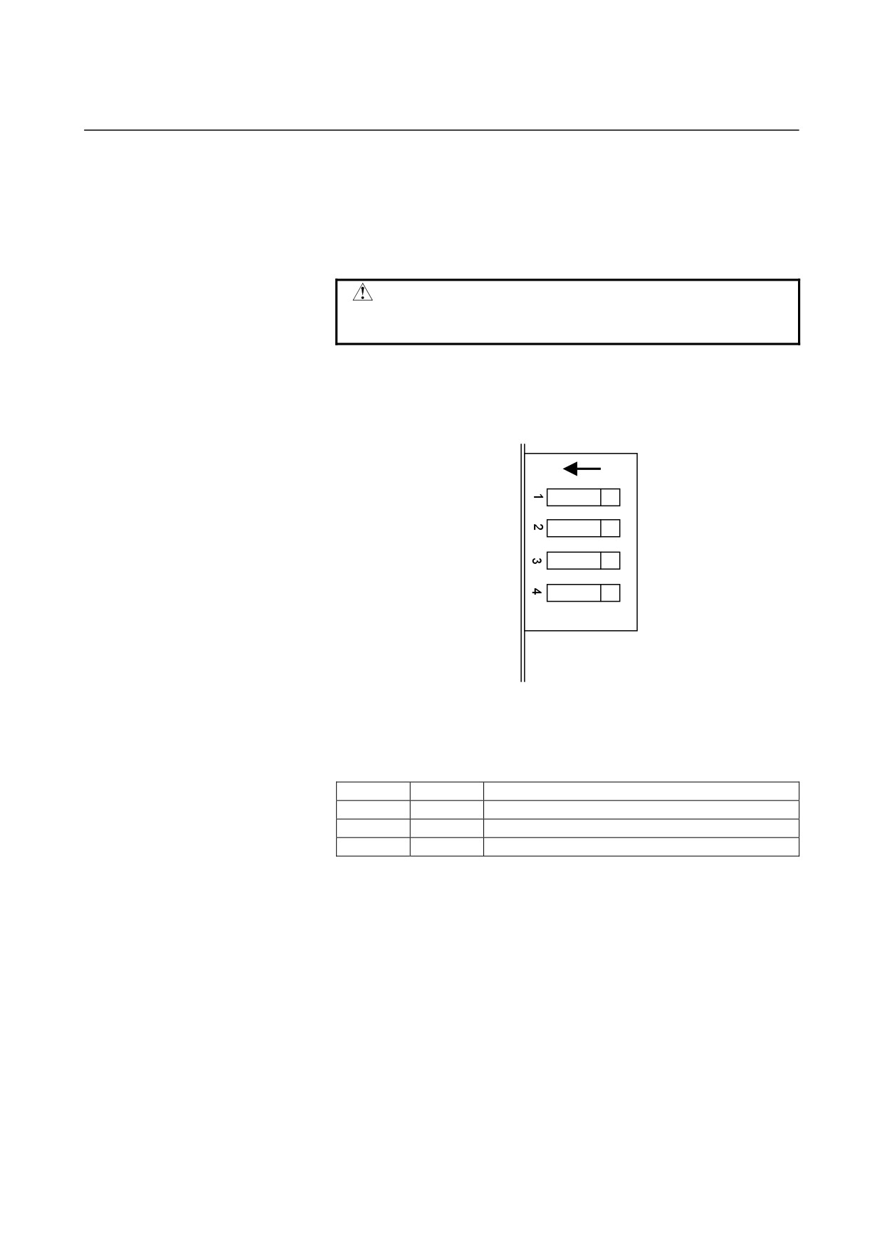
Set-up switch (for changing the DC alarm level)
Switch setting (for the SVM1-40i and SVM1-80i)
The SVM1-40i and SVM1-80i each have four switches on their front
panel for protecting regenerative resistors. Be sure to set these
switches to the positions that match the resistors used.
CAUTION
An incorrect switch setting may damage the
regenerative resistor.
These switches are numbered 1 to 4. The one on top is No. 1, the
one below it is No. 2, and so on. When the lever of a switch is at the
left, the switch is on. When it is at the right, the switch is off.
ON
(1) Setting of switches 3 and 4
The setting of switches
3 and 4 varies depending on what
regenerative discharge resistor is used.
⇒ If a switch is incorrectly set up, it is impossible to detect a
regenerative overheat alarm normally.
Switch 3
Switch 4
Regenerative discharge resistor
ON
ON
Incorporated in the amplifier
OFF
ON
Separate unit A06B-6089-H500
OFF
OFF
Separate unit A06B-6089-H713, A06B-6089-H714
(2) Setting of switches 1 and 2
Neither switch 1 nor 2 is used. Leave them off.
- 18 -
B-65322EN/02
SVM
3.SPECIFICATIONS
Cautions for selecting a regenerative discharge resistor
WARNING
1 Regenerative discharge resistors may become
very hot (100 to 200 °C). Be careful not to touch
them.
2 Before touching a regenerative discharge resistor,
for example, for maintenance purposes, turn off all
power to the amplifier, wait for at least 30 minutes,
and make sure that the DC link charge indicator
LED (CAUTION CHARGE) is off and the
regenerative resistor is sufficiently cold.
3 When mounting a regenerative resistor, keep it
sufficiently far from any flammable.
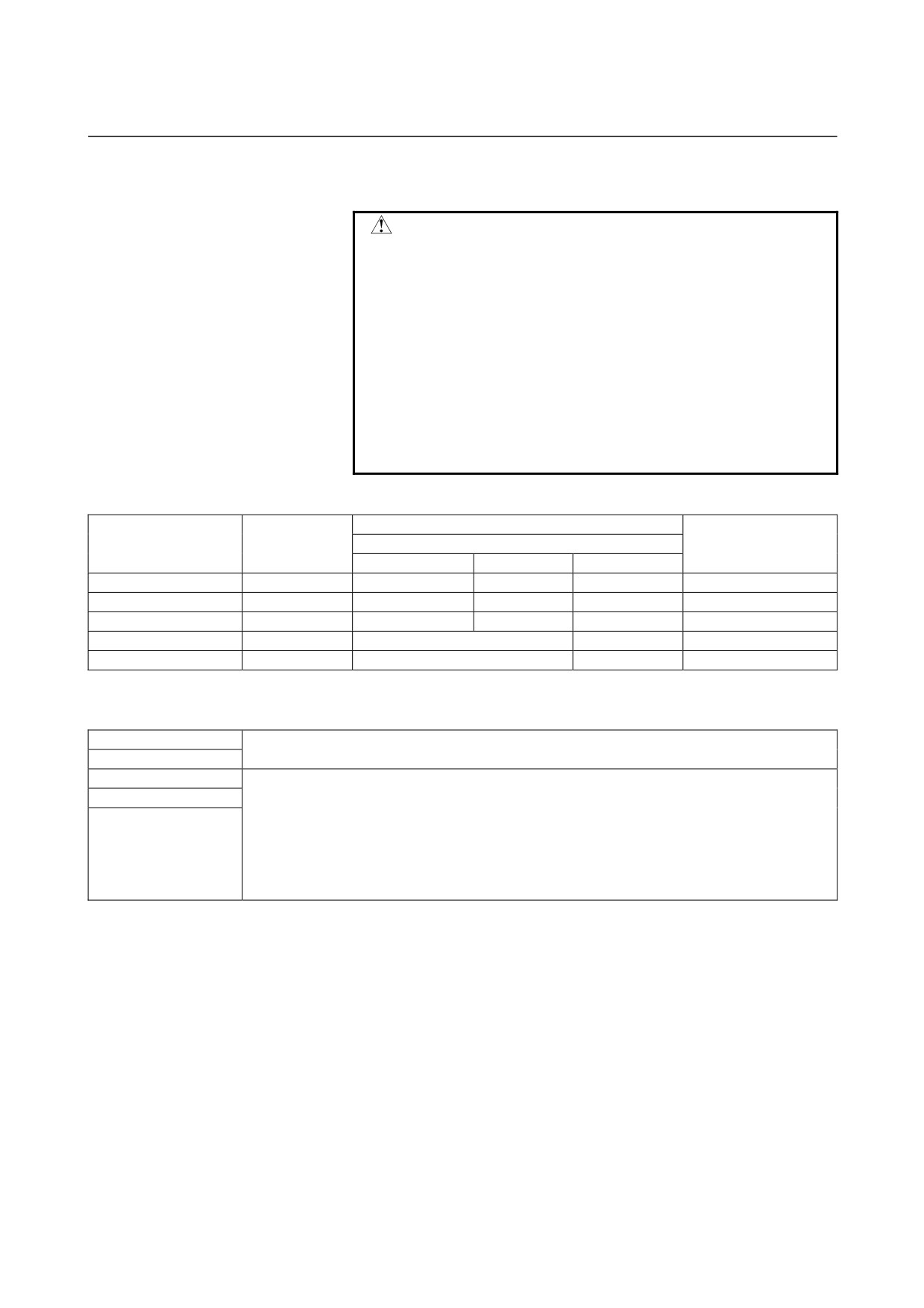
(1) Related ordering numbers
Ordering number of
Capacity
regenerative
Resistance
Wind speed
Remarks
discharge resistor
0 m/s
2 m/s
4 m/s
A06B-6130-H401
30 Ω
20 W
-
-
For 4/20 A
A06B-6130-H402
30 Ω
100 W
-
-
For 4/20 A
A06B-6089-H500
16 Ω
200 W
400 W
600 W
For 40/80 A
A06B-6089-H713
16 Ω
Incorporates a cooling fan motor.
800 W
For 40/80 A
A06B-6089-H714
16 Ω
Incorporates a cooling fan motor.
1200 W
For 40/80 A
(2) Mounting requirements
(a) Cautions in mounting
A06B-6130-H401
Install these models in a completely sealed cabinet.
A06B-6130-H402
A06B-6089-H500
Place the pin side and resistor side (heat generating section) of these models, respectively, in
A06B-6089-H713
a completely sealed cabinet and an exhaust air duct.
(a) Use accompanying gaskets.
(b) Make arrangements so that the pin side and resistor side (heat generating section) can
A06B-6089-H714
be kept from coolant, oil mist, and cuttings.
(c) When taking in fresh air to the resistor (heat generating section), use an air filter at the air
inlet. Also seal the cable inlets, cable outlets and doors securely.
(b) Ambient temperature
0 to 55 °C (at operation)
-20 to 60 °C (at keeping and transportation)
(c) Humidity
Normally 90 % RH or below, and condensation-free
(d) Vibration
In operation : Below 0.5 G
(e) Mounting direction:
Mount the unit securely while referring to the mounting
diagram given below.
- 19 -
3.SPECIFICATIONS
SVM
B-65322EN/02
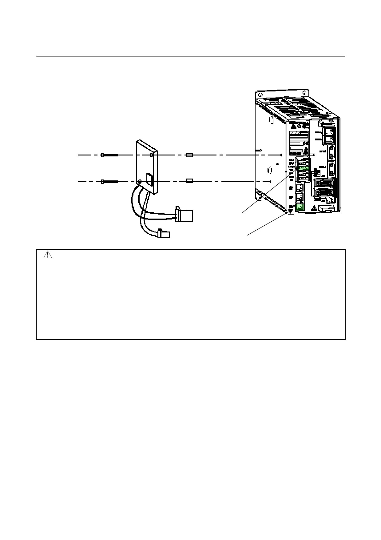
Installation and connection of A06B-6130-H401
To connector CZ7
To connector CXA20
WARNING
1 Regenerative discharge resistors may become very hot (100 to 200 °C). Be
careful not to touch them.
2 Before touching a regenerative discharge resistor, for example, for maintenance
purposes, turn off all power to the amplifier, wait for at least 30 minutes, and make
sure that the DC link charge indicator LED (CAUTION CHARGE) is off and the
regenerative resistor is sufficiently cold.
3 When mounting a regenerative resistor, keep it sufficiently far from any flammable.
4 The minimum clearance between the regenerative resistor and the wall should be
10 mm.
- 20 -
B-65322EN/02
SVM
3.SPECIFICATIONS
Installation and connection of A06B-6130-H402
Front
Side A
Side B
Installation direction
Up
* Spacer
Wall
A B C D
A, D: To connector CZ7
Yamanas hi 401-05 97 JAPAN
made in JAPAN
B, C: To connector CXA20
WARNING
1 Regenerative discharge resistors may become very hot (100 to 200 °C). Be
careful not to touch them.
2 Before touching a regenerative discharge resistor, for example, maintenance
purposes, turn off all power to the amplifier, wait for at least 30 minutes, and
make sure that the DC link charge indicator LED (CAUTION CHARGE) is off
and the regenerative discharge resistor has been cooled down enough.
3 When mounting a regenerative resistor, keep it sufficiently far from any
flammable.
4 The minimum clearance between the regenerative resistor and the wall should
be 10 mm.
- 21 -
4.ORDERING INFORMATION
SVM
B-65322EN/02
4
ORDERING INFORMATION
Refer to the order list (B-65321EN).
- 22 -
B-65322EN/02
SVM
5.POWER SUPPLY
5
POWER SUPPLY
- 23 -
5.POWER SUPPLY
SVM
B-65322EN/02
5.1
INPUT POWER SUPPLY
5.1.1
Three-phase Input Power Supply for Motor Power
-
Nominal rated voltage: 200 to 240 VAC
-
Allowable voltage fluctuation: -15% to +10%
-
Frequency: 50/60 Hz
-
Allowable frequency fluctuation: ±2 Hz
-
Power supply impedance: Voltage fluctuation cased by load (at
maximum output) not to exceed 7%
-
Power supply unbalance: Within ±5% of the rated voltage
NOTE
The allowable voltage fluctuation is a change
observed for several minutes. It is not a continuous
change.
5.1.2
Single-phase Input Power Supply for Motor Power
In European countries, power sources are
380 to 415 VAC and
neutral-grounded. To use the βi series amplifiers in these European
countries, it is necessary to install a power transformer at the input or
supply single-phase power.
To use the motors with single-phase power, observe the following:
Only the SVM1-20i and lower models can support single-phase input.
The other models use the three-phase input power supply
specifications only.
(1) Power supply specification
-
Nominal voltage rating: 220 to 240 VAC
-
Allowable voltage fluctuation: -15% to +10%
-
Frequency: 50/60 Hz
-
Allowable frequency fluctuation: ±2 Hz
-
Voltage fluctuation at acceleration/deceleration: 7% or less
NOTE
The allowable voltage fluctuation is a change
observed for several minutes. It is not a continuous
change.
5.1.3
Single-phase Input for Control Power
Be sure to use a stabilized power supply as the 24-V power supply for
amplifiers. The
24-V power supply for motor brakes cannot be
shared.
-
Nominal rated voltage: 24VDC
-
Allowable voltage fluctuation:
±10%
(including momentary
variations)
-
Power supply ratings
- 24 -

B-65322EN/02
SVM
5.POWER SUPPLY
Power supply rating per amplifier
FSSB interface
0.9A
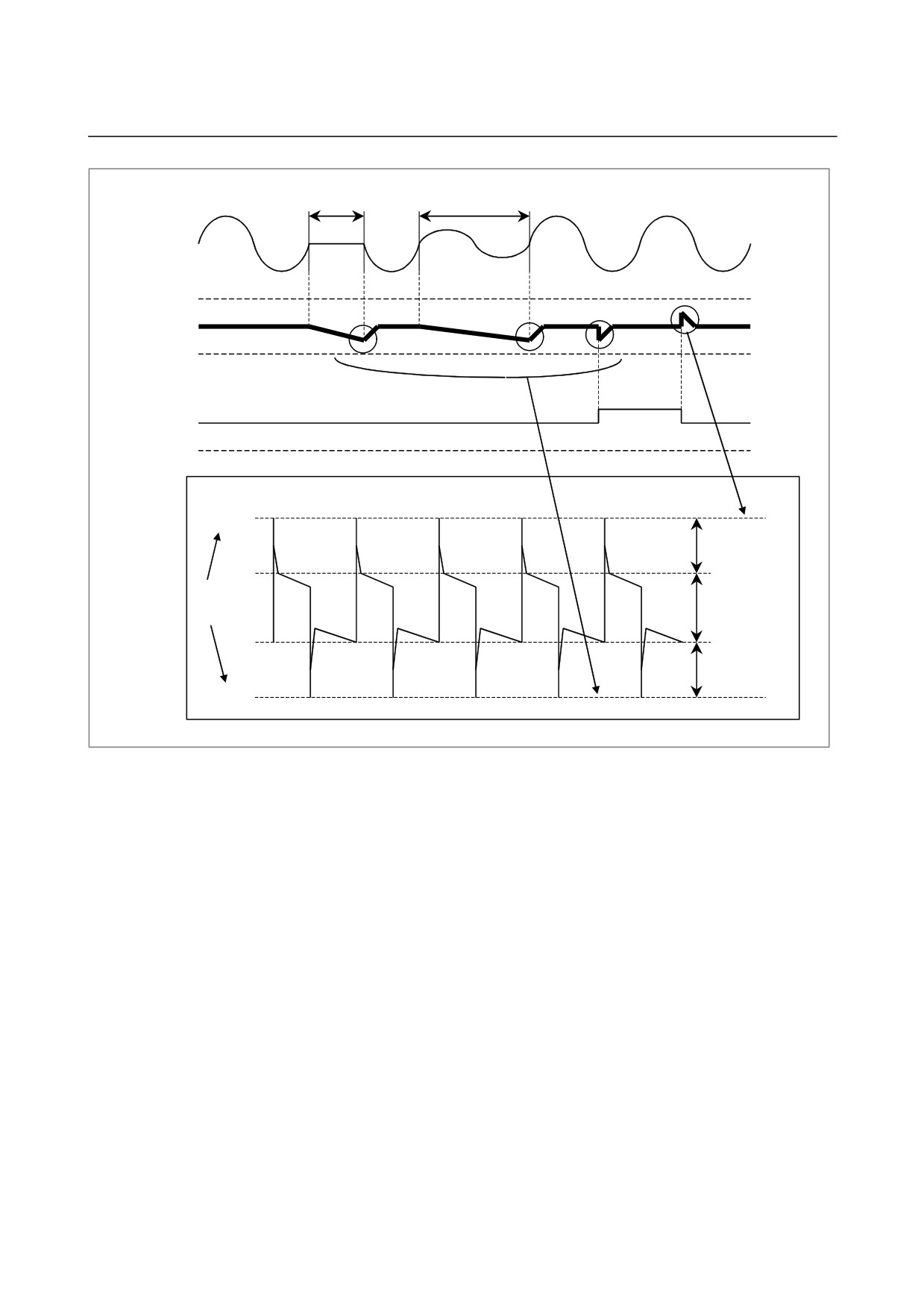
- External 24-VDC power supply specifications
Recommended external
24-VDC power supply
(stabilized power
supply) specifications
(UL1950 must be
satisfied.)
Output voltage
+24V ±10% (21.6V to 26.4V)
(Including ripple voltage and noise. See
the figure below.)
Output current
The continuous load current must be at least
the current consumption of the CNC and
other units.
(at a highest temperature in the power
magnetics cabinet where the power supply is
installed)
Load variation (including surge current)
The above output voltage range must not be
exceeded by load variation.
AC input hold time at momentary disconnection
10mS (for -100%)
20mS (for -50%)
Permissible time of momentary 24-VDC disconnection
0.5mS (less than 21.6 V)
- 25 -
5.POWER SUPPLY
SVM
B-65322EN/02
(1) Timing chart
Momentary
Momentary disconnection
disconnection (-100%)
(-50%)
10mS
20mS
AC input voltage
26.4V
Output voltage
21.6V
Abrupt change
in load
Output current
0A
Figure Example of ripple voltage and noise due to switching power supply
26.4V
Noise
To be within
Ripple voltage
range
Noise
21.6V
Timing chart
- 26 -
B-65322EN/02
SVM
5.POWER SUPPLY
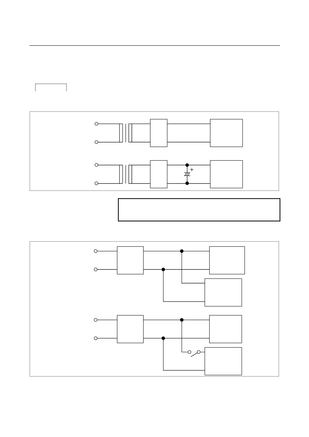
- Circuit configuration
The circuit configuration shown in
<1> and <2> below are not
permitted.
Prohibited
<1> Circuit examples in which the output voltage cannot be held at
the time of momentary disconnection (the voltage level lowers
below 21.6 V)
Example 1
Rectifier
AC input
circuit
CNC
Example 2
Rectifier
circuit
AC input
CNC
NOTE
A rectifier circuit performs full-wave rectification by
using diodes.
<2> Circuit examples in which the output voltage specification (21.6
V to 26.4 V) is exceeded by abrupt change in load
Example 1
βiSVM
Stabilized
AC input
βiSVPM
power
supply
Unit with
abrupt change
in load
Example 2
βiSVM
Stabilized
AC input
βiSVPM
power
supply
Unit with large
rush current
In case of
<2>, prepare an additional stabilized power supply
dedicated to a unit whose load changes abruptly, so that the βi SVM
and βi SVPM are not affected.
- 27 -
5.POWER SUPPLY
SVM
B-65322EN/02
5.2
POWER TRANSFORMER FOR EXPORTS
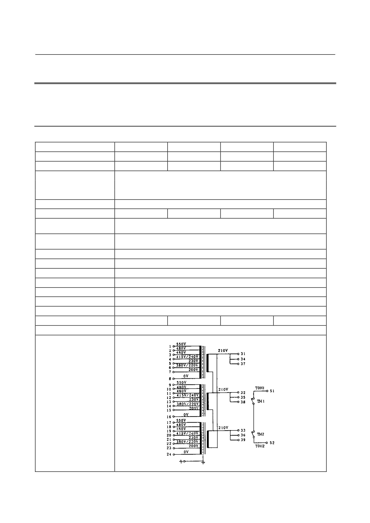
Use power transformer for an export when this servo amplifier unit is
used at a site where the line voltage is other than 200 to 240 VAC.
5.2.1
Specification
Table 5.2.1 Specification of power transformer
Ordering drawing number
A80L-0022-0005
A80L-0024-0006
A80L-0026-0003
A80L-0028-0001
FANUC drawing number
A80L-0022-0005
A80L-0024-0006
A80L-0026-0003
A80L-0028-0001
Rated capacity
2.2kVA
3.5kVA
5kVA
7.5kVA
200/220/230/240VAC (∆ connection)
Rated primary voltage
380/415/460/480/550VAC (Y connection)
±15%, 50/60Hz±2Hz; 3φ
Rated secondary voltage
210VAC
Rated secondary current
6.1A
9.6A
13.7A
20.6A
Voltage regulation at the
2%
secondary
Voltage deviation at the
±3%
secondary
Connection
∆-∆ connection or Y-∆ connection
Insulation
Class B (maximum allowable temperature : 130°C)
Ambient temperature
-20 to 55°C
Allowable temperature rise
135deg
Relative humidity
Max. 95%RH
Type
Dry type, natural air cooling type
Dielectric withstand voltage
2300VAC, for 1 minute
Weight
Max. 21kg
Max. 27kg
Max.36kg
Max. 42kg
Outline drawing
Fig. 8.1.3
Connection diagram
- 28 -
B-65322EN/02
SVM
5.POWER SUPPLY
5.2.2
How to Select a Transformer
Select a transformer according to the load condition and the model of
the motor for which the transformer is used. Each transformer has
secondary winding taps for three amplifiers so that it can be connected
to two or three amplifiers.
When connecting more than one amplifier, make a selection based on
the sum of the continuous current ratings of the individual motors.
- 29 -
6.INSTALLATION CONDITIONS AND NOTES SVM
B-65322EN/02
6
INSTALLATION CONDITIONS AND
NOTES
- 30 -

B-65322EN/02
SVM
6.INSTALLATION CONDITIONS AND NOTES
6.1
ENVIRONMENTAL CONDITIONS
Install a βi setting servo amplifier in a completely closed cabinet so
that the environment conditions indicated below can be satisfied.
(1) Ambient Temperature
Ambient temperature
0 to 55°C (operating)
-20 to 60°C (storage and transportation)
Ambient temperature of the accommodation cabinet 0 to 45°C
(2) Humidity
Usually, 95% RH or lower (no condensation)
(3) Vibration
No more than 0.5G during operation
(4) Atmosphere
Ensure that the electronic circuits are not exposed to corrosive
and conductive mist and waterdrops. (Note)
(5) Notes on installation
When installing an amplifier, consider the following:
(a) Ensure that the heat sink is not exposed to coolant, oil mist,
cuttings, and so forth. Otherwise, the cooling efficiency can
degrade, resulting in a failure to satisfy the characteristics of
the amplifier. Moreover, the life of semiconductors can be
adversely affected.
To introduce the open air for the heat sink, use an air filter
at the inlet.
Ensure that the cable inlet and outlet, door, and so forth are
sealed.
NOTE
The electronic circuits must be installed in an
environment of contamination level 2 defined in
IEC60664-1.
In order to satisfy contamination level 2 in a severe
environment for using machine tools, the servo
amplifier β series must be installed in a cabinet that
satisfy IP54.
If the cabinet does not have a structure for
preventing materials that adversely affect
amplifiers from getting into the cabinet, normal
operation and safety may fail. So, special care
should be taken.
(b) Ensure that dust, coolant, and so forth do not penetrate
through the exhaust vent. Moreover, ensure that the flow of
cooling wind is not interrupted.
(c) Ensure that the servo amplifier β series can be inspected,
removed, and reinstalled easily in maintenance.
- 31 -

6.INSTALLATION CONDITIONS AND NOTES SVM
B-65322EN/02
6.2
SELECTING A GROUND-FAULT CIRCUIT INTERRUPTER
Because the servo amplifier βi series uses the PWM inverter system
by transistors to drive a motor, high frequency leakage current flows
via the motor winding, power cable, and amplifier floating capacity to
ground. This may cause the ground-fault circuit interrupter or
ground-fault protective relay installed on the power supply side to
malfunction.
Therefore, when using a circuit breaker with a ground-fault circuit
interrupter, select an appropriate one having an inoperative current
value not smaller than the sum of the calculation results (a) and (b) to
prevent malfunctioning due to leakage current.
(a) Selection criterion per amplifier
Selection criterion:
2 mA per amplifier(*1)
(b) Selection criterion per motor
Selection criterion:
1 mA per motor(*1)
The following example shows how to use selection criteria <1> and
<2>:
Example:
When the system contains four βi SVM1 units
2 mA × 4 units (amplifiers) + 1 mA × 4 (motors) = 12 mA
→ Select a circuit breaker with an inoperative current of 12
mA or more(*2).
(A general ground-fault circuit interrupt applicable to this
example has a rated sensitivity current of 30 mA, and an
inoperative current of 15 mA.)
NOTE
1 The above selection criteria are provided in order
to select a circuit breaker with a ground-fault circuit
interrupter, and do not express accurate leakage
current values.
2 Depending on the frequency characteristic of the
ground-fault circuit interrupter, the circuit breaker
may malfunction. So, use a ground-fault circuit
interrupter usable for inverter circuits.
3 The above selection criteria are values in the
commercial frequency band. Some instruments
measuring leakage current may detect a high
frequency band and read larger values.
WARNING
Install a ground-fault circuit breaker.
To prevent fire and electric shock to a person, be
sure to install a ground-fault circuit breaker (for
inverter circuits).
- 32 -
B-65322EN/02
SVM
6.INSTALLATION CONDITIONS AND NOTES
6.3
NOISE PROTECTION
6.3.1
Separation of Signal Lines
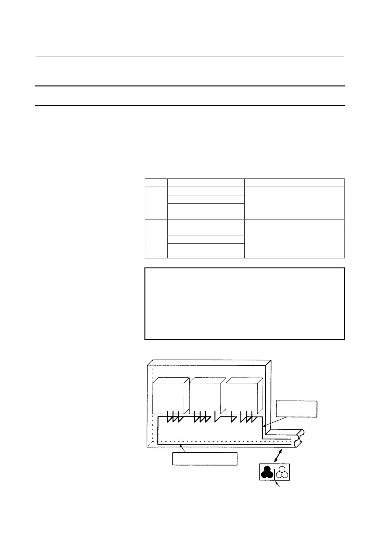
If a power cable and signal cable run close to each other, noise can be
induced. So, ensure that a power cable is separated from a signal cable.
When a power cable and signal line cannot be separated from each
other for a reason, minimize the distance by which the two cables run
in parallel. When conduits are used, run a power cable through one
conduit, and run a signal cable through another conduit.
Cable type
Group
Signal
Action
Amplifier input power line
Separate these cables from those of
Motor power line
group B by bundling them separately
A
Magnetic contactor drive coil
(Note 1) or by means of
(Note 3)
electromagnetic shielding (Note 2).
Cable connecting the control
Separate these cables from those of
unit and servo amplifier
group A by bundling them separately
B
Sensor cable
(Note 1) or by means of
electromagnetic shielding (Note 2). In
Position coder cable
addition, shielding must be provided.
NOTE
1 The bundle of group A cables must be separated
from the bundle of group B cables by at least 10 cm.
2 Electromagnetic shielding involves shielding
groups from each other by means of a grounded
metal (steel) plate.
3 Attach a noise suppressor such as a spark killer to
the magnetic contactor drive coil.
Cabinet
Control unit
Spindle
Servo
amplifier
amplifier
Cable of
group B
Duct
To operator's
panel, motor,
etc.
Cable of group A
Section of duct
Group A
Group B
Shielding plate
- 33 -
6.INSTALLATION CONDITIONS AND NOTES SVM
B-65322EN/02
6.3.2
Grounding
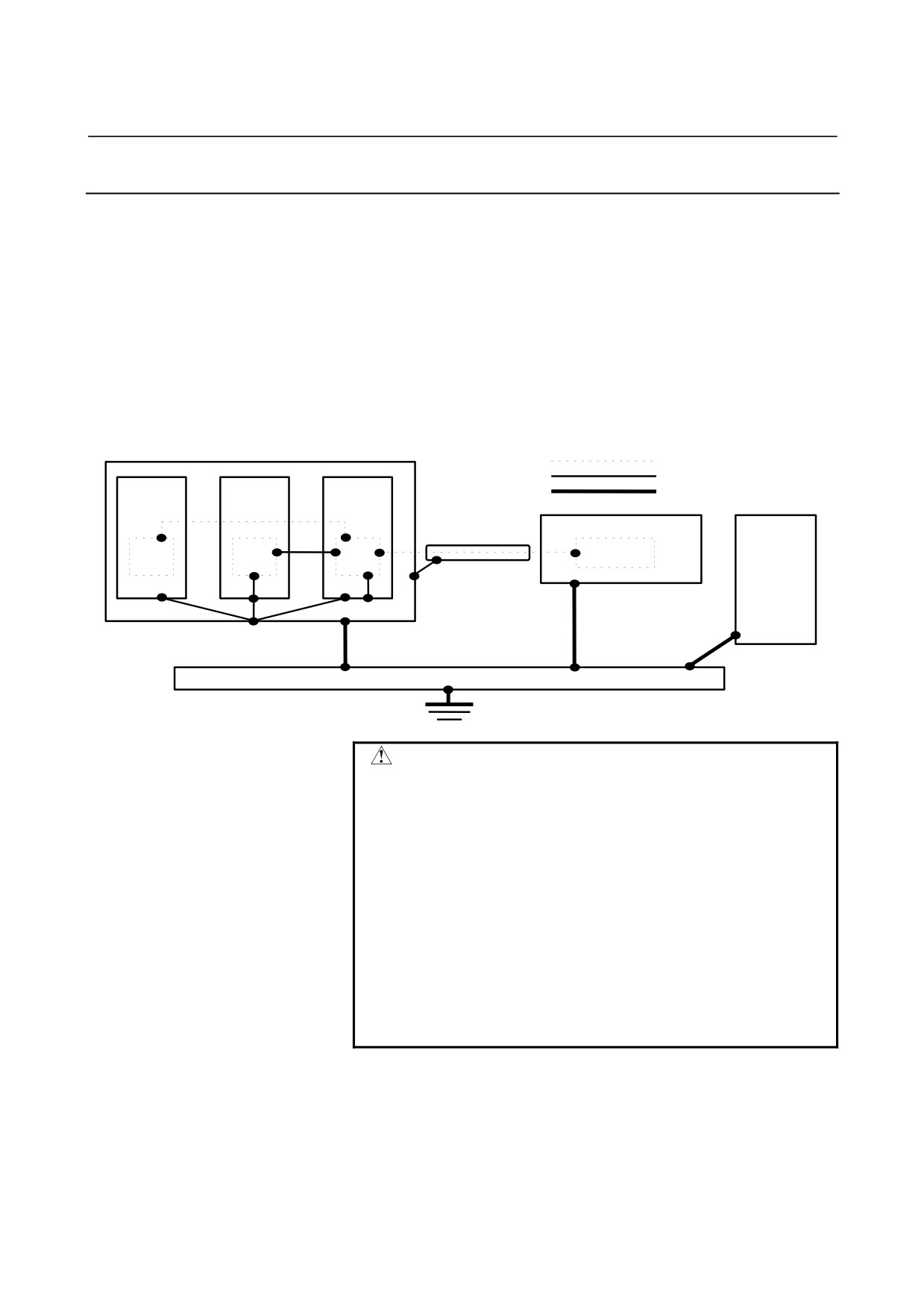
A CNC machine tool has three separate ground systems:
(1) Signal ground (SG) system
The signal ground (SG) system provides the reference potential
(0V) for the electrical signal system.
(2) Frame ground (FG) system
The frame ground (FG) system is provided to ensure safety and
to shield external and internal noise. For example, the equipment
frames, unit cases, panels, and interface cables connecting
devices are all shielded.
(3) System ground system
The system ground system is designed to connect each unit and
the inter-unit frame ground system to ground.
Signal Ground system
Flame Ground system
Power
Servo
CNC
System Ground system
magnetics
amplifier
unit
Operator’s panel
Main unit
Power magnetics unit
Distribution board
WARNING
[Warning on ground system wiring]
1 The ground resistance of the system ground must
not exceed 100 Ω (class-3 ground).
2 System ground connection cables must have a
sufficiently large cross-sectional area to enable
them to safely carry the current that will arise in the
event of a mishap such as a short-circuit. (In
general, a cross-sectional area no less than that of
the AC power line must be provided.)
3 The system ground connection cable shall be
integrated with the AC power line, such that power
cannot be supplied if the ground wire is
disconnected.
- 34 -
B-65322EN/02
SVM
6.INSTALLATION CONDITIONS AND NOTES
6.3.3
Noise Suppressor
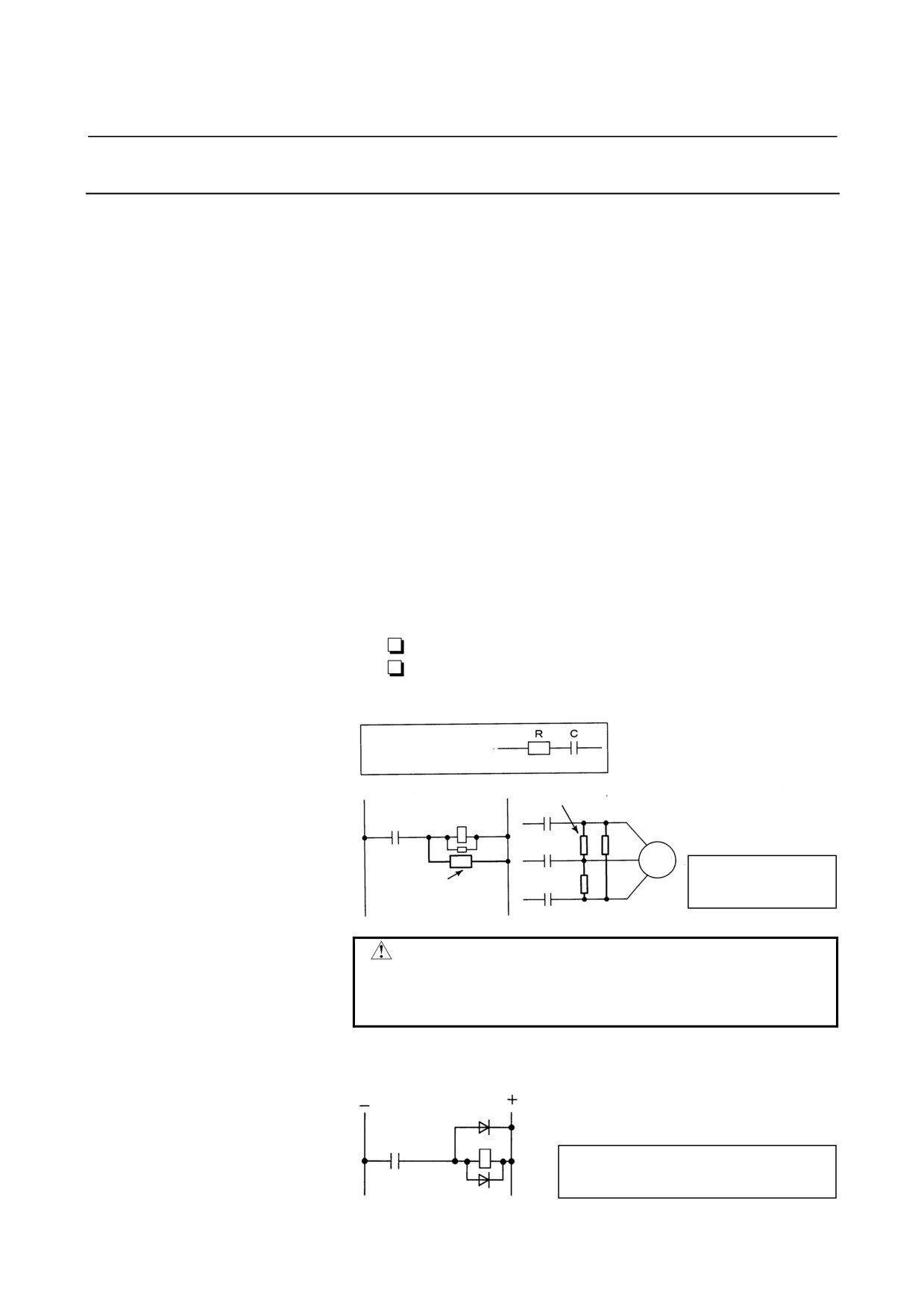
The AC/DC solenoid and relay are used in the power magnetics
cabinet.
A high pulse voltage is caused by coil inductance when these devices
are turned on or off.
This pulse voltage induced through the cable causes the electronic
circuits to be disturbed. In general, to reduce this pulse voltage, a
spark killer is used in AC circuits, while a diode is used in DC
circuits.
Spark killer
-
Use a spark killer consisting of a resistor and capacitor in series.
This type of spark killer is called a CR spark killer. (Use it under
AC)
(A varistor is useful in clamping the peak voltage of the pulse
voltage, but cannot suppress the sudden rise of the pulse voltage.
FANUC therefore recommends a CR spark killer.)
-
The reference capacitance and resistance of the spark killer shall
conform to the following based on the current (I(A)) and DC
resistance of the stationary coil:
Resistance (R)
: Equivalent DC resistance of the coil
Capacitance (C)
: I2/10 to I2/20 (µF)
I : Current at stationary state of the coil (A)
Equivalent circuit of
the spark killer
Spark killer
AC relay
Motor
Mount the noise
eliminator near a motor
Spark killer
or a relay coil.
CAUTION
Use a CR-type noise eliminator. Varistor-type noise
eliminators clamp the peak pulse voltage but
cannot suppress a sharp rising edge.
Diode
Diode (used for direct-current circuits)
Diode
DC relay
Use a diode which can withstand a voltage
up to two times the applied voltage and a
current up to two times the applied current.
- 35 -
6.INSTALLATION CONDITIONS AND NOTES SVM
B-65322EN/02
6.3.4
Cable Clamp and Shield Processing
-
Shield terminal processing
Process the terminal of the shield cover of a signal line according
to Chapter 10, "DETAILS OF CABLE CONNECTION".
-
Shield clamping
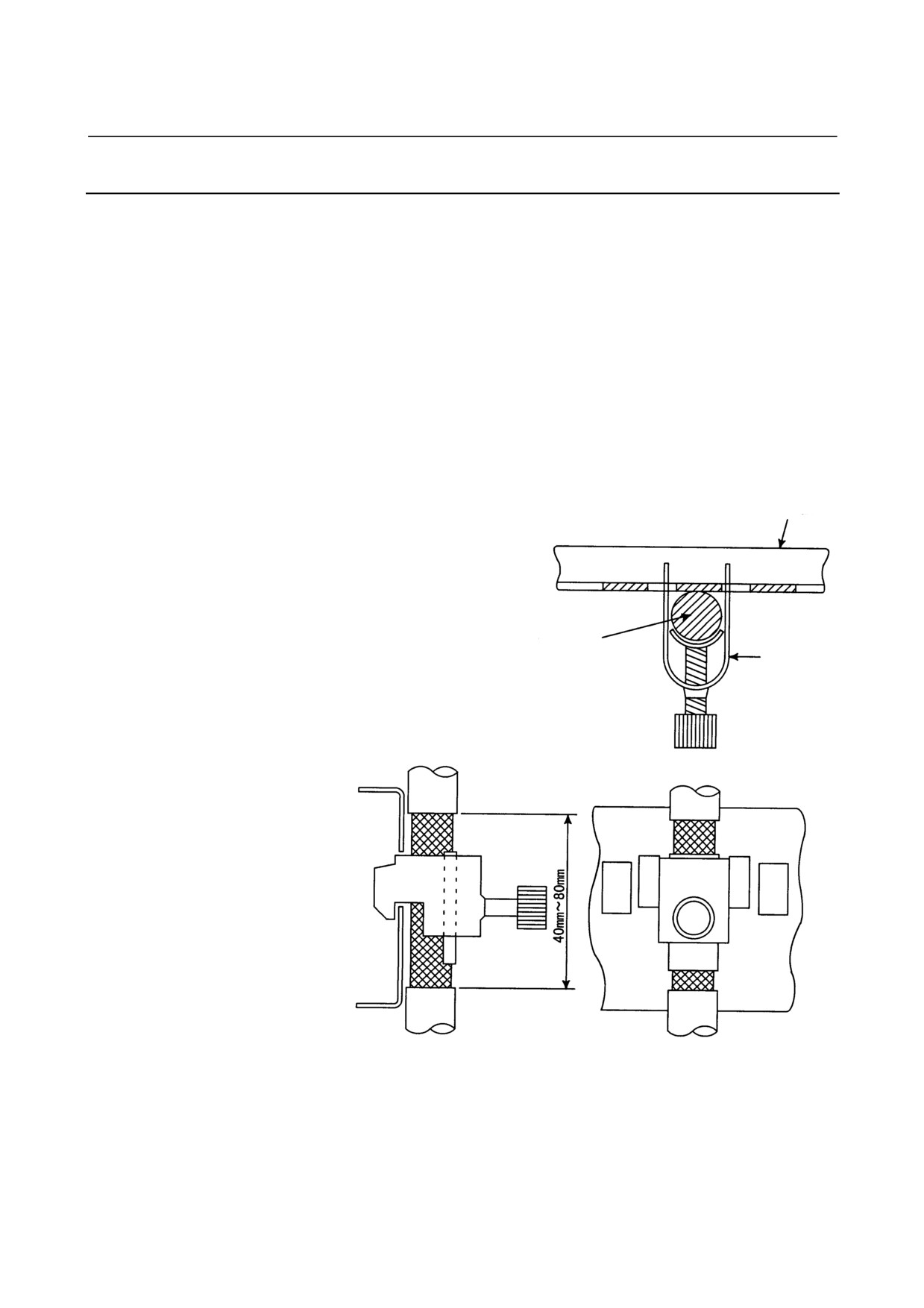
The amplifier cables that require shielding should be clamped by
the method shown below. This cable clamp treatment is for both
cable support and proper grounding of the shield. To insure
stable CNC system operation, follow this cable clamp method.
Partially peel out the sheath and expose the shield. Push and
clamp by the plate metal fittings for clamp at the part.
-
Installation of a ground plate
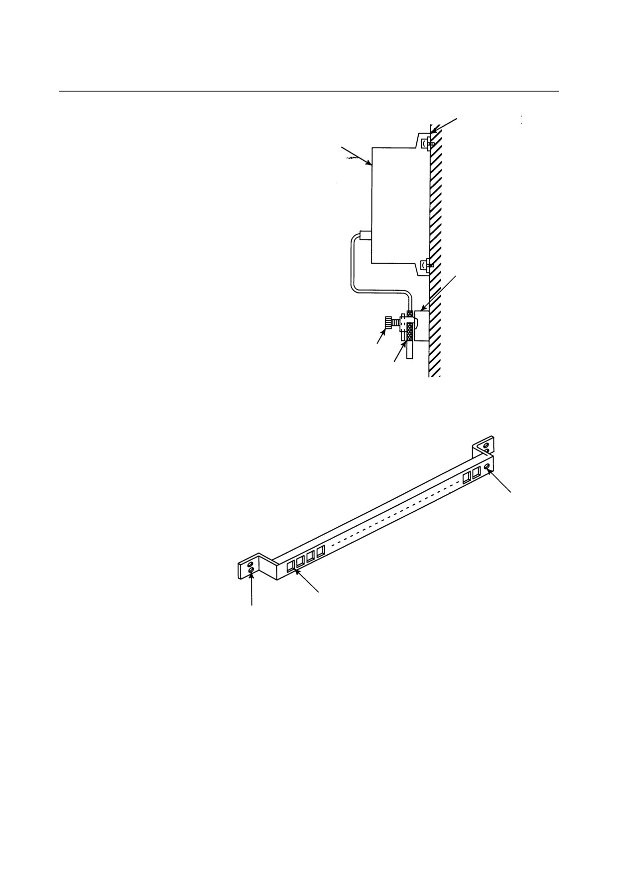
The user is to prepare a ground plate and install it according to
Fig. 6.3.4(b) to (e).
Ground plate
Cable
Metal
fittings
Fig.6.3.4(a) Cable clamp (1)
- 36 -
B-65322EN/02
SVM
6.INSTALLATION CONDITIONS AND NOTES
Machine side
installation
board
Control unit
Ground
plate
Metal fittings for
clamp
Shield cover
Fig.6.3.4(b) Cable clamp (2)
Prepare ground plate like the following figure.
Ground terminal
(grounded)
Hole for securing metal fitting clamp
Mount screw hole
Fig.6.3.4(c) Ground plate
- 37 -
6.INSTALLATION CONDITIONS AND NOTES SVM
B-65322EN/02
For the ground plate, use a metal plate of 2 mm or thicker, which
surface is plated with nickel.
Ground plate
Fig.6.3.4(d) Ground plate holes
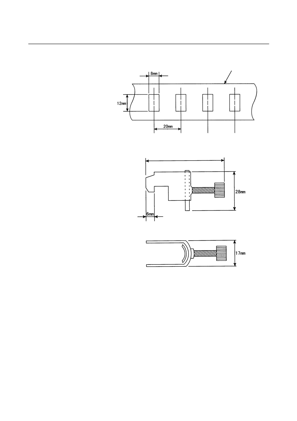
(Reference) Outer drawings of metal fittings for clamp.
Max. 55mm
Fig.6.3.4(e) Outer drawings of metal fittings for clamp
Ordering specification for metal fittings for clamp
A02B-0214-K001 (2 pieces)
- 38 -
B-65322EN/02
SVM
6.INSTALLATION CONDITIONS AND NOTES
6.4
INSTALLING LIGHTNING SURGE ABSORBERS
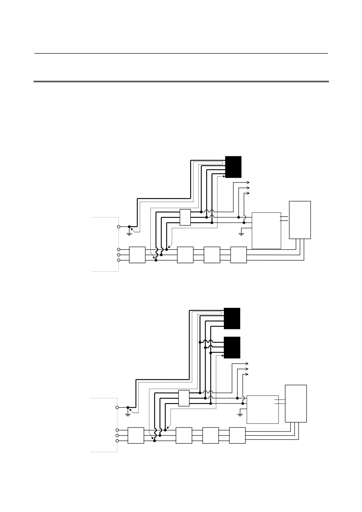
At the power input of the power magnetics cabinet, install a surge
absorber between the power lines and between each power line and a
ground to protect the unit from a voltage surge caused by lightning.
How to install the surge absorber is shown below.
(1) Surge absorber for three-phase input
When using an integrated lightning surge absorber between the
power lines and between each power line and a ground
Lightning surge absorber between power
lines and between each power line and
ground (R.C.M-601BUZ-4)
To other units
(a)
Control power
(b)
supply input
Stabilized
power
G
supply
βi SVM
(24 VDC)
Circuit breaker 2
Ground plate
(5A)
Main circuit
R
200VAC
S
power
input
T
Ground-fault circuit interrupter
Circuit
Magnetic
AC line filter
for power magnetics cabinet
breaker 1
contactor
When using separate lightning surge absorbers between the power
lines and between each power line and a ground
Lightning surge absorber between
each power line and ground
(R.A.V-781BXZ-2)
Lightning surge absorber between
power lines (R.A.V-781BYZ-2)
To other units
(a)
Control power
(b)
input
Stabilized
power supply
G
(24 VDC)
βi SVM
Circuit breaker 2
Ground plate
(5A)
Main circuit
R
power
200VAC
S
input
T
Ground-fault circuit interrupter
Circuit
Magnetic
AC line filter
for power magnetics cabinet
breaker 1
contactor
- 39 -
6.INSTALLATION CONDITIONS AND NOTES SVM
B-65322EN/02
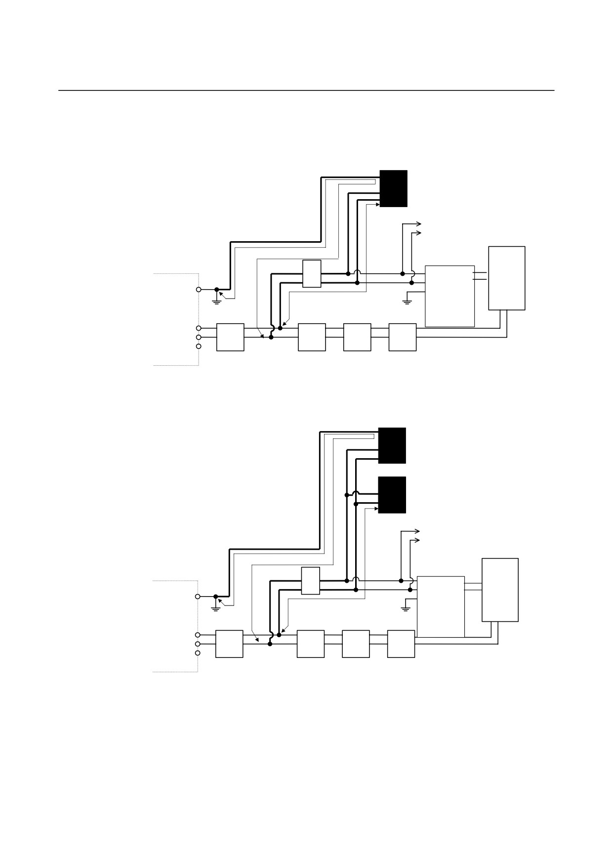
(2) Surge absorber for single-phase input
When using an integrated lightning surge absorber between the
power lines and between each power line and a ground
Lightning surge absorber between power
lines and between each line and ground
(R.C.M-601BUZ-4)
To other units
(a)
Control power
(b)
input
Stabilized
power
G
βi SVM
supply
(24 VDC)
Circuit breaker 2
Ground plate
(5A)
Main circuit
R
power
200VAC
S
T
input
Ground-fault circuit interrupter
Circuit
Magnetic
AC line filter
for power magnetics cabinet
breaker 1
contactor
When using separate lightning surge absorbers between the power
lines and between each power line and a ground
Lightning surge absorber between
each power line and ground
(R.A.V-781BXZ-4)
Lightning surge absorber between
power lines (R.A.V-781BYZ-2)
To other units
(a)
Control power
(b)
input
Stabilized
power
G
supply
βi SVM
(24 VDC)
Circuit breaker 2
Ground plate
(5A)
Main circuit
R
power
200VAC
S
input
T
Ground-fault circuit interrupter Circuit
Magnetic
AC line filter
for power magnetics cabinet breaker 1
contactor
- 40 -
B-65322EN/02
SVM
6.INSTALLATION CONDITIONS AND NOTES
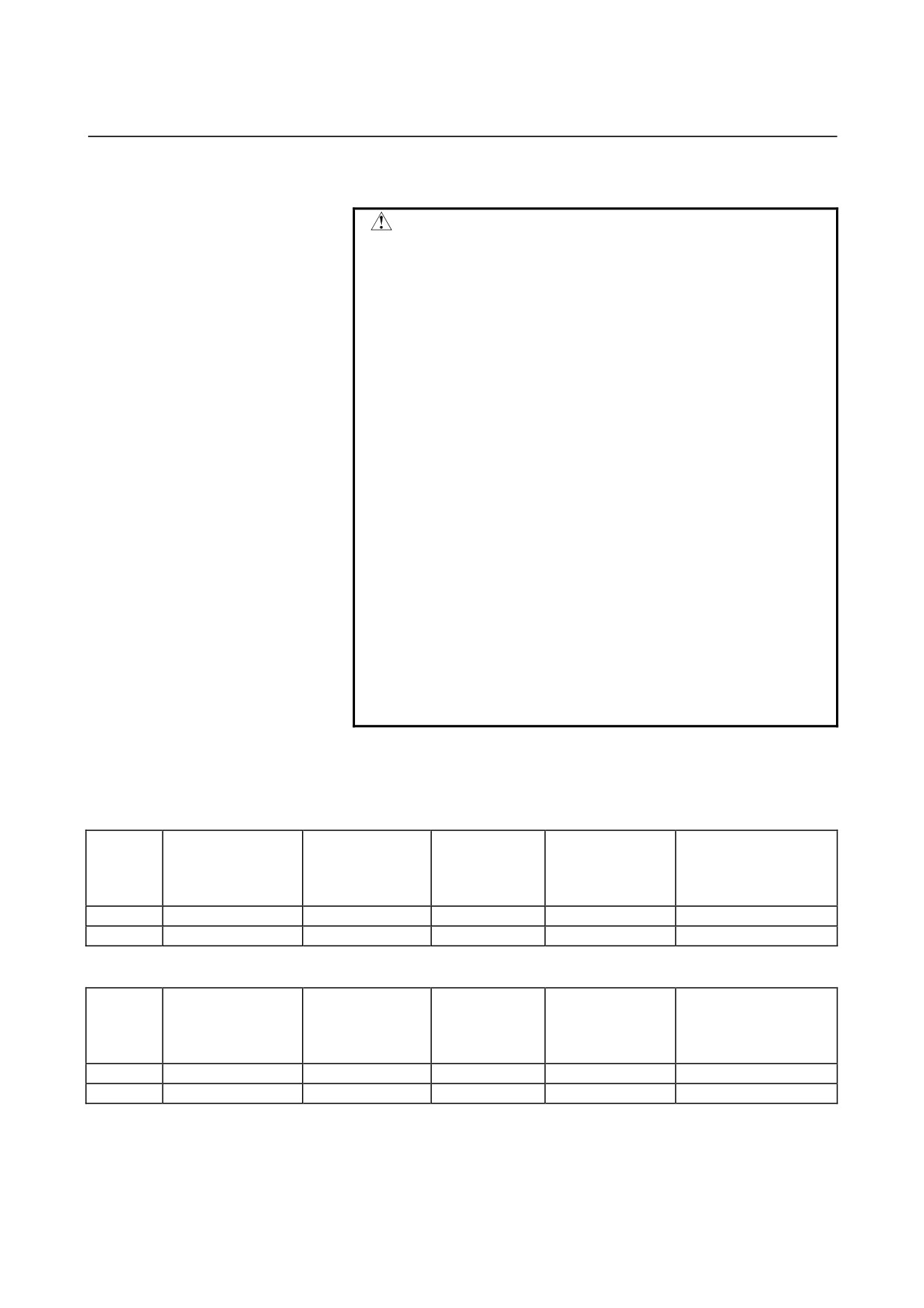
(3) Surge absorber for three-phase input
WARNING
1
Make the wires shown with thick line in the above
diagram as short as possible in order to increase
the effect of the lightning surge absorber.
Wire Cross section : At least 2mm2
Length : Keep the total wire length (a+b) to
within 2m,where a = length of wire
used to connect lightning surge
absorber (1) b = length of wire used
to connect lightning surge absorber
(2)
2
When performing a dielectric strength test by
applying an overvoltage (such as 1000 or 1500
VAC) to a power line, remove lightning surge
absorber (2) so that it will not operate.
3
The circuit protector (5A) is intended to protect the
lines if a lightning surge absorber is damaged due
to a surge that is higher than the maximum
allowable voltage of the surge absorber.
4
Usually, no current flows through the lightning
surge absorbers. So the circuit protector (5A) may
be used also for other sections (such as power
supply module control power and spindle motor fan
power).
The
following table lists commercially available lightning surge
absorbers.
Table 6.4(a) Lightning surge absorbers (not complying with the relevant standards)
Manufacturer's
Maximum
Maximum
Lightning
Maximum allowable
specification
Clamp voltage
allowable surge
allowable surge
surge
circuit voltage
Okaya Electric
[V]±10%
current
voltage
absorber
[Vrms]
Industries
8/20µsec [A]
1.2/50µsec [V]
<1>
R・A・V-781BYZ-2
783
1000
12000
300
<2>
R・A・V-781BXZ-2A
783
1000
12000
300
Table 6.4(b) Lightning surge absorbers (complying with the relevant standards)
Manufacturer's
Maximum
Maximum
Lightning
Maximum allowable
specification
Clamp voltage
allowable surge
allowable surge
surge
circuit voltage
Okaya Electric
[V]±10%
current
voltage
absorber
[Vrms]
Industries
8/20µsec [A]
1.2/50µsec [V]
<1>
R・A・V-781BYZ-2
783
1000
12000
300
<2>
R・A・V-781BXZ-4
783
1000
12000
300
- 41 -
7.PROTECTIVE GROUNDING
SVM
B-65322EN/02
7
PROTECTIVE GROUNDING
- 42 -