FANUC AC Servo Amplifiers βi Series. Description Manual (B-65322EN/02) - page 1
B-65322EN/02
SAFETY PRECAUTIONS
SAFETY PRECAUTIONS
This "Safety Precautions" section describes the precautions which
must be observed to ensure safety when using FANUC servo
amplifiers (including spindle amplifiers). Users of any servo amplifier
model are requested to read the "Safety Precautions" carefully before
first using the amplifier. Users should also read the relevant
description in this manual to become fully familiar with the functions
of the servo amplifier.
The users are basically forbidden to do any behavior or action not
mentioned in the "Safety Precautions." They are invited to ask
FANUC previously about what behavior or action is prohibited.
Contents
1.1 DEFINITION OF WARNING, CAUTION, AND NOTE
s-2
1.2 WARNINGS AND CAUTIONS RELATING TO
MOUNTING
s-3
1.2.1 Warning
s-3
1.2.2 Caution
s-5
1.2.3 Note
s-7
1.3 WARNINGS AND CAUTIONS RELATING
TO A PILOT RUN
s-8
1.3.1 Warning
s-8
1.3.2 Caution
s-9
1.4 WARNINGS AND CAUTIONS RELATING
TO MAINTENANCE
s-10
1.4.1 Warning
s-10
1.4.2 Caution
s-12
1.4.3 Note
s-13
s-1
SAFETY PRECAUTIONS
B-65322EN/02
1.1
DEFINITION OF WARNING, CAUTION, AND NOTE
This manual includes safety precautions for protecting the user and
preventing damage to the machine. Precautions are classified into
Warning and Caution according to their bearing on safety. Also,
supplementary information is described as a Note. Read the Warning,
Caution, and Note thoroughly before attempting to use the machine.
WARNING
Applied when there is a danger of the user being
injured or when there is a danger of both the user
being injured and the equipment being damaged if
the approved procedure is not observed.
CAUTION
Applied when there is a danger of the equipment
being damaged, if the approved procedure is not
observed.
NOTE
The Note is used to indicate supplementary
information other than Warning and Caution.
- Read this manual carefully, and store it in a safe place.
s-2
B-65322EN/02
SAFETY PRECAUTIONS
1.2
WARNINGS AND CAUTIONS RELATING TO MOUNTING
1.2.1
Warning
WARNING
-
Check the specification code of the amplifier.
Check that the delivered amplifier is as originally ordered.
-
Mount a ground fault interrupter.
To guard against fire and electric shock, fit the factory power
supply or machine with a ground fault interrupter (designed for
use with an inverter).
-
Securely ground the amplifier.
Securely connect the ground terminal and metal frame of the
amplifier and motor to a common ground plate of the power
magnetic cabinet.
-
Be aware of the weight of the amplifier and other
components.
Servo amplifiers and AC reactors are heavy. When transporting
them or mounting them in the cabinet, therefore, be careful not to
injured yourself or damage the equipment. Be particularly
carefull not to jam your fingers between the cabinet and
amplifier.
-
Never ground or short-circuit either the power supply lines
or power lines.
Protect the lines from any stress such as bending. Handle the
ends appropriately.
-
Ensure that the power supply lines, power lines, and signal
lines are securely connected.
A loose screw, loose connection, or the like will cause a motor
malfunction or overheating, or a ground fault.
Be extremely careful with power supply lines, motor power lines,
and DC link connections through which a large amount of
current passes, because a loose screw
(or poor contact in a
connector or poor connection between a connector terminal and a
cable) may cause a fire.
-
Insulate all exposed parts that are charged.
-
Never touch the regenerative discharge resistor or radiator
directly.
The surface of the radiator and regenerative discharge resistor
become extremely hot. Never touch them directly. An
appropriate structure should also be considered.
s-3
SAFETY PRECAUTIONS
B-65322EN/02
WARNING
-
Close the amplifier cover after completing the wiring.
Leaving the cover open presents a danger of electric shock.
-
Do not disassemble the amplifier.
-
Ensure that the cables used for the power supply lines and
power lines are of the appropriate diameter and temperature
ratings.
-
Do not apply an excessively large force to plastic parts.
If a plastic section breaks, it may cause internal damage, thus
interfering with normal operation. The edge of a broken section
is likely to be sharp and, therefore, presents a risk of injury.
s-4
B-65322EN/02
SAFETY PRECAUTIONS
1.2.2
Caution
CAUTION
-
Do not step or sit on the amplifier.
Also, do not stack unpacked amplifiers on top of each other.
-
Use the amplifier in an appropriate environment.
See the allowable ambient temperatures and other requirements,
given in the this manual.
-
Protect the amplifier from corrosive or conductive mist or
drops of water.
Use a filter if necessary.
-
Protect the amplifier from impact.
Do not place anything on the amplifier.
-
Do not block the air inlet to the radiator.
A deposit of coolant, oil mist, or chips on the air inlet will result
in a reduction in the cooling efficiency. In some cases, the
required efficiency cannot be achieved. The deposit may also
lead to a reduction in the useful life of the semiconductors.
Especially, when outside air is drawn in, mount filters on both
the air inlet and outlet. These filters must be replaced regularly.
So, an easy-to-replace type of filter should be used.
-
Connect the power supply lines and power lines to the
appropriate terminals and connectors.
-
Connect the signal lines to the appropriate connectors.
-
Before connecting the power supply wiring, check the supply
voltage.
Check that the supply voltage is within the range specified in this
manual, then connect the power supply lines.
-
Ensure that the combination of motor and amplifier is
appropriate.
-
Ensure that valid parameters are specified.
Specifying an invalid parameter for the combination of motor
and amplifier may not only prevent normal operation of the
motor but also result in damage to the amplifier.
-
Ensure that the amplifier and peripheral equipment are
securely connected.
Check that the magnetic contactor, circuit breaker, and other
devices mounted outside the amplifier are securely connected to
each other and that those devices are securely connected to the
amplifier.
s-5
SAFETY PRECAUTIONS
B-65322EN/02
CAUTION
-
Check that the amplifier is securely mounted in the power
magnetic cabinet.
If any clearance is left between the power magnetic cabinet and
the surface on which the amplifier is mounted, dust entering the
gap may build up and prevent the normal operation of the
amplifier.
-
Apply appropriate countermeasures against noise.
Adequate countermeasures against noise are required to maintain
normal operation of the amplifier. For example, signal lines must
be routed away from power supply lines and power lines.
s-6
B-65322EN/02
SAFETY PRECAUTIONS
1.2.3
Note
NOTE
-
Keep the nameplate clearly visible.
-
Keep the legend on the nameplate clearly visible.
-
After unpacking the amplifier, carefully check for any
damage.
-
Mount the amplifier in a location where it can be easily
accessed periodic inspection and daily maintenance.
-
Leave sufficient space around the machine to enable
maintenance to be performed easily.
Do not place any heavy objects such that they would interfere
with the opening of the doors.
-
Keep the parameter table and spare parts at hand.
Also, keep the specifications at hand. These items must be stored
in a location where they can be retrieved immediately.
-
Provide adequate shielding.
A cable to be shielded must be securely connected to the ground
plate, using a cable clamp or the like.
s-7
SAFETY PRECAUTIONS
B-65322EN/02
1.3
WARNINGS AND CAUTIONS RELATING TO A PILOT RUN
1.3.1
Warning
WARNING
-
Before turning on the power, check that the cables connected
to the power magnetic cabinet and amplifier, as well as the
power lines and power supply lines, are securely connected.
Also, check that no lines are slack.
-
Before turning on the power, ensure that the power magnetic
cabinet is securely grounded.
-
Before turning on the power, check that the door of the
power magnetic cabinet and all other doors are closed.
Ensure that the door of the power magnetic cabinet containing
the amplifier, and all other doors, are securely closed. During
operation, all doors must be closed and locked.
-
Apply extreme caution if the door of the power magnetic
cabinet or another door must be opened.
Only a person trained in the maintenance of the corresponding
machine or equipment should open the door, and only after
shutting off the power supply to the power magnetic cabinet (by
opening both the input circuit breaker of the power magnetic
cabinet and the factory switch used to supply power to the
cabinet). If the machine must be operated with the door open to
enable adjustment or for some other purpose, the operator must
keep his or her hands and tools well away from any dangerous
voltages. Such work must be done only by a person trained in the
maintenance of the machine or equipment.
-
When operating the machine for the first time, check that the
machine operates as instructed.
To check whether the machine operates as instructed, first
specify a small value for the motor, then increase the value
gradually. If the motor operates abnormally, perform an
emergency stop immediately.
-
After turning on the power, check the operation of the
emergency stop circuit.
Press the emergency stop button to check that the motor stops
immediately, and that the power being supplied to the amplifier
is shut off by the magnetic contactor.
-
Before opening a door or protective cover of a machine to
enable adjustment of the machine, first place the machine in
the emergency stop state and check that the motor has
stopped.
s-8
B-65322EN/02
SAFETY PRECAUTIONS
1.3.2
Caution
CAUTION
-
Note whether an alarm status relative to the amplifier is
displayed at power-up or during operation.
If an alarm is displayed, take appropriate action as explained in
the maintenance manual. If the work to be done requires that the
door of the power magnetic cabinet be left open, the work must
be carried out by a person trained in the maintenance of the
machine or equipment. Note that if some alarms are forcibly reset
to enable operation to continue, the amplifier may be damaged.
Take appropriate action according to the contents of the alarm.
-
Before operating the motor for the first time, mount and
adjust the position and speed sensors.
Following the instructions given in the maintenance manual,
adjust the position and speed sensors for the spindle so that an
appropriate waveform is obtained.
If the sensors are not properly adjusted, the motor may not rotate
normally or the spindle may fail to stop as desired.
-
If the motor makes any abnormal noise or vibration while
operating, stop it immediately.
Note that if operation is continued in spite of there being some
abnormal noise or vibration, the amplifier may be damaged. Take
appropriate corrective action, then resume operation.
-
Observe the ambient temperature and output rating
requirements.
The continuous output rating or continuous operation period of
some amplifiers may fall as the ambient temperature increases. If
the amplifier is used continuously with an excessive load applied,
the amplifier may be damaged.
s-9
SAFETY PRECAUTIONS
B-65322EN/02
1.4
Warnings and Cautions Relating to Maintenance
1.4.1
Warning
WARNING
-
Read the maintenance manual carefully and ensure that you
are totally familiar with its contents.
The maintenance manual describes daily maintenance and the
procedures to be followed in the event of an alarm being issued.
The operator must be familiar with these descriptions.
-
Notes on replacing a fuse or PC board
1)
Before starting the replacement work, ensure that the circuit
breaker protecting the power magnetic cabinet is open.
2)
Check that the red LED that indicates that charging is in
progress is not lit.
The position of the charging LED on each model of
amplifier is given in this manual. While the LED is lit,
hazardous voltages are present inside the unit, and thus
there is a danger of electric shock.
3)
Some PC board components become extremely hot. Be
careful not to touch these components.
4)
Ensure that a fuse having an appropriate rating is used.
5)
Check the specification code of a PC board to be replaced.
If a modification drawing number is indicated, contact
FANUC before replacing the PC board.
Also, before and after replacing a PC board, check its pin
settings.
6)
After replacing the fuse, ensure that the screws are firmly
tightened. For a socket-type fuse, ensure that the fuse is
inserted correctly.
7)
After replacing the PC board, ensure that it is securely
connected.
8)
Ensure that all power lines, power supply lines, and
connectors are securely connected.
-
Take care not to lose any screws.
When removing the case or PC board, take care not to lose any
screws. If a screw is lost inside the nit and the power is turned on,
the machine may be damaged.
s-10
B-65322EN/02
SAFETY PRECAUTIONS
WARNING
-
Notes on replacing the battery of the absolute Pulsecoder
Replace the battery only while the power is on. If the battery is
replaced while the power is turned off, the stored absolute
positioning data will be lost. Some βi series servo amplifier
modules have batteries in their servo amplifiers. To replace the
battery of any of those models, observe the following procedure:
Open the door of the power magnetic cabinet; Leave the control
power of the power supply module on; Place the machine in the
emergency stop state so that the power being input to the
amplifier is shut off; Then, replace the battery. Replacement
work should be done only by a person who is trained in the
related maintenance and safety requirements. The power
magnetic cabinet in which the servo amplifier is mounted has a
high-voltage section. This section presents a severe risk of
electric shock.
-
Check the alarm number.
If the machine stops upon an alarm being issued, check the alarm
number. Some alarms indicate that a component must be replaced.
If the power is reconnected without first replacing the failed
component, another component may be damaged, making it
difficult to locate the original cause of the alarm.
-
Before resetting an alarm, ensure that the original cause of
the alarm has been removed.
-
Contact FANUC whenever a question relating to
maintenance arises.
-
Notes on removing the amplifier
Before removing the amplifier, first ensure that the power is shut
off. Be careful not to jam your fingers between the power
magnetic cabinet and amplifier.
s-11
SAFETY PRECAUTIONS
B-65322EN/02
1.4.2
Caution
CAUTION
-
Ensure that all required components are mounted.
When replacing a component or PC board, check that all
components, including the snubber capacitor, are correctly
mounted. If the snubber capacitor is not mounted, for example,
the IPM will be damaged.
-
Tighten all screws firmly.
-
Check the specification code of the fuse, PC board, and other
components.
When replacing a fuse or PC board, first check the specification
code of the fuse or PC board, then mount it in the correct position.
The machine will not operate normally if a fuse or PC board
having other than the correct specification code is mounted, or if
a fuse or PC board is mounted in the wrong position.
-
Mount the correct cover.
The cover on the front of the amplifier carries a label indicating a
specification code. When mounting a previously removed front
cover, take care to mount it on the unit from which it was
removed.
-
Notes on cleaning the heat sink and fan
1)
A dirty heat sink or fan results in reduced semiconductor
cooling efficiency, which degrades reliability. Periodic
cleaning is necessary.
2)
Using compressed air for cleaning scatters the dust. A
deposit of conductive dust on the amplifier or peripheral
equipment will result in a failure.
3)
To clean the heat sink, do so only after turning the power
off and ensuring that the heat sink has cooled to room
temperature. The heat sink becomes extremely hot, such
that touching it during operation or immediately after
power-off is likely to cause a burn. Be extremely careful
when touching the heat sink.
-
Unless otherwise specified, do not insert or remove any
connector while the power is turned on. Otherwise, the
amplifier may fail.
s-12
B-65322EN/02
SAFETY PRECAUTIONS
1.4.3
Note
NOTE
-
Ensure that the battery connector is correctly inserted.
If the power is shut off while the battery connector is not
connected correctly, the absolute position data for the machine
will be lost.
-
Store the manuals in a safe place.
The manuals should be stored in a location where they can be
accessed immediately it so required during maintenance work.
-
Notes on contacting FANUC
Inform FANUC of the details of an alarm and the specification
code of the amplifier so that any components required for
maintenance can be quickly secured, and any other necessary
action can be taken without delay.
s-13
B-65322EN/02
TABLE OF CONTENTS
TABLE OF CONTENTS
SAFETY PRECAUTIONS
s-1
I. SVM
1
OVERVIEW
3
2
CONFIGURATION
4
2.1
SVM1-4i AND SVM1-20i
5
2.2
SVM1-40i AND SVM1-80i
6
2
CONFIGURATION
4
2.1
SVM1-4i AND SVM1-20i
5
2.2
SVM1-40i AND SVM1-80i
6
3
SPECIFICATIONS
7
3.1
SPECIFICATIONS
8
3.2
APPLICABLE MOTORS
8
3.3
SELECTING CIRCUIT BREAKER, MAGNETIC CONTACTOR, AND
AC LINE FILTER
9
3.3.1
Selecting Circuit Breaker
9
3.3.2
Selecting Magnetic Contactor
10
3.3.3
AC Line Filter
10
3.4
COOLING FAM MOTORS
11
3.4.1
Models Requiring Cooling Fan motors
11
3.4.2
Installing a Separate Cooling Fan motor
11
3.5
DERATING
12
3.6
SEPARATED REGENERATIVE DISCHARGE RESISTOR
13
3.6.1
When No Separated Regenerative Discharge Resistor Is Needed
13
3.6.2
When a Separated Regenerative Discharge Resistor Is Needed
15
3.6.3
When Amplifier Models SVM-40i and SVM-80i Are Used
17
4
ORDERING INFORMATION
22
5
POWER SUPPLY
23
5.1
INPUT POWER SUPPLY
24
5.1.1
Three-phase Input Power Supply for Motor Power
24
5.1.2
Single-phase Input Power Supply for Motor Power
24
5.1.3
Single-phase Input for Control Power
24
5.2
POWER TRANSFORMER FOR EXPORTS
28
c-1
TABLE OF CONTENTS
B-65322EN/02
5.2.1
Specification
28
5.2.2
How to Select a Transformer
29
6
INSTALLATION CONDITIONS AND NOTES
30
6.1
ENVIRONMENTAL CONDITIONS
31
6.2
SELECTING A GROUND-FAULT CIRCUIT INTERRUPTER
32
6.3
NOISE PROTECTION
33
6.3.1
Separation of Signal Lines
33
6.3.2
Grounding
34
6.3.3
Noise Suppressor
35
6.3.4
Cable Clamp and Shield Processing
36
6.4
INSTALLING LIGHTNING SURGE ABSORBERS
39
7
PROTECTIVE GROUNDING
42
7.1
SVM1-4i and SVM1-20i (FSSB Interface)
43
7.2
SVM1-40i and SVM1-80i (FSSB Interface)
44
8
EXTERNAL DIMENSIONS / PANEL CUT-OUT DRAWINGS /
MAINTENANCE AREA
45
8.1
EXTERNAL DIMENSIONS
46
8.1.1
External Dimensions of SVM1-4i and SVM1-20i
46
8.1.2
External Dimensions of SVM1-40i and SVM1-80i
47
8.1.3
External Dimensions of Fan Unit (A06B-6134-K003)
48
8.1.4
External Dimensions of Fan Unit (A06B-6134-K002)
49
8.1.5
Discharge Resistor
50
8.1.6
AC Line Filter
53
8.1.7
Transformer for Exports
55
8.1.8
Battery Case
55
8.1.9
Lightning Surge Absorbers
56
8.2
PANEL CUT-OUT DRAWINGS
58
8.2.1
SVM1-4i and SVM1-20i
58
8.2.2
SVM1-40i and SVM1-80i
59
8.2.3
Discharge Resistor
60
8.3
MAINTENANCE AREA
62
8.3.1
Maintenance Area for the SVM1-4i and SVM1-20i
62
8.3.2
Maintenance Area for the SVM1-40i and SVM1-80i
63
9
TOTAL CONNECTION DIAGRAM
65
9.1
CONNECTION DIAGRAM
66
9.1.1
SVM1-4i and SVM1-20i
66
c-2
B-65322EN/02
TABLE OF CONTENTS
9.1.2
SVM1-40i and SVM1-80i
68
9.2
CONNECTOR LOCATION
70
9.2.1
SVM1-4i and SVM1-20i
70
9.2.2
SVM1-40i and SVM1-80i
71
9.2.3
Connection Tools
72
9.2.4
Details of Cable K1
73
9.2.4.1
Servo motor αi, αis series, Servo motor βis series
(β0.4/5000is to β22/2000is)
73
9.2.4.2
Servo motor βis series (β0.2/5000is, β0.3/5000is)
75
9.2.5
Details of Cable K2
77
9.2.5.1
Details of connectors
77
9.2.5.2
Selecting cables (general)
80
9.2.5.3
Details of input cables
81
9.2.6
Details of Cable K3
82
9.2.6.1
Details of connectors
82
9.2.6.2
Details of cables (general)
83
9.2.6.3
Power cable for servo motor
84
9.2.7
Details of Cables K4 and K5
85
9.2.7.1
SVM1-4i and SVM1-20i
85
9.2.7.2
SVM1-40i and SVM1-80i
87
9.2.8
Details of Cable K6
89
9.2.9
Details of Cable K7
90
9.2.10
Details of Cable K8
91
9.2.11
Details of Cable K9
93
9.2.12
Details of Cable K10
94
9.2.13
Details of Cable K11
96
9.3
HANDLING OF EXTERNAL MAGNETIC CONTACTORS
97
10
HEAT DISSIPATION
98
II. SVPM
1 OVERVIEW
101
2 CONFIGURATION
102
3 SPECIFICATIONS
103
3.1
SPECIFICATIONS
104
3.2
COOLING FAN MOTOR
106
3.3
HOW TO OBTAIN A POWER SUPPLY CAPACITY
106
3.4
APPLICABLE MOTORS
107
3.5
CIRCUIT BREAKER, MAGNETIC CONTACTOR, AND AC REACTOR
108
c-3
TABLE OF CONTENTS
B-65322EN/02
3.5.1
AC Line Filter and Magnetic Contactor
108
3.5.2
AC Reactor
109
3.6
SPINDLE AXIS TYPES (#A AND #C) AND APPLICABLE SENSORS
110
3.7
DERATING
111
4
ORDERING INFORMATION
112
5
POWER SUPPLY
113
5.1
INPUT POWER SUPPLY
114
5.1.1
Three-phase Input Power Supply for Motor Power
114
5.1.2
Single-phase Input for Control Power
115
5.2
POWER TRANSFORMER FOR EXPORTS
116
6
INSTALLATION CONDITIONS AND NOTES
119
6.1
ENVIRONMENTAL CONDITIONS
120
6.2
Selecting a Ground-Fault Circuit Interrupter
120
6.3
NOISE PROTECTION
120
6.4
INSTALLING LIGHTNING SURGE ABSORBERS
121
7
PROTECTIVE GROUNDING
123
8
EXTERNAL DIMENSIONS / PANEL CUT-OUT DRAWINGS /
MAINTENANCE AREA
124
8.1
EXTERNAL DIMENSIONS
125
8.1.1
External Dimensions of SVPM
125
8.1.2
External Dimensions of Fan Unit (A06B-6134-K001)
125
8.1.3
AC Reactor Unit
126
8.1.4
Power Transformer
127
8.1.5
Circuit Breaker
130
8.1.6
Magnetic Contactors
131
8.1.7
Lightning Surge Protector
133
8.2
PANEL CUT-OUT DRAWINGS
134
8.3
MAINTENANCE AREA
136
8.4
DUCT
138
9
TOTAL CONNECTION DIAGRAM
140
9.1
CONNECTION DIAGRAM
140
9.2
CONNECTOR LOCATION
141
9.3
DETAILED DESCRIPTONS OF CONNECTIONS
142
9.3.1
Common
142
9.3.1.1
Details of cable K1
142
c-4
B-65322EN/02
TABLE OF CONTENTS
9.3.1.2
Details of cable K6
144
9.3.1.3
Details of cable K7
145
9.3.1.4
Details of cable K69
146
9.3.1.5
Details of cable K70
146
9.3.1.6
Details of cable K21
148
9.3.1.7
Details of cable K22
150
9.3.1.8
Details of cable K27
152
9.3.1.9
Details of cable K28
153
9.3.2
Spindle Motor
155
9.3.2.1
Details of cable K10
155
9.3.2.2
Details of cable K12
156
9.3.2.3
Details of cable K14
158
9.3.2.4
Details of cable K16
160
9.3.2.5
Details of cable K17
162
9.3.2.6
Details of cable K33
164
9.3.2.7
Details of cable K71
169
9.3.2.8
Details of cable K79
172
9.4
DETAILS OF CONNECTORS
173
9.4.1
20-Pin Half-Pitch Connectors
173
9.4.2
Tyco Electronics AMP D-5000 Series Connector
174
10
HEAT DISSIPATION
176
11
POWER CABLE FOR SERVO MOTOR AND AMPLIFIER
179
11.1
SELECTING A POWER CABLE
180
11.2
SAMPLE POWER CABLES SELECTED FOR SERVO MOTORS
(REFERENCE)
182
11.3
SAMPLE POWER CABLES SELECTED FOR SPINDLE MOTORS
(REFERENCE)
182
III. I/O Link
1 OVERVIEW
185
2 CONFIGURATION
186
2.1
SVM1-4i AND SVM1-20i
187
2.2
SVM1-40i AND SVM1-80i
188
3 SPECIFICATIONS
189
3.1
SPECIFICATIONS
190
3.2
APPLICABLE MOTORS
191
3.3
SELECTING CIRCUIT BREAKER, MAGNETIC CONTACTOR, AND
AC LINE FILTER
191
c-5
TABLE OF CONTENTS
B-65322EN/02
3.3.1
Selecting Circuit Breaker
191
3.3.2
Selecting Magnetic Contactor
191
3.3.3
Selecting AC Line Filter
191
3.4
COOLING FAM MOTORS
192
3.4.1
Installing the Cooling Fan Motor in the SVM1-4i and SVM1-20i
192
3.4.2
SVM1-80i
192
3.5
DERATING
193
3.6
SEPARATED REGENERATIVE DISCHARGE RESISTOR
193
4
ORDERING INFORMATION
194
5
POWER SUPPLY
195
5.1
INPUT POWER SUPPLY
196
5.1.1
Three-phase Input Power Supply for Motor Power
196
5.1.2
Single-phase Input Power Supply for Motor Power
196
5.1.3
Control Power
196
5.1.3.1
Sequence for turning on control power supply
196
5.2
POWER TRANSFORMER FOR EXPORTS
196
6
INSTALLATION CONDITIONS AND NOTES
197
7
GROUNDING
198
7.1
SVM1-4i AND SVM1-20i
199
7.2
SVM1-40i and SVM1-80i
200
8
EXTERNAL DIMENSIONS / PANEL CUT-OUT DRAWINGS /
MAINTENANCE AREA
201
8.1
EXTERNAL DIMENSIONS
202
8.1.1
SVM1-4i and SVM1-20i
202
8.1.2
SVM1-40i and SVM1-80i
203
8.1.3
Fan Unit (A06B-6134-K002)
204
8.1.4
Separated Regenerative Discharge Resistor
204
8.1.5
AC Line Filter
204
8.1.6
Transformer for Exports
204
8.1.7
Battery Case (for Size D Alkaline Battery)
204
8.1.8
Lightning Surge Absorbers
204
8.2
PANEL CUT-OUT DRAWINGS
204
8.3
MAINTENANCE AREA
205
8.3.1
Maintenance Area for the SVM1-4i and SVM1-20i
205
8.3.2
Maintenance Area for the SVM1-40i
205
c-6
B-65322EN/02
TABLE OF CONTENTS
8.3.3
Maintenance Area for the SVM1-80i
205
9
TOTAL CONNECTION DIAGRAM
206
9.1
CONNECTION DIAGRAM
207
9.1.1
SVM1-4i and SVM1-20i
207
9.1.2
SVM1-40i and SVM1-80i
209
9.1.3
SVM1-4i and SVM1-20i
211
9.1.4
SVM1-40i and SVM1-80i
213
9.2
CONNECTOR LOCATION
215
9.2.1
SVM1-4i and SVM1-20i
215
9.2.2
SVM1-40i and SVM1-80i
216
9.2.3
Connection Tools
217
9.2.4
Details of Cable K1
217
9.2.4.1
Servo motor αi, αis series, Servo motor βis series
(β0.4/5000is to β22/2000is)
217
9.2.4.2
Servo motor βis series (β0.2/5000is, β0.3/5000is)
218
9.2.5
Details of Cable K2
219
9.2.6
Details of Cable K3
219
9.2.7
Details of Cables K4 and K5
219
9.2.8
Details of Cable K6
219
9.2.9
Details of Cable K7
220
9.2.9.1
Connection of external magnetic contactor when βi SVM FSSB interface is
used together
221
9.2.10
Details of Cable K8
222
9.2.11
Details of Cable K9
222
9.2.12
Details of Cable K10
222
9.2.13
Details of Cable K11
222
9.2.14
Details of Cable K20 (Connection of FANUC I/O Link)
223
9.2.14.1 Overview
223
9.2.14.2 Connection of FANUC I/O Link by electric cable
224
9.2.14.3 Connection of FANUC I/O Link by optical fiber cable
225
9.2.15
Details of Cable K21 (Internal DI Connection)
226
9.2.15.1 Signals
226
9.2.15.2
*+OT, *-OT, and *RILK(*DEC)
227
9.2.15.3
Skip signal interface
228
9.2.16
Connection to External Pulse Generator
229
9.2.16.1 Connection when differential type A/B phase pulse generator is used
230
9.2.16.2 Connection when FANUC's manual pulse generator is used
231
9.2.17
Connection to Servo Check Board
238
c-7
TABLE OF CONTENTS
B-65322EN/02
10 HEAT DISSIPATION
239
APPENDIX
A CONNECTING THE REACTOR AND LINE FILETER
243
A.1
OVERVIEW
244
A.2
CONNECTION EXAMPLES
245
c-8
B-65322EN/02
SVM
1.OVERVIEW
1
OVERVIEW
The βi SVM FSSB interface has the following features:
(1) Because a power supply is incorporated, a compact system can
be built for 1- or 2-axis machining.
(2) One-axis AC servo system with excellent cost performance
(3) The FSSB interface, which is the standard interface of FANUC, is
supported.
(4) This unit has a small installation area and volume.
(5) The unit is designed in compliance with the following safety
standards:
- EN50178
- UL508C
- CSA C22.2
- EN61000-6-2
- EN55011
(6) This one-axis AC servo amplifier is suitable for the servo motor
βi series, which is suitable for feed axes of machining tools and
for applications of their peripheral equipment and industrial
machines, and the servo motor αi series, which is suitable for
feed axes.
- 3 -
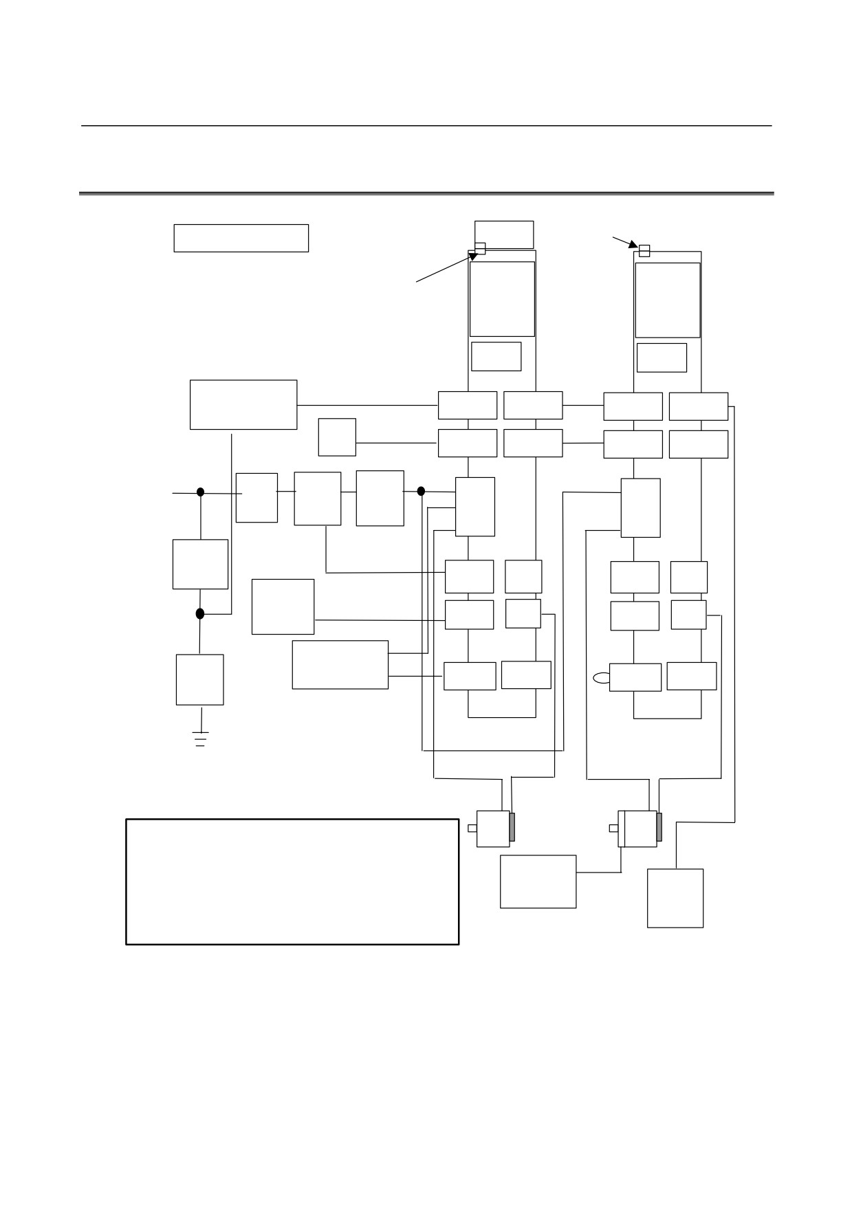
B-65322EN/02
SVM
2.CONFIGURATION
2.1
SVM1-4i AND SVM1-20i
Fan unit
Dummy connector for fan
4-A type, 20-A type
βi
βi
Connector for fan
SVM
SVM
20A
4A
FUSE
FUSE
Stabilized
+24V etc
power supply
CXA19B
CXA19A
CXA19B
CXA19A
24 VDC
NC
Optical cable
COP10B
COP10A
COP10B
COP10A
3-phase : 200 to 240 VAC
1-phase : 220 to 240 VAC
Optical cable
Circuit
Magnetic
AC
CZ7
CZ7
breaker
contactor
line
filter
5 A
Magnetic contactor
Circuit
control signal
breaker
CX29
JX5
CX29
JX5
Emergency
stop switch
Emergency stop signal
CX30
JF1
CX30
JF1
Separated
Lightning
regenerative
surge
discharge resistor
CXA20
CX5X
CXA20
CX5X
absorber
CAUTION
1 A circuit breakers, magnetic contactor, and AC line filter are
always required.
2 Use the stabilized 24VDC power supply for the amplifier.
24 V power
24VDC power supply for the amplifier and 24VDC power supply
supply for
Battery
for the motor brake cannot be shared.
motor brake
case
3 The cabling of CX29 and CX30 of the second and subsequent
amplifiers may be omitted. For details, see "TOTAL
CONNECTION DIAGRAM".
- 5 -
2.CONFIGURATION
SVM
B-65322EN/02
2.2
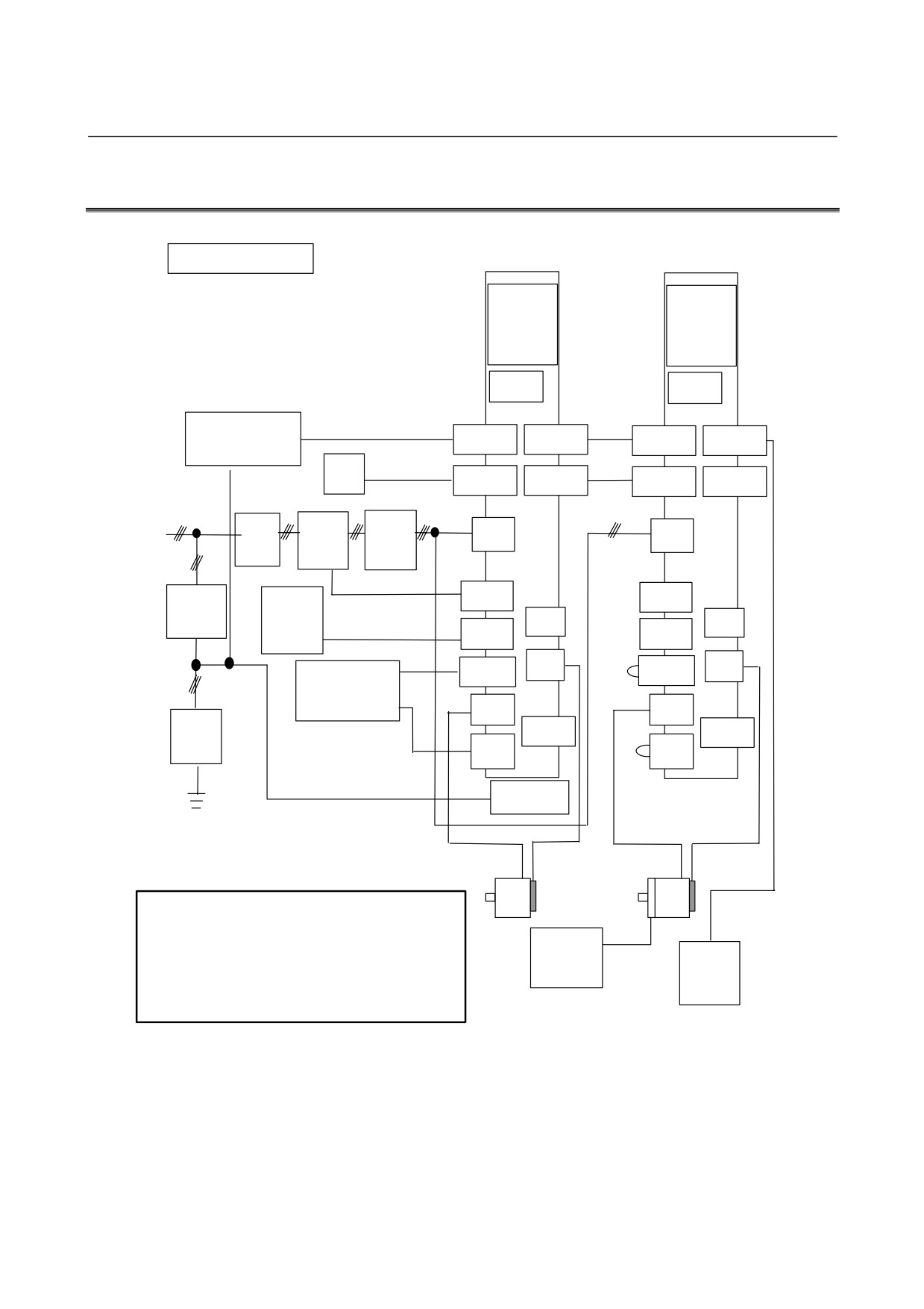
SVM1-40i AND SVM1-80i
40-A type, 80-A type
βi
βi
SVM
SVM
80A
40A
FUSE
FUSE
Stabilized
+24V etc
power supply
CXA19B
CXA19A
CXA19B
CXA19A
24 VDC
NC
Optical cable
COP10B
COP10A
COP10B
COP10A
3-phase
200 to 240 VAC
Optical cable
Circuit
Magnetic
AC line
CZ4
CZ4
breaker
contactor
filter
Magnetic contactor
signal
CX29
5 A
Emergency
CX29
Circuit
stop switch
breaker
Emergency
JX5
JX5
stop signal
CX30
CX30
JF1
JF1
CXA20
CXA20
Separated
regenerative
discharge
CZ5
CZ5
resistor
Lightning
CX5X
CX5X
surge
absorber
CZ6
CZ6
Fan unit
CAUTION
1 A circuit breakers, magnetic contactor, and AC line filter
are always required.
2 Use the stabilized 24VDC power supply for the amplifier.
24 V
24VDC power supply for the amplifier and 24VDC power
power
Battery
supply for the motor brake cannot be shared.
supply for
case
3 The cabling of CX29 and CX30 of the second and
motor
subsequent amplifiers may be omitted. For details, see
"TOTAL CONNECTION DIAGRAM".
- 6 -
B-65322EN/02
SVM
3.SPECIFICATIONS
3
SPECIFICATIONS
- 7 -
3.SPECIFICATIONS
SVM
B-65322EN/02
3.1
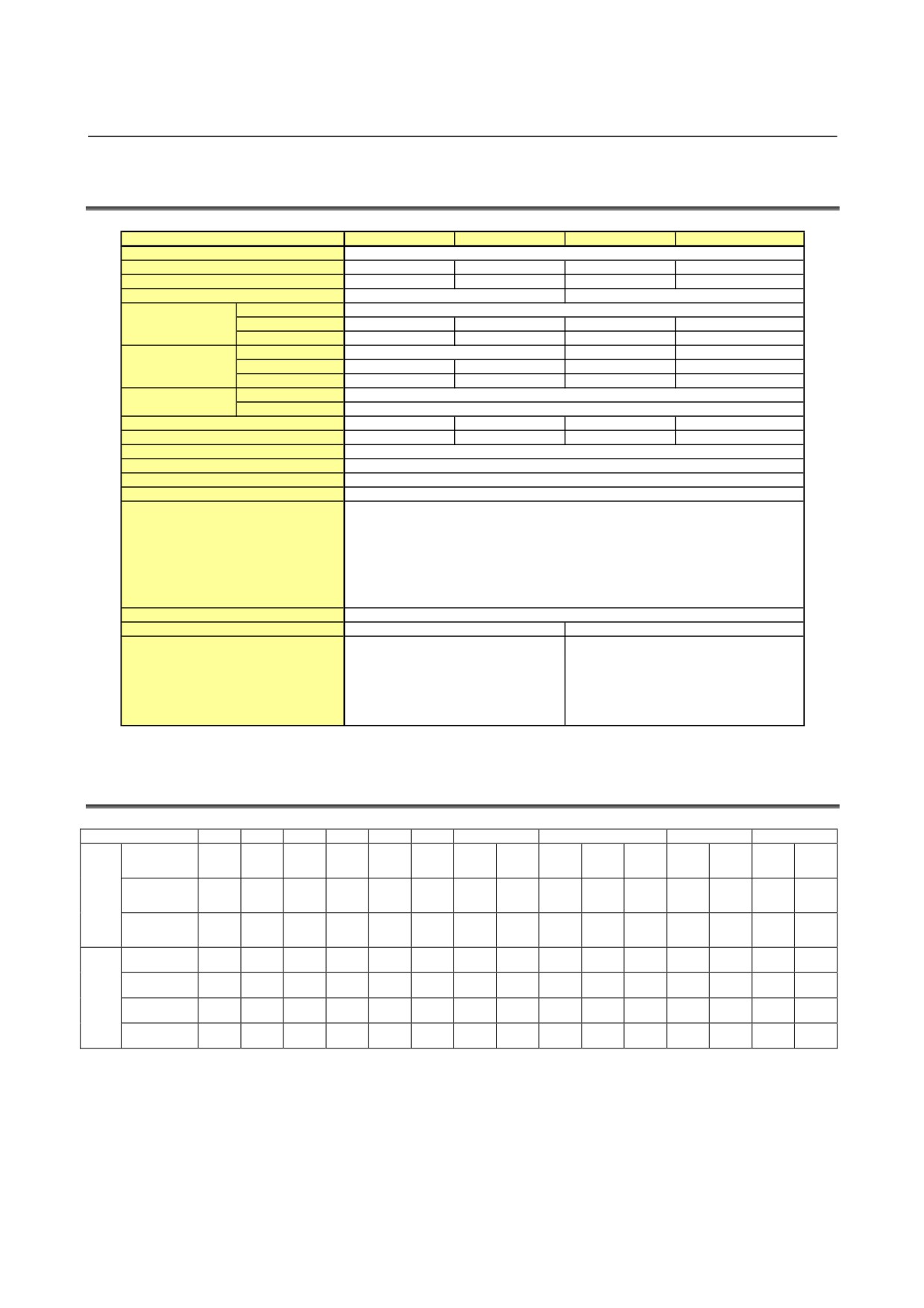
SPECIFICATIONS
Item
SVM-4i
SVM-20i
SVM1-40i
SVM1-80i
Interface
FSSB
Unit drawing No.
A06B-6130-H001
A06B-6130-H002
A06B-6130-H003
A06B-6130-H004
Power PC board drawing No.
A20B-2101-0090
A20B-2101-0091
A16B-3200-0512
A16B-3200-0513
Control PC board drawing No.
A20B-2101-0050
A20B-2101-0051
Input voltage
200-240 VAC (+10%,-15%)
50 / 60 Hz
Main power supply
Input current (50 Hz)
0.5 Arms
8.0 Arms
14.0Arms
19.0Arms
3-phase input
Power supply rating
0.2 kVA
2.8 kVA
4.7kVA
6.5kVA
Input voltage
220-240 VAC (+10%,-15%) 50/60 Hz
-
-
Main power supply
Input current (50 Hz)
1.1Arms
8.0Arms
-
-
Single-phase input
Power supply rating
0.3 kVA
1.9 kVA
-
-
Input voltage
24 VDC (+10%, -10%)
Control power supply
Input current
0.9 Arms
Rated output current
0.9Arms
6.8Arms
13Arms
18.5Arms
Maximum output current
4Ap
20 Ap
40 Ap
80 Ap
Servo HRV control
HRV2, HRV3
Control method
Sine Wave PWM Control with Transistor Bridges
Dynamic brake circuit
Included
Output frequency range
0-334Hz
- High Current
- IPM Abnormal
- High Voltage of DC Link
- Low Voltage of DC Link
Protection function
- Overheat of Discharge Resistor
- Low Voltage of Control Power Supply
- FSSB Communication Error
- Locked Fan Motor
Ambient temperature range
0°C to +55°C
Weight
1.2kg
3.9kg
Separated regenerative resistor
Built-in regenerative resistor
(30 Ω, 20W/100W)
(16 Ω, 50 W, no-wind condition)
(16 Ω, 130 W, wind velocity of 2m/s)
Remarks
Separated regenerative resistor
Separate AC line filter
(16 Ω, 200 W to 1200W)
Separate battery
Separate AC line filter
Separate battery
3.2
APPLICABLE MOTORS
0.2
0.3
0.4
0.5
1
2
4
8
12
22
α1/
α2/
α4/
α8/
α12/
α22/
αi
5000i
5000i
4000i
3000i
3000i
3000i
(20A)
(20A)
(40A)
(40A)
(80A)
(80A)
α2/
α4/
α8/
α12/
Motor
αis
5000is
5000is
4000is
4000is
(20A)
(20A)
(80A)
(80A)
β0.2/
β0.3/
β0.4/
β0.5/
β1/
β2/
β4/
β8/
β12/
β22/
βis
5000is
5000is
5000is
5000is
5000is
4000is
4000is
3000is
3000is
2000is
(4A)
(4A)
(20A)
(20A)
(20A)
(20A)
(20A)
(20A)
(40A)
(40A)
SVM1-4i
O
O
SVM1-20i
O
O
O
O
O
O
SVM1
SVM1-40i
O
O
O
O
SVM1-80i
O
O
O
- 8 -
B-65322EN/02
SVM
3.SPECIFICATIONS
3.3
SELECTING CIRCUIT BREAKER, MAGNETIC
CONTACTOR, AND AC LINE FILTER
3.3.1
Selecting Circuit Breaker
Select a circuit breaker based on the continuous current ratings of the
individual motors listed below. When connecting more than one
amplifier, determine the rating of the circuit breaker based on the sum
of the continuous current ratings of the motors.
When the motor accelerates or decelerates rapidly, current about three
times as high as the continuous current rating may flow for
approximately three seconds. So, select a circuit breaker that does
not trip under such current flow conditions.
WARNING
Because of a possibility of cable burning, consider
protection co-ordination of the cables between the
circuit breaker output and the input of each
amplifier and the selected circuit breaker.
Table Input current for continuous output rating
Continuous current
Continuous current
Power supply rating
Power supply rating
rating with 3-phase
rating with
with single-phase
with 3-phase input
Servo motor
input
single-phase input
input
[kVA]
[Arms]
[Arms]
[kVA]
(Reference)
(Reference)
(Reference)
(Reference)
β0.2/5000is
0.2
0.08
0.5
0.12
β0.3/5000is
0.5
0.15
1.1
0.25
β0.4/5000is
0.6
0.20
1.4
0.32
β0.5/5000is
0.9
0.31
2.2
0.49
β1/5000is
1.8
0.62
4.3
1.0
β2/4000is
2.2
0.77
5.4
1.2
β4/4000is
3.3
1.2
8.1
1.9
β8/3000is
5.4
1.9
9.7
2.2
β12/3000is
8.0
2.8
-
-
β22/2000is
11.1
3.9
-
-
α1/5000i
2.2
0.77
5.4
1.2
α2/5000i
3.3
1.2
8.1
1.9
α4/4000i
6.2
2.2
-
-
α8/3000i
7.1
2.5
-
-
α12/3000i
13.4
4.6
-
-
α22/3000i
17.8
6.2
-
-
α2/5000is
3.3
1.2
8.1
1.9
α4/5000is
4.5
1.5
9.7
2.2
α8/4000is
11.1
3.9
-
-
α12/4000is
12.0
4.2
-
-
- 9 -
3.SPECIFICATIONS
SVM
B-65322EN/02
3.3.2
Selecting Magnetic Contactor
Select a magnetic contactor according to the table, "Input current for
continuous output rating". When connecting more than one amplifier,
make a selection based on the sum of the continuous current ratings of
the motors.
Manufacturer's specification (Fuji Electric)
Rated current
SC-5-1
19A
SC-N1
26A
WARNING
For details, refer to the brochure supplied by Fuji
Electric Co., Ltd.
3.3.3
AC Line Filter
Select an AC line filter according to the table, "Input current for
continuous output rating". When connecting more than one amplifier,
make a selection based on the sum of the continuous current ratings of
the motors.
To reduce the influence of high frequency noise on the power supply,
be sure to use an AC line filter or EMC noise filter. The LF series
manufactured by TOKIN is available as the EMC noise filter.
AC line filter
Continuous
Continuous
Heat
current rating
output rating
dissipation
A81L-0001-0083#3C
24A
5.4kW or less
20W
A81L-0001-0101#C
44A
10.5kW or less
70W
A81L-0001-0102
100A
23kW or more
50W
WARNING
The AC line filter is different from the AC reactor.
Neither substitution between them nor use of one
of them for both purposes is allowed.
- 10 -
B-65322EN/02
SVM
3.SPECIFICATIONS
3.4
COOLING FAM MOTORS
3.4.1
Models Requiring Cooling Fan motors
The combinations listed below require cooling fan motors.
Ordering number
Amplifier
Combined motor
A06B-6134-K002
SVM1-80i
General 80-A class motors
SVM1-20i
α4/5000is
Running on 3-phase
β8/3000is
200-240 VAC power
α2/5000i
A06B-6134-K003
SVM1-20i
α2/5000is
Running on 1-phase
α4/5000is
220-240 VAC power
β4/4000is
β8/3000is
3.4.2
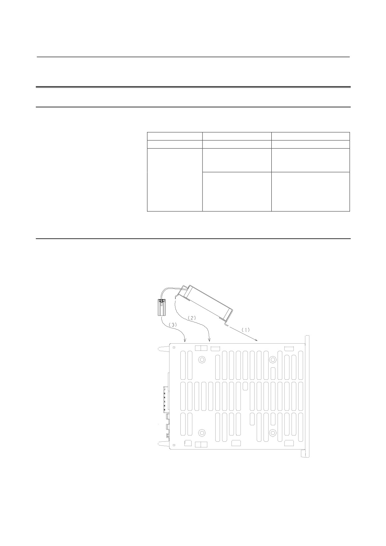
Installing a Separate Cooling Fan motor
When using one of the above combinations that require a cooling fan
motor, install an optionally available fan motor in the order (1), (2),
and (3) as illustrated below.
- 11 -