FANUC AC Servo Amplifiers βi Series. Description Manual (B-65322EN/02) - page 4
9.TOTAL CONNECTION DIAGRAM
SVM
B-65322EN/02
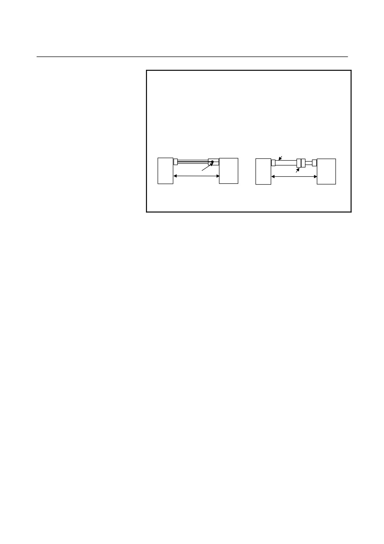
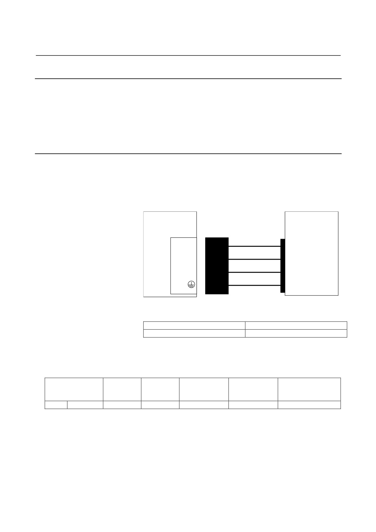
NOTE
1 In case that the cable is prepared by MTB, total resistance
of 5V and 0V must be less than 2Ω.
2 Pulsecoder side connector can accept maximum 0.5mm2
(wire construction 20/0.18 or 104/0.08, insulation outer
diameter φ1.5 or less) wire and sheath diameter is φ5.7 to
φ8.0. In case of using thicker wire or cable, take measures
described below.
[Case 1] Cable conductor exceeds 0.5mm2 .
[Case 2] Sheath diameter of exceeds φ8.
Servo motor
SVM
SVM
Cable thicker than φ8
Servo motor
Soldering or crimping
Connector
The total resistance (round
The total resistance (round
trip) of 5 V and 0 V must be
trip) of 5 V and 0 V must be
less than 2Ω.
less than 2Ω.
3 In case of incremental Pulsecoder, 6V is not necessary to
be connected.
• Crimp tool specification
A06B-6114-K201/JN1S : For 0.3 mm2
A06B-6114-K201/JN1L : For 0.18 mm2 or 0.5 mm2
• Connector kit specification
A06B-6114-K204/S : Straight plug (including a contact)
A06B-6114-K204/E : Elbow plug (including a contact)
•
Recommended cable
A66L-0001-0460 : Flexible cable 28 m or less long
A66L-0001-0462 : Flexible cable 50 m or less long
A66L-0001-0481 : Fixed cable 28m or less long
A66L-0001-0491 : Fixed cable 50m or less long
- 74 -
B-65322EN/02
SVM
9.TOTAL CONNECTION DIAGRAM
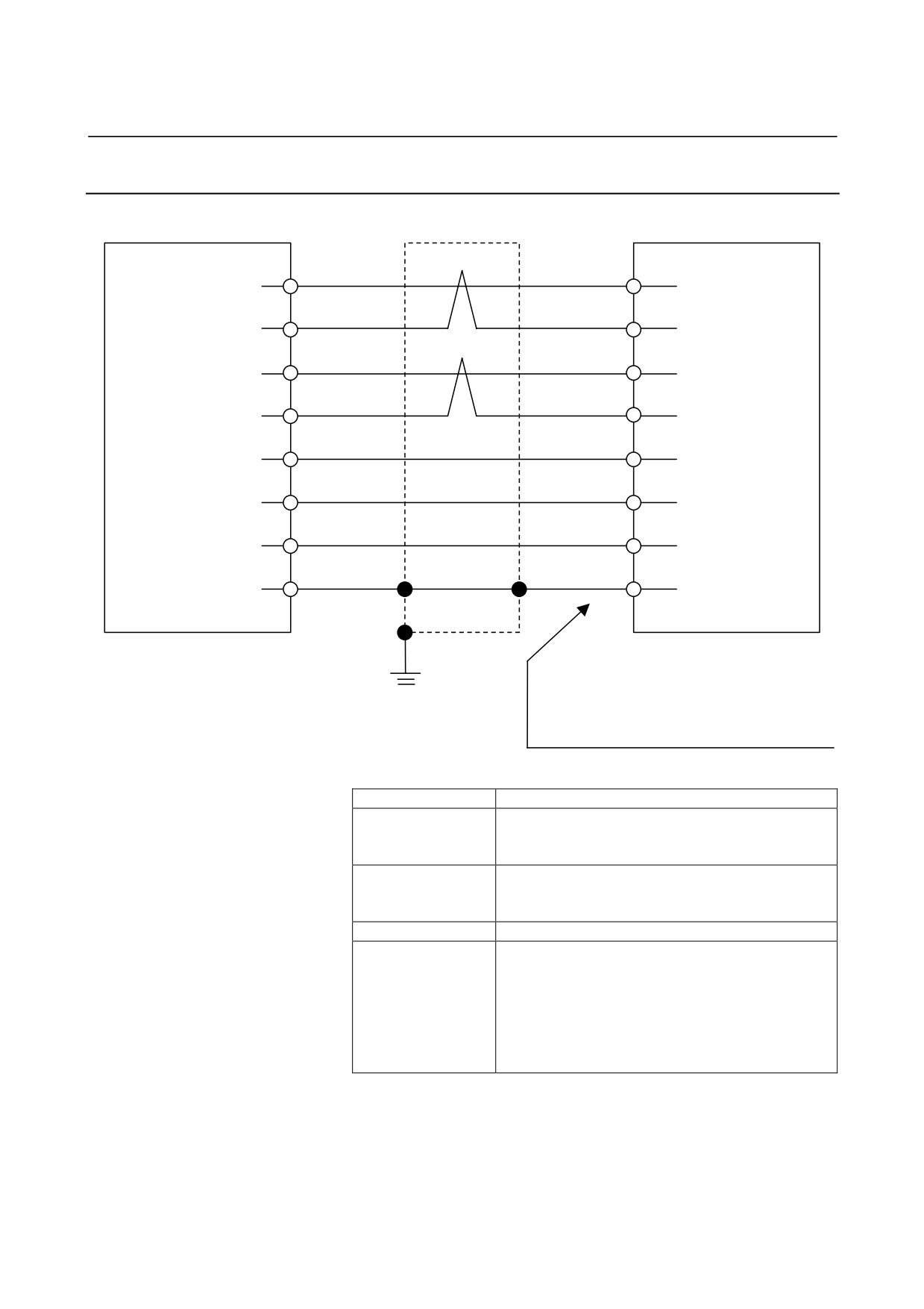
9.2.4.2 Servo motor βis series (β0.2/5000is, β0.3/5000is)
Shield
SVM
Servo motor
(1)
SD
(A4)
(2)
*SD
(B4)
(5)
REQ
(A3)
(6)
*REQ
(B3)
(9, 20)
5V
(A2, B2)
(12, 14)
0V
(A1, B1)
(7)
6V
(A5)
(16)
Drain wire
FG
(B6)
20-pin half-pitch connector
Housing : 1-1318118-6 (D-2100D 12 poles)
Contact : 1318107-1 (D-2 receptacle M)
Grounding
Contact : 1318108-1 (D-2 receptacle S)
plate
Manufacture : Tyco Electronics AMP
Using cable conductor
Cable length
20 m or less
0.5 mm2 (AWG21) × 5
5V, 0V, 6V
Wire construction 20/0.18
Insulation outer diameter φ0.88 to φ1.5
0.18mm2(AWG25) or more Twisted-pair wire
SD, *SD, REQ,
Wire construction 7/0.18
*REQ
Insulation outer diameter φ0.88 to φ1.5
Drain wire
0.15mm2 or more
0.5mm2 × 5 + 0.18mm2 × two-pair
(For a fixed cable)
Hitachi Cable, Ltd. : UL20276-SB (0)
Recommended wire
5X21AWG+2PX25AWG
(For a flexible cable)
Hitachi Cable, Ltd. : UL20276-SB (FLEX)
5X20AWG+2PX25AWG
- 75 -
9.TOTAL CONNECTION DIAGRAM
SVM
B-65322EN/02
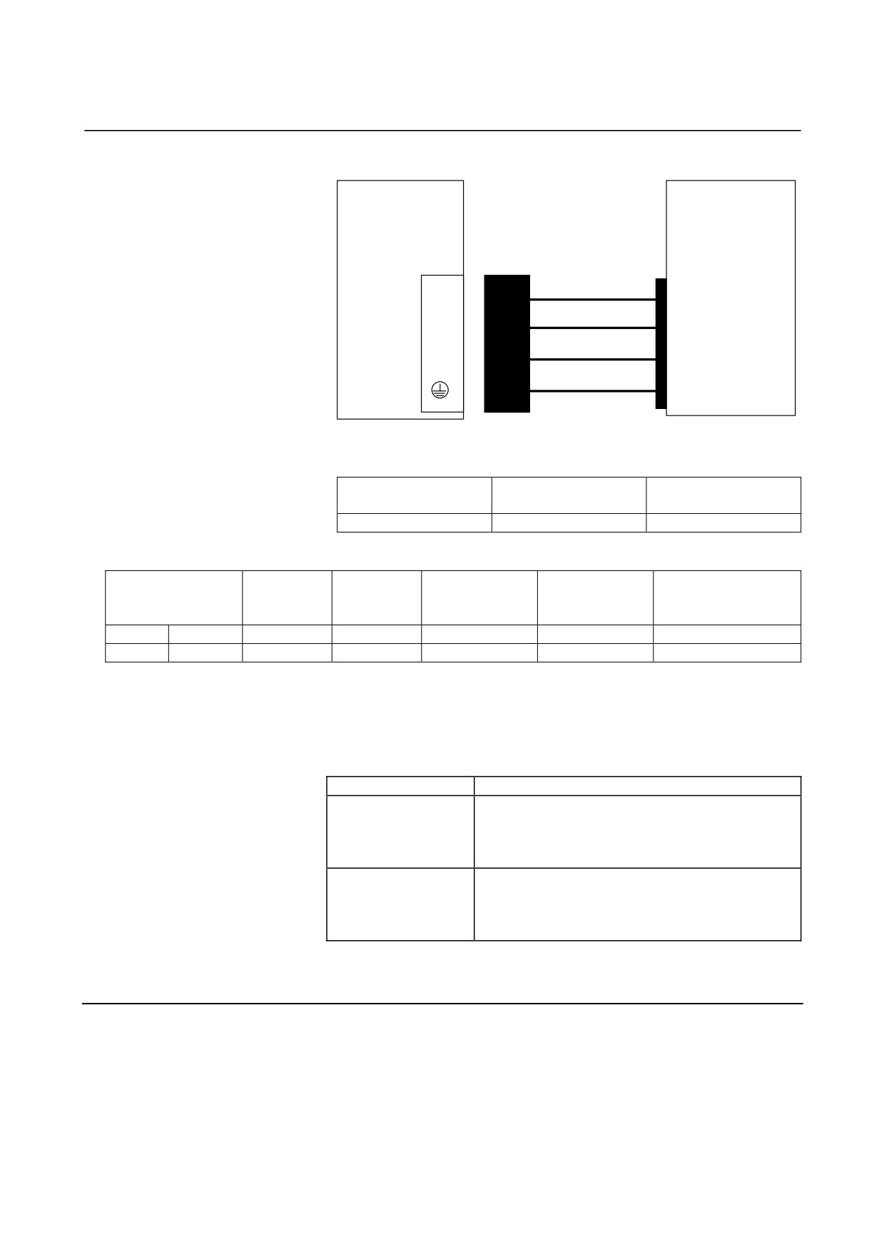
NOTE
1 The ground plate to which the shield is connected
must be placed as close as possible to the servo
amplifier so that distance between the ground plate
and the servo amplifier becomes shortest.
2 In case that the cable is prepared by the user, the
total resistance (round trip) of 5 V and 0 V must be
less than 0.8 Ω.
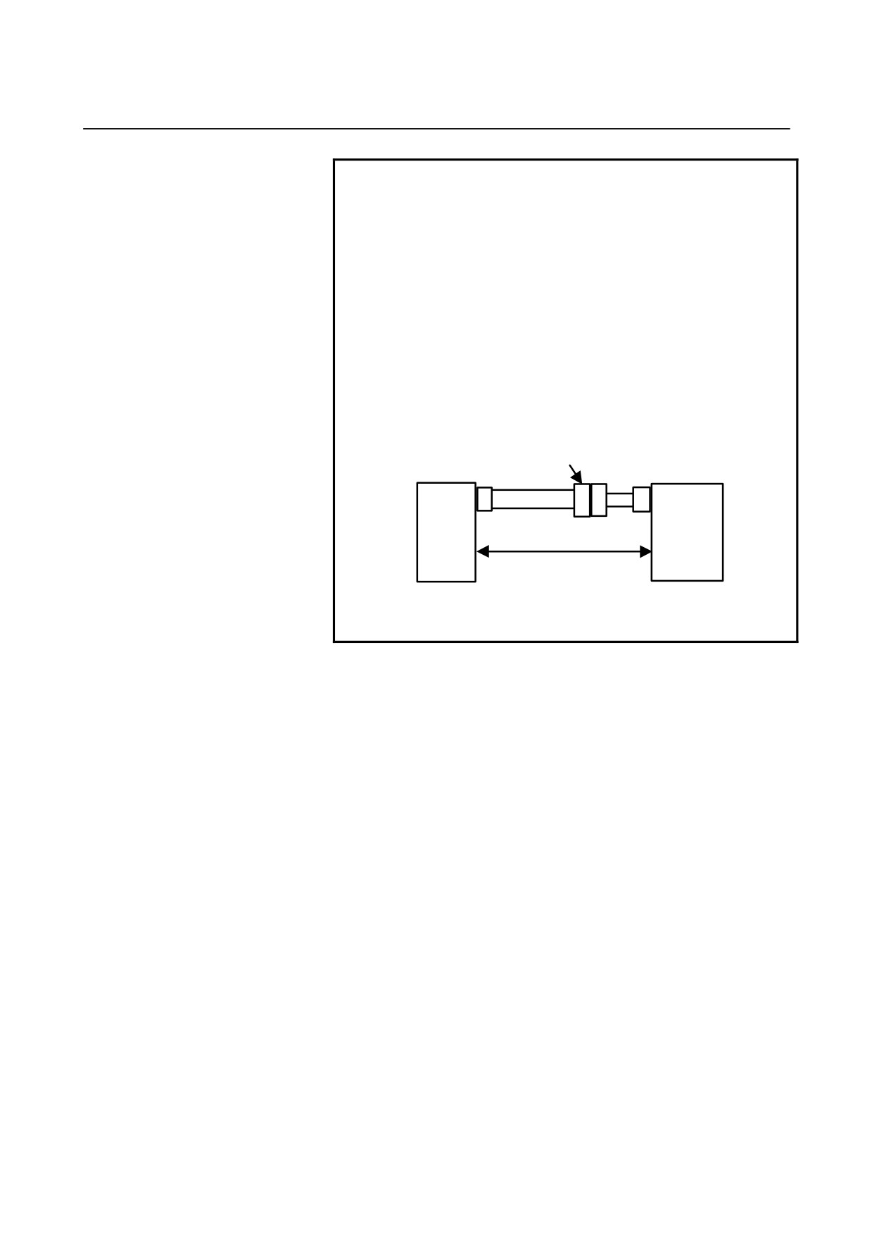
3 The maximum applicable wire diameter of the cable
connector on the motor side is 0.5 mm2 (when
crimping tool 1463475-1 is used) or 0.85 mm2
(when crimping tool 1276654-1 is used).In case of
using thicker wire or cable, take measures
described below.
Connector
Servo
Servo motor
amplifier
The total resistance (round
trip) of 5 V and 0 V must be
less than 0.8Ω.
4 In case of incremental Pulsecoder, 6 V is not
necessary to be connected.
- 76 -
B-65322EN/02
SVM
9.TOTAL CONNECTION DIAGRAM
9.2.5
Details of Cable K2
The following items related to servo amplifier
input
cables
are
explained below in the stated order.
(1) Details of connectors
(2) Selecting input cables (general)
(3) Details of input cables
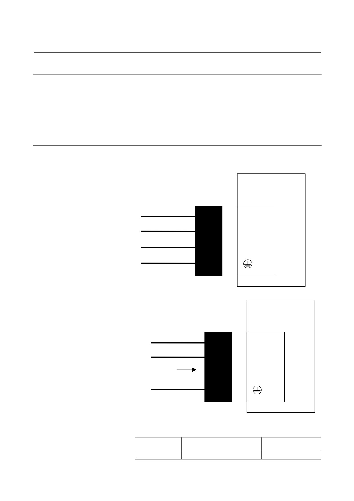
9.2.5.1
Details of connectors
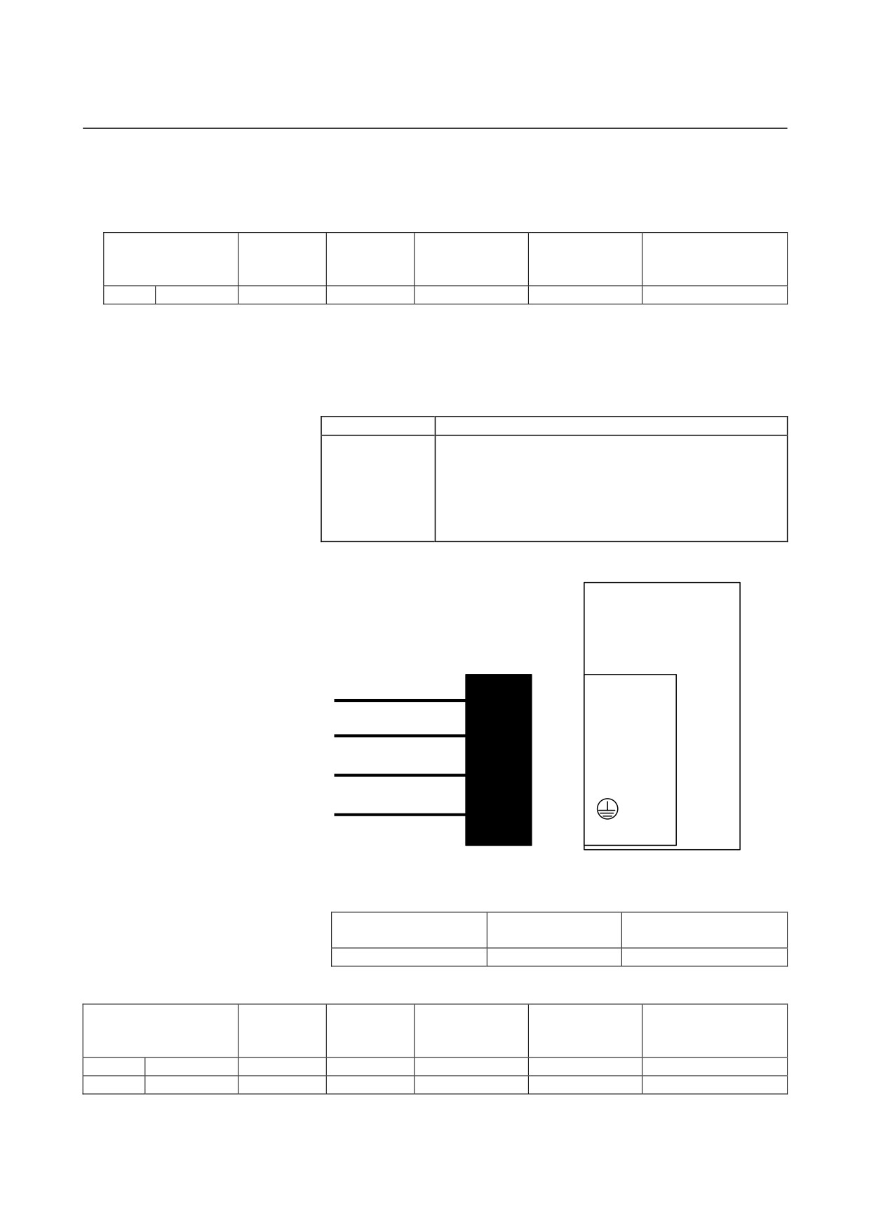
(a) SVM1-4i, SVM1-20i
Three-phase input
βi SVM
Receptacle housing
CZ7
B1
L1
A1
L2
B2
L3
A2
Single-phase input
βi SVM
Receptacle housing
CZ7
B1
L1
A1
L2
Leave open
L3
A2
[Receptacle housing]
Use the following receptacle housing.
Manufacturer-d
Specification of the key
Manufacture
efined model
175363-3
Incorrect-insertion prevent key
Tyco Electronics AMP
- 77 -
9.TOTAL CONNECTION DIAGRAM
SVM
B-65322EN/02
[Receptacle contact]
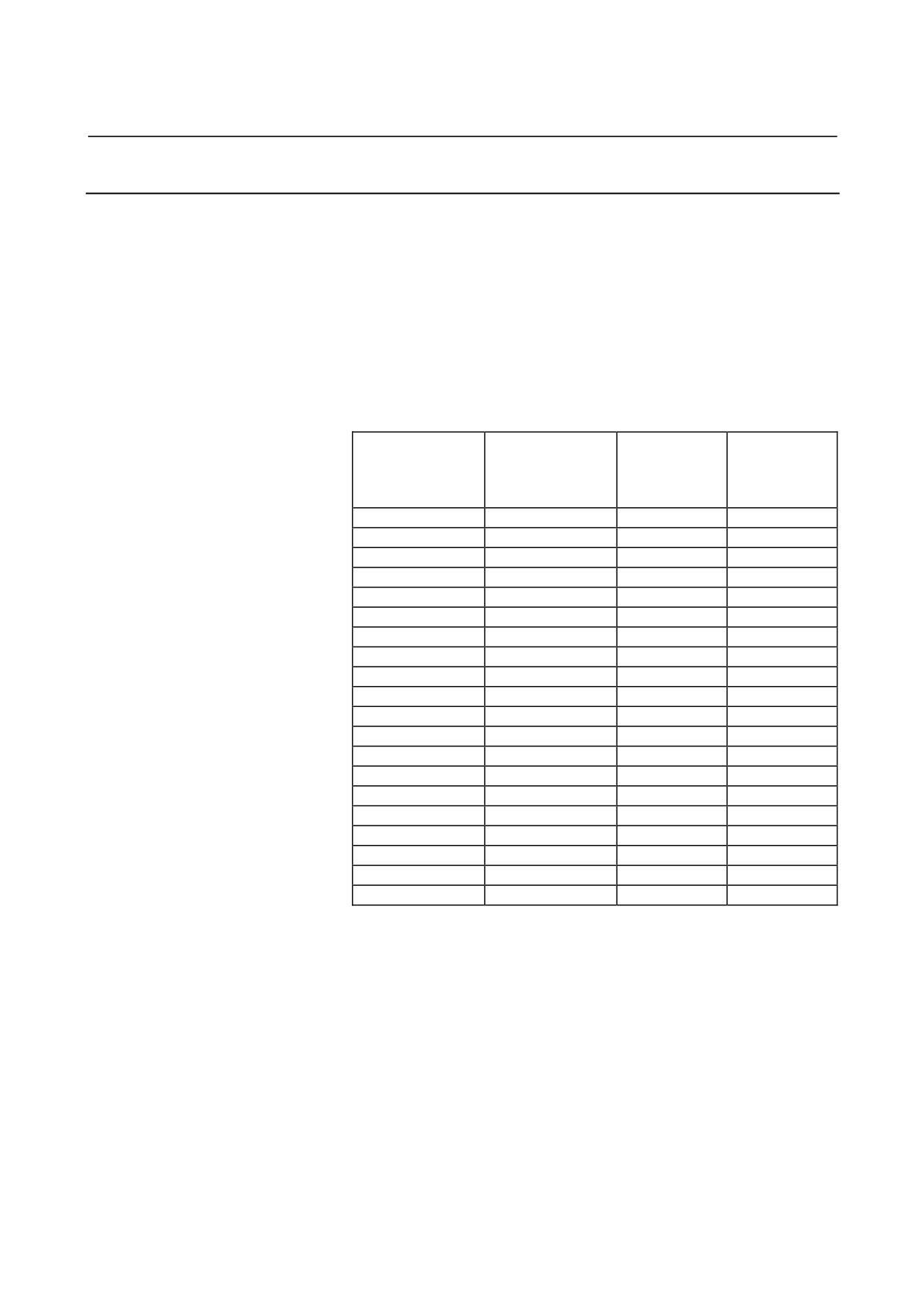
Two receptacle contact types are available, so as to support
different conductor diameters. Be sure to select the
receptacle contact that matches the servo axis you use.
Conductor
Conductor
Rectangle contact
Insulation outer
Manual tool
size
size
Manufacture
model number
diameter (mm)
model number
(mm2)
AWG
L size
1-175218-2
0.5- 1.25
20/18/16
1.8-2.8
91558-1
Tyco Electronics AMP
[Connector and tool ordering information]
Connectors (including housings and contacts) and tools can
be purchased directly from Tyco Electronics AMP. They
can be ordered as options also from FANUC as listed
below.
Ordering number
Description
Housing : Incorrect-insertion prevent key 175363-3
(1pcs.)
Incorrect-insertion prevent key 1318095-2 (1pcs.)
Contact : L size
1-175218-2
(10pcs.)
A06B-6130-K200
Applicable wire diameter:
0.5-1.25mm2, AWG20/18/16
Applicable tool: 91558-1 (not included in this kit)
(b) SVM1-40i, SVM1-80i
Receptacle housing
βi SVM
CZ4
B1
L1
A1
L2
B2
L3
A2
[Receptacle housing]
Use the following receptacle housing.
Manufacturer-defined
Specification of
Manufacture
model
the key
1-917807-2
XX
Tyco Electronics AMP
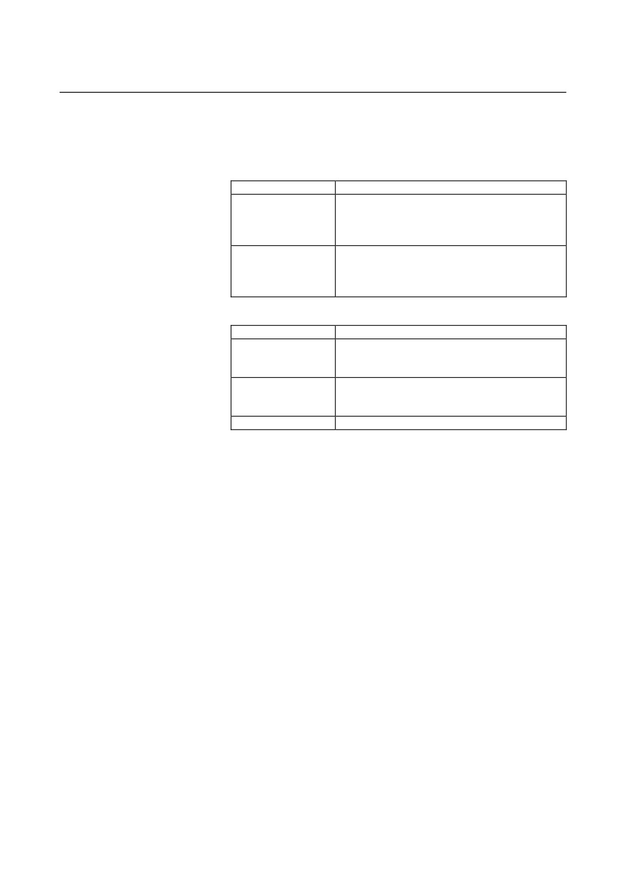
[Receptacle contact]
Conductor
Conductor
Rectangle contact
Insulation outer
Manual tool
size
size
Manufacture
model number
diameter (mm)
model number
(mm2)
AWG
S size
316040-6
1.25
- 2.20
16/14
3.0-3.8
234170-1
Tyco Electronics AMP
M size
316041-6
3.50
- 5.50
12/10
4.0-5.2
234171-1
Tyco Electronics AMP
- 78 -
B-65322EN/02
SVM
9.TOTAL CONNECTION DIAGRAM
[Connector and tool ordering information]
Connectors (including housings and contacts) and tools can
be purchased directly from Tyco Electronics AMP. They
can be ordered as options also from FANUC as listed
below.
Ordering number
Description
Housing : XX key
1-917807-2
(1pcs.)
Contact : S size
316040-6
(4pcs.)
A06B-6110-K200#XXS
Applicable wire diameter : 1.25-2.20mm2, AWG16/14
Applicable tool: 234170-1 (not included in this kit)
Housing : XX key
1-917807-2
(1pcs.)
Contact : M size
316041-6
(4pcs.)
A06B-6110-K200#XXM
Applicable wire diameter : 3.50-5.50mm2, AWG12/10
Applicable tool : 234171-1 (not included in this kit)
[Crimping tool]
Ordering number
Description
Applicable tool : 234170-1
A06B-6110-K220#D5S
Contact : S size
316040-6
Applicable wire diameter : 1.25-2.2mm2, AWG16/14
Tool : 234171-1
A06B-6110-K220#D5M
Contact : M size
316041-6
Applicable wire diameter: 3.50-5.50mm2, AWG12/10
A06B-6110-K220#D5R
Extractor : 409158-1
- 79 -
9.TOTAL CONNECTION DIAGRAM
SVM
B-65322EN/02
9.2.5.2 Selecting cables (general)
Select the cable specification by considering the following conditions
for use:
(1) Motor current rating or current needed in use on a real machine
(2) Cable type (heat resistance temperature, etc.)
(3) Environment in which the cable is installed (operating ambient
temperature, etc.)
(4) Certification for CE marking (compliance with various safety
standards and EMC standard)
Examples of selecting a heavy-duty power cable are shown below.
Fully check the cable specifications based on the actual use conditions
and use an example below.
The cable diameters are determined based on JCS No. 168 D (1980),
"Allowable Currents for Power Cables (1)."
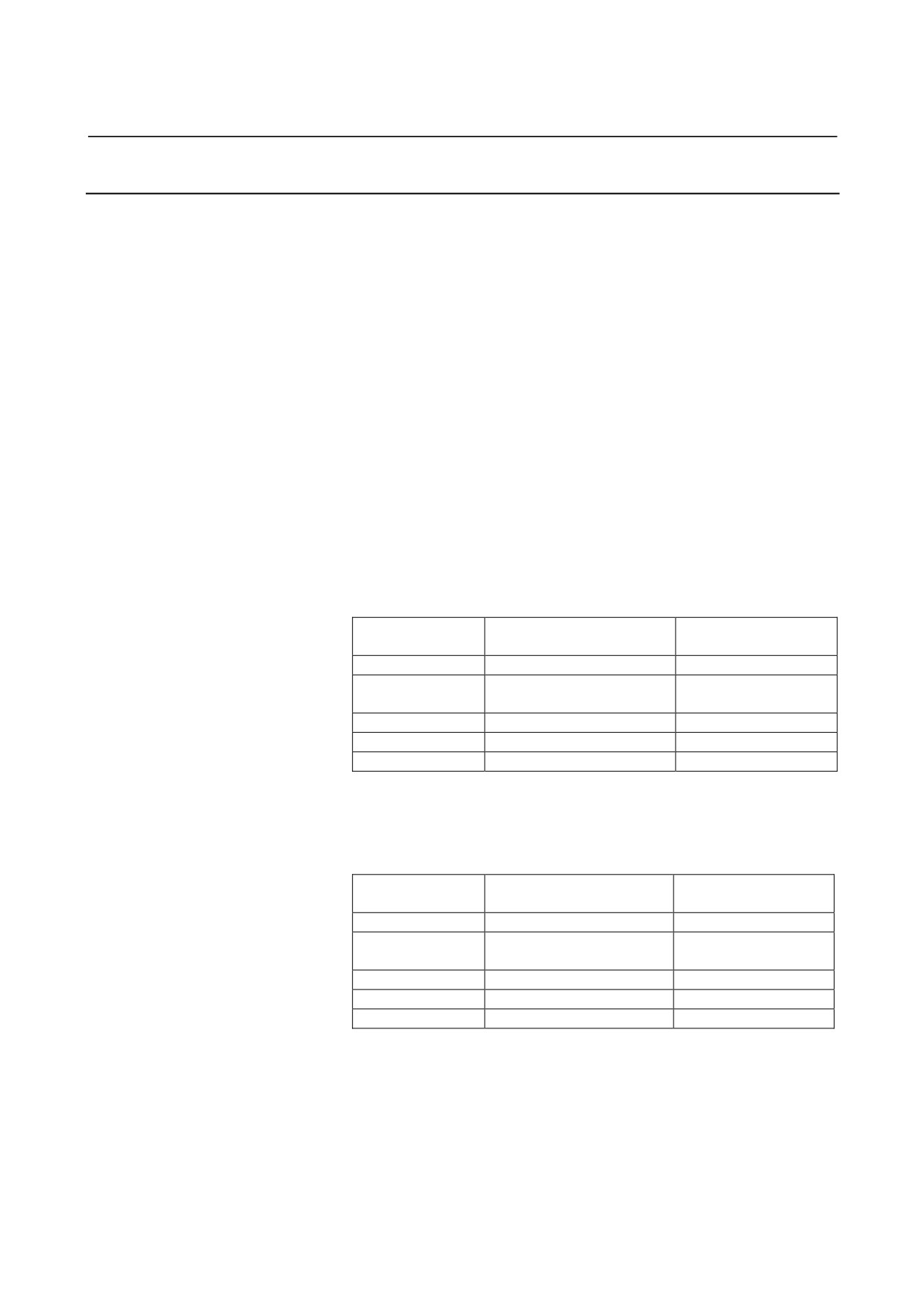
Selection example of power line (reference)
[Selection example 1]
• Heavy-duty power cable specification :
Maximum allowable conductor temperature 60°C
• Environment temperature : 30°C
Cable diameter
Allowable current value
Receptacle contact
[mm2]
[Arms]
specification
0.75
Less than 11
L size
1-175218-2
L size
1-175218-2
1.25
Less than 15
S size
316040-6
2
Less than 19
S size
316040-6
3.5
Less than 27
M size
316041-6
5.5
Less than 35
M size
316041-6
[Selection example 2]
• Heavy-duty power cable specification :
Maximum allowable conductor temperature 80°C
• Environment temperature : 55°C
Cable diameter
Allowable current value
Receptacle contact
[mm2]
[Arms]
specification
0.75
Less than 9.2
L size
1-175218-2
L size
1-175218-2
1.25
Less than 12.7
S size
316040-6
2
Less than 16.3
S size
316040-6
3.5
Less than 23.4
M size
316041-6
5.5
Less than 31.2
M size
316041-6
- 80 -
B-65322EN/02
SVM
9.TOTAL CONNECTION DIAGRAM
9.2.5.3
Details of input cables
Select cables by taking the following conditions for use into account.
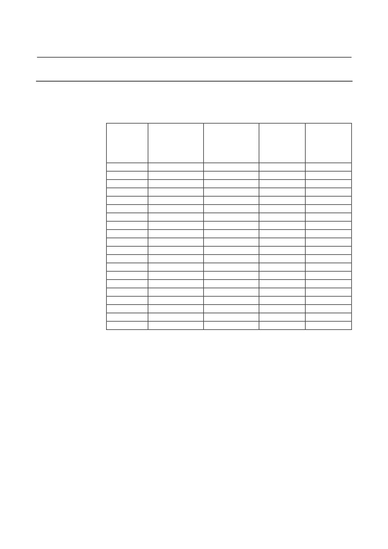
[Example combinations of input cables for servo motors running with
continuous-rating output (reference only)]
Continuous
Continuous
[Example 1.]
[Example 2.]
current rating for
current rating for
Cable wire
Cable wire
Servo motor
three-phase input
single-phase input
diameter
diameter
[Arms]
[Arms]
[mm2]
[mm2]
(reference only)
(reference only)
β0.2/5000is
0.2
0.5
0.75
(0.75)
0.75
(0.75)
β0.3/5000is
0.5
1.1
0.75
(0.75)
0.75
(0.75)
β0.4/5000is
0.7
1.4
0.75
(0.75)
0.75
(0.75)
β0.5/5000is
1.1
2.2
0.75
(0.75)
0.75
(0.75)
β1/5000is
2.1
4.3
0.75
(0.75)
0.75
(0.75)
β2/4000is
2.6
5.4
0.75
(0.75)
0.75
(0.75)
β4/4000is
3.9
8.1
0.75
(0.75)
0.75
(0.75)
β8/3000is
6.3
9.7
0.75
(0.75)
0.75
(1.25)
β12/3000is
9.4
-
0.75
1.25
β22/2000is
13.1
-
1.25
2
α1/5000i
2.6
5.4
0.75
(0.75)
0.75
(0.75)
α2/5000i
3.9
8.1
0.75
(0.75)
0.75
(0.75)
α4/4000i
7.3
-
0.75
0.75
α8/3000i
8.4
-
0.75
0.75
α12/3000i
15.7
-
2
2
α22/3000i
21.0
-
3.5
3.5
α2/5000is
3.9
8.1
0.75
(0.75)
0.75
(0.75)
α4/5000is
5.2
9.7
0.75
(0.75)
0.75
(1.25)
α8/4000is
13.1
-
1.25
2
α12/4000is
14.2
-
1.25
2
- 81 -
9.TOTAL CONNECTION DIAGRAM
SVM
B-65322EN/02
9.2.6
Details of Cable K3
The following items related to servo motor/amplifier power cables are
explained below in the stated order.
(1) Details of connectors
(2) Selecting power cables (general)
(3) Power cable for servo motor
9.2.6.1
Details of connectors
The D-3000 and -5000 connector series
(manufactured by Tyco
Electronics AMP.) are used for power cable connection in the βi series.
The specifications of a receptacle housing and contact vary depending
on the model for which they are used as stated below.
(a) SVM1-4i, SVM1-20i
βi SVM
Motor
Receptacle housing
CZ7
B1
U
U
A1
V
V
B2
W
W
A2
GND(Body)
[Receptacle housing]
Use the following receptacle housing.
Manufacturer-defined model
Manufacture
1318095-2
Tyco Electronics AMP
[Receptacle contact]
Two receptacle contact types are available, so as to support
different conductor diameters. Be sure to select the
receptacle contact that matches the servo axis you use.
Conductor
Conductor
Rectangle contact
Insulation outer
Manual tool
size
size
Manufacture
model number
diameter (mm)
model number
(mm2)
AWG
L size
1-175218-2
0.5-1.25
20/18/16
1.8-2.8
91558-1
Tyco Electronics AMP
[Connector and tool ordering information]
Connectors (including housings and contacts) and tools can
be purchased directly from Tyco Electronics AMP. They
can be ordered as options also from FANUC as listed
below.
See Subsection 5.2.4 “Details of Cable K2.”
- 82 -
B-65322EN/02
SVM
9.TOTAL CONNECTION DIAGRAM
(b) SVM1-40i, SVM1-80i
Motor
βi SVM
Receptacle housing
CZ5
B1
U
U
A1
V
V
B2
W
W
A2
GND(Body)
[Receptacle housing]
Use the following receptacle housing.
Manufacturer-defined
Specification of the
Manufacture
model
key
2-917807-2
YY
Tyco Electronics AMP
[Receptacle contact]
Conductor
Conductor
Rectangle contact
Insulation outer
Manual tool
size
size
Manufacture
model number
diameter (mm)
model number
(mm2)
AWG
S size
316040-6
1.25-2.2
16/14
3.0-3.8
234170-1
Tyco Electronics AMP
M size
316041-6
3.5-5.5
12/10
4.0-5.2
234171-1
Tyco Electronics AMP
[Connector and tool ordering information]
Connectors (including housings and contacts) and tools can
be purchased directly from Tyco Electronics AMP. They
can be ordered as options also from FANUC as listed
below.
Ordering number
Description
Housing : YY key
2-917807-2
(1pcs.)
Contact : S size
316040-6
(4pcs.)
A06B-6110-K202#YYS
Applicable wire diameter : 1.25-2.20mm2, AWG16/14
Applicable tool : 234170-1 (not included in this kit)
Housing : YY key
2-917807-2
(1pcs.)
Contact : M size
316041-6
(4pcs.)
A06B-6110-K202#YYM
Applicable wire diameter : 3.50-5.50mm2, AWG12/10
Applicable tool : 234171-1 (not included in this kit)
9.2.6.2 Details of cables (general)
See Subsection 5.2.4 “Details of Cable K2.”
- 83 -
9.TOTAL CONNECTION DIAGRAM
SVM
B-65322EN/02
9.2.6.3
Power cable for servo motor
A servo motor power cable assembly consists of:
(a) Power cable
(b) Motor-side connector
(a) Power cable
Examples of combining a servo motor and power cable are
described below according to Subsection
5.2.4.2,
“Selecting
cables (general).”
[Example combination of servo motor and
power cable
(reference only)]
Continuous
[Example 1.]
[Example 2.]
current rating
Cable wire
Cable wire
Servo motor
[Arms]
diameter
diameter
(reference only)
[mm2]
[mm2]
β0.2/5000is
0.84
0.75
0.75
β0.3/5000is
0.84
0.75
0.75
β0.4/5000is
3.5
0.75
0.75
β0.5/5000is
3.0
0.75
0.75
β1/5000is
2.7
0.75
0.75
β2/4000is
3.2
0.75
0.75
β4/4000is
4.7
0.75
0.75
β8/3000is
6.0
0.75
0.75
β12/3000is
10.2
0.75
1.25
β22/2000is
11.3
1.25
1.25
α1/5000i
2.7
0.75
0.75
α2/5000i
3.5
0.75
0.75
α4/4000i
7.7
0.75
0.75
α8/3000i
8.4
0.75
0.75
α12/3000i
18.1
2
3.5
α22/3000i
18.4
2
3.5
α2/5000is
3.3
0.75
0.75
α4/5000is
4.6
0.75
0.75
α8/4000is
11.1
1.25
1.25
α12/4000is
13.4
1.25
2
(b)
Motor-side connector
The specifications of a motor-side connector vary depending on
the motor model for which it is used.
Refer to “FANUC AC SERVO MOTOR βis series Descriptions”
(B-65302EN) for detailed descriptions about motor-side
connectors for the βis series servo motors.
Refer to
“FANUC AC SERVO MOTOR αis/αi series
Descriptions”
(B-65262EN) for detailed descriptions about
motor-side connectors for the αis/αi series servo motors.
- 84 -
B-65322EN/02
SVM
9.TOTAL CONNECTION DIAGRAM
9.2.7
Details of Cables K4 and K5
9.2.7.1 SVM1-4i and SVM1-20i
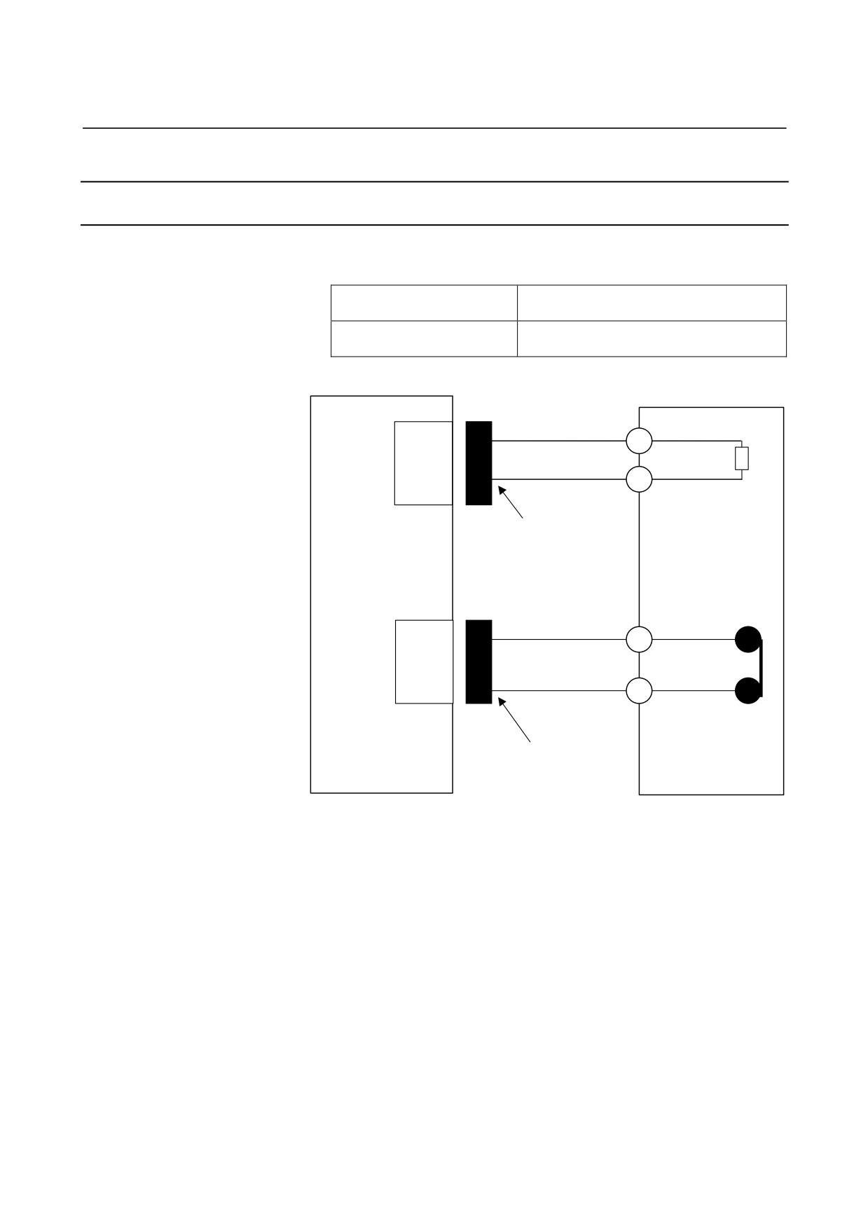
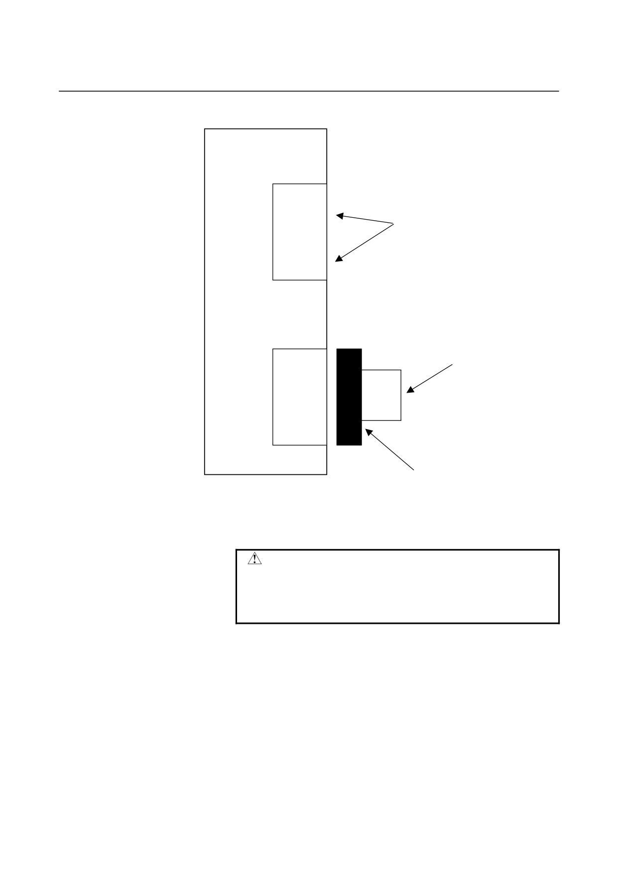
When a regenerative discharge resistor is used
The following regenerative discharge resistor models are available.
The following housing and contact are
A06B-6130-H401
connected to the resistor.
The following housing and contact are
A06B-6130-H402
connected to the resistor.
βi SVM
Regenerative
discharge resistor
CZ7
B1
DCP
DCP
A1
DCC
DCC
D-3000 series
Housing : 175362-3
Contact : 1-175218-2
Manufacture : Tyco Electronics AMP
Wire cross-sectional area :
0.50 to 1.25mm2
CXA20
1
TH1
2
TH2
βi SVM
D-2000 series
Housing : 1-1318120-3
Contact : 1318107-1
Manufacture : Tyco Electronics AMP
Wire cross-sectional area :
0.30 to 0.85mm2
For connection tools, see Subsection 9.2.3.
- 85 -
9.TOTAL CONNECTION DIAGRAM
SVM
B-65322EN/02
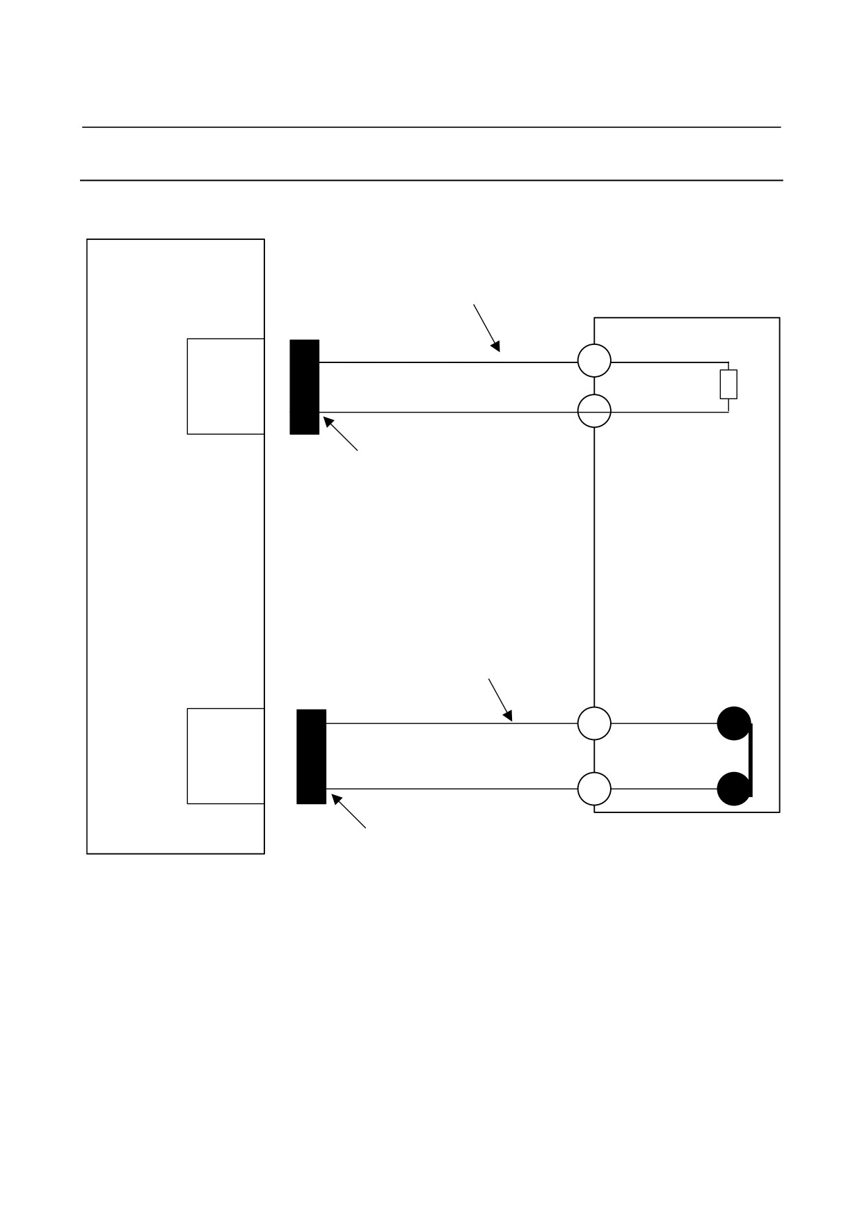
When no regenerative discharge resistor is used
βi SVM
CZ7
DCP
Keep these pins unconnected.
(Do not install a jumper between the pins.)
DCC
CXA20
1
Install a jumper between the pins.
2
D-2000 series
Housing : 1-1318120-3
Contact : 1318107-1
Manufacture : Tyco Electronics AMP
Wire cross-sectional area : 0.30 to 0.85mm2
For connection tools, see Subsection 9.2.3.
CAUTION
Do not connect the DCP and DCC pins to each
other.
It is recommended that the housing 1313182-2 be
inserted to prevent incorrect insertion.
- 86 -
B-65322EN/02
SVM
9.TOTAL CONNECTION DIAGRAM
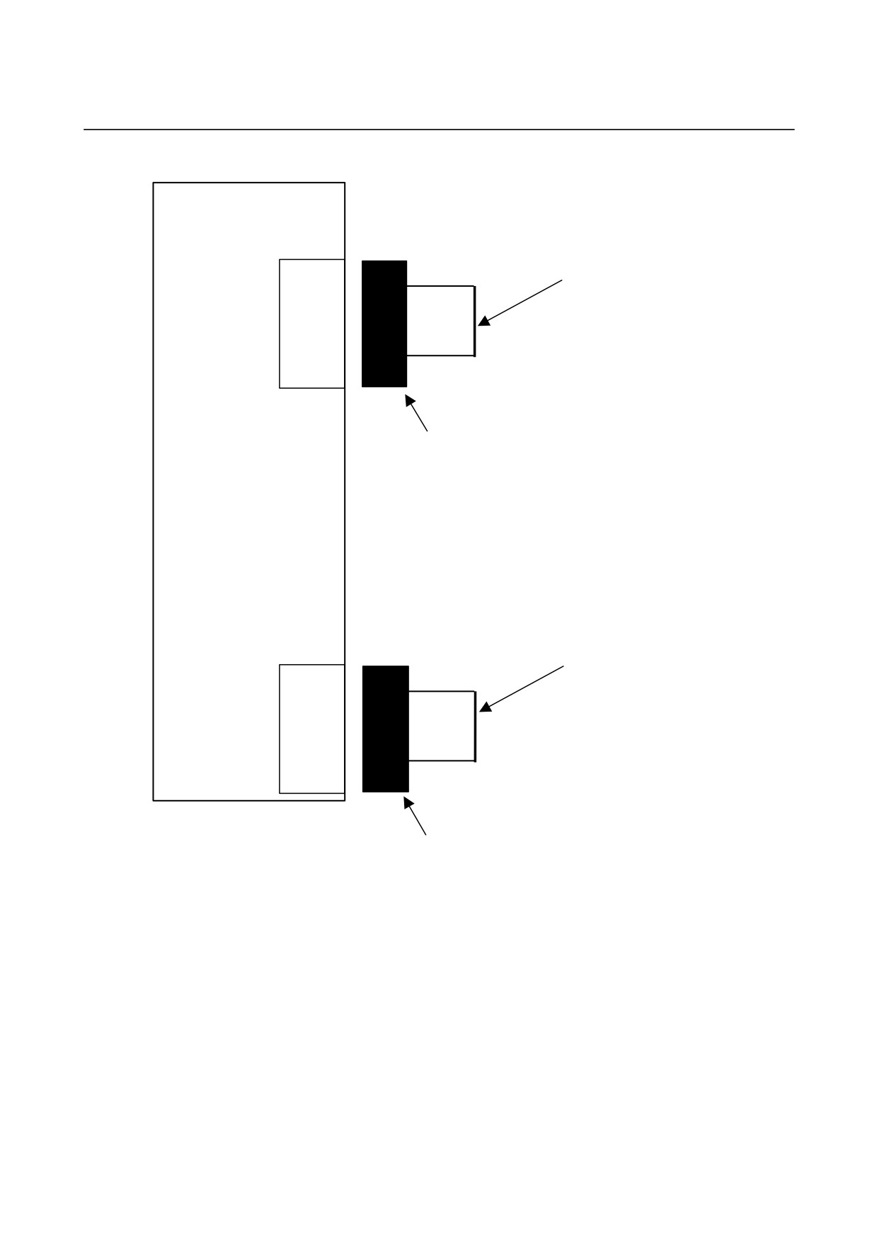
9.2.7.2 SVM1-40i and SVM1-80i
When a separated regenerative discharge resistor is used
βi SVM
Cable specification:
Two-conductor polyvinyl heavy-duty power cable (JIS C3312),
Conductor size of 3.5 mm2,
Separated regenerative
Crimp terminal: 5.5-4
discharge resistor
CZ6
B1
RC
DCP
B2
RE
DCC
D-5000 series
Housing : 3-917807-2
Contact : 316041-6
Applicable wire range: 3.5 to 5.5 mm2
Manufacture : Tyco Electronics AMP
Cable specification:
Two-conductor polyvinyl heavy-duty power cable (JIS
C3312),
Conductor size of 0.75 mm2,
Crimp terminal: 1.25-4
CXA20
1
TH1
2
TH2
D-2000 series
Housing : 1-1318120-3
Contact : 1318107-1
Applicable wire: 0.3 to 0.85 mm2
Manufacture : Tyco Electronics AMP
For connection tools, see Subsection 9.2.3.
- 87 -
9.TOTAL CONNECTION DIAGRAM
SVM
B-65322EN/02
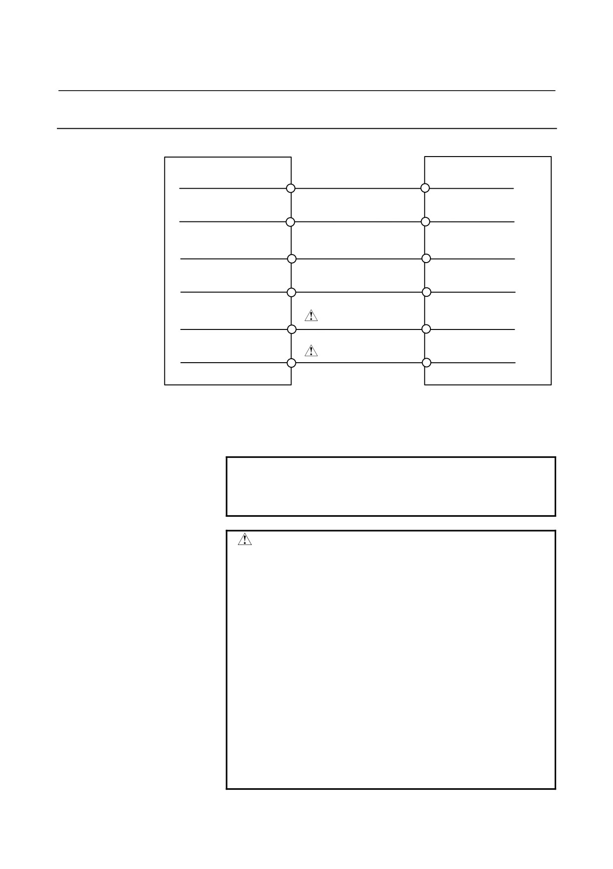
When a built-in regenerative discharge resistor is used
βi SVM
CZ6
A1
Install a jumper between the pins.
RC
A2
Cable specification:
RI
Two-conductor polyvinyl heavy-duty power cable
(JIS C3312),
Conductor size of 3.5 mm2,
Crimp terminal: 5.5-4
D-5000 series
Housing : 3-917807-2
Contact : 316041-6
Applicable wire range: 3.5 to 5.5 mm2
Manufacture : Tyco Electronics AMP
CXA20
Install a jumper between the pins.
1
2
Cable specification:
Two-conductor polyvinyl heavy-duty power cable
(JIS C3312),
Conductor size of 0.75 mm2,
Crimp terminal: 1.25-4
D-2000 series
Housing : 1-1318120-3
Contact : 1318107-1
Applicable wire: 0.3 to 0.85 mm2
Manufacture : Tyco Electronics AMP
For connection tools, see Subsection 9.2.3.
- 88 -
B-65322EN/02
SVM
9.TOTAL CONNECTION DIAGRAM
9.2.8
Details of Cable K6
βi SVM
βi SVM
CXA19B-A1
(24V)
CXA19A -A1
(24V)
CXA19B-B1
(24V)
CXA19A-B1
(24V)
CXA19B-A2
(0V)
CXA19A -A2
(0V)
CXA19B-B2
(0V)
CXA19A-B2
(0V)
CXA19B-A3
(ESP)
CXA19A -A3
(ESP)
WARNING
CXA19B-B3
(BAT)
CXA19A-B3
(BAT)
WARNING
D-2000 series
D-2000 series
Housing : 1-1318119-3
Housing : 1-1318119-3
Contact : 1318107-1
Contact : 1318107-1
Applicable wire: 0.3 to 0.85 mm2
Applicable wire: 0.3 to 0.85 mm2
Manufacture : Tyco Electronics AMP
Manufacture : Tyco Electronics AMP
NOTE
The (B3)BATL is the interface used to connect the
batteries for the absolute Pulsecoder. For details,
see the description of battery connection.
WARNING
1 When connecting two or more servo amplifiers, be
careful about the way the ESP (A3) is connected,
because even when the emergency stop button is
pressed, it may fail to stop the motor promptly. For
details, see "Details of Cable K8."
2 When using the built-in battery (A06B-6093-K001),
never connect the BAT(B3) of the connector
CXA19A/CXA19B.
Otherwise, a short-circuit will occur between the
battery output voltages for different SVMs, possibly
resulting in the batteries becoming very hot, which is
dangerous.
3 Do not connect more than one battery to the same
BAT(B3) line. Otherwise, a short-circuit will occur
between the output voltages of different batteries,
possibly resulting in the batteries becoming very hot,
which is dangerous.
- 89 -
9.TOTAL CONNECTION DIAGRAM
SVM
B-65322EN/02
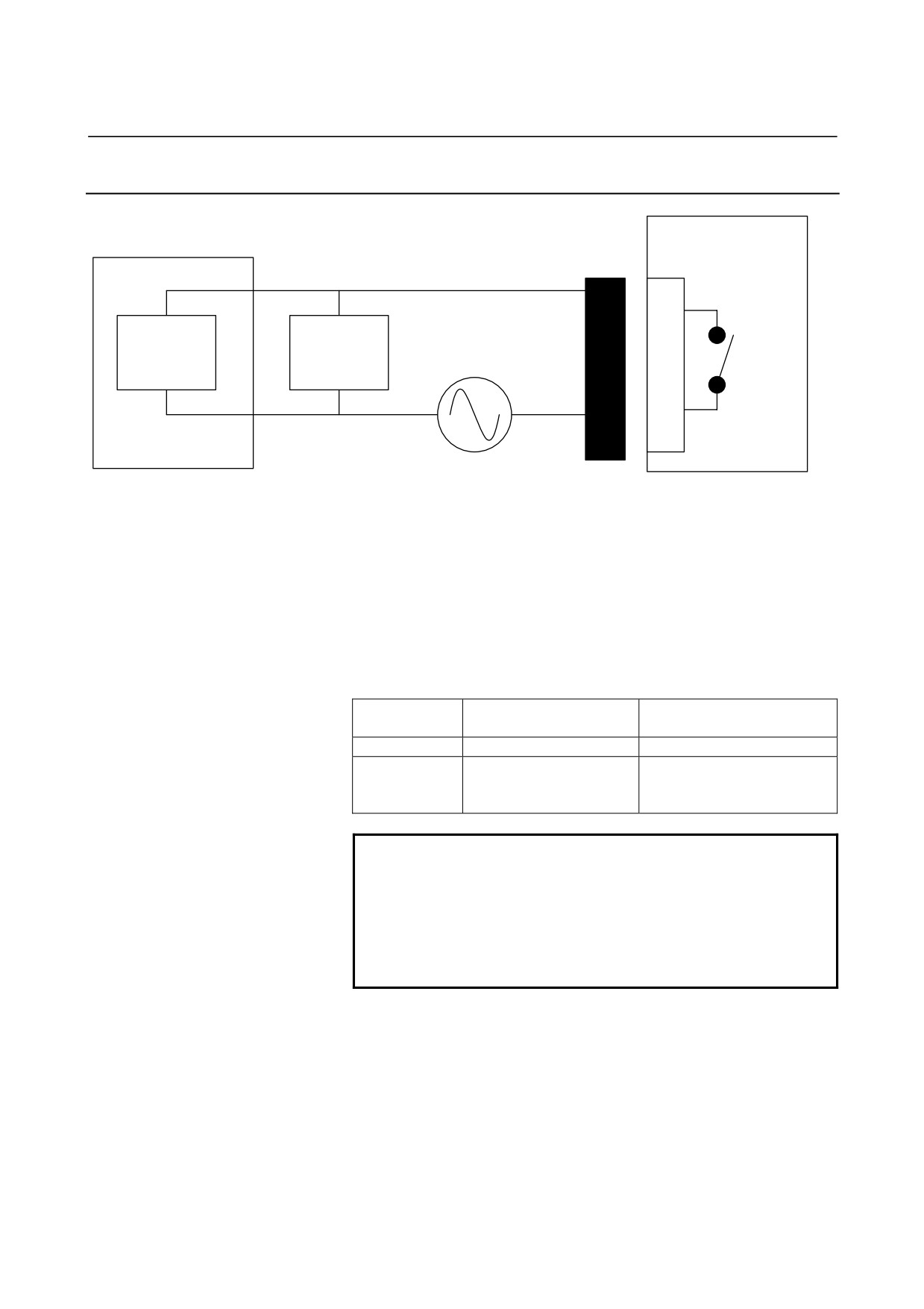
9.2.9
Details of Cable K7
βi SVM
MCC
CX29
1
Spark killer
Internal
Coil
contact
3
External power supply
(Use an appropriate power supply for the coil voltage
the customer uses.)
D-2000 series
Housing : 3-1318130-3
Contact : 1318107-1
Applicable wire: 0.3 to 0.85 mm2
Manufacture : Tyco Electronics AMP
For connection tools, see Subsection 9.2.3.
Internal contact capacity
Resistance load
Inductive load
(COS φ=1)
(COS φ=0.4, L/R=15msec)
Rated load
250VAC, 3A / 24VDC, 5A
250VAC, 2A / 24VDC, 1A
Maximum
5A
5A
contact
capacity
NOTE
1 To protect the internal contact, be sure to insert a
spark killer (CR) that matches the magnetic
contactor used.
2 When more than one servo amplifier is connected,
the cabling of the second and subsequent
amplifiers may be omitted.
- 90 -
B-65322EN/02
SVM
9.TOTAL CONNECTION DIAGRAM
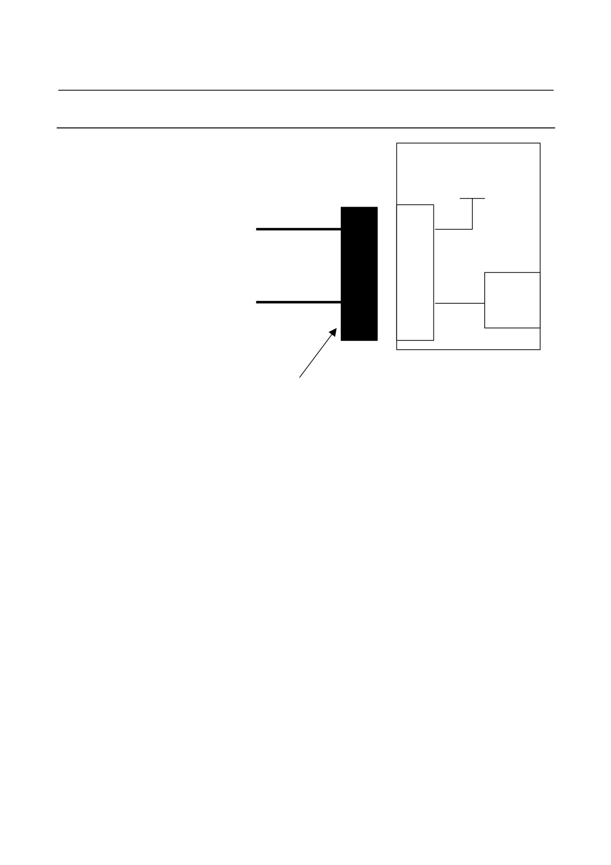
9.2.10 Details of Cable K8
βi SVM
24V
CX30
1
3
Receiver
*ESP
circuit
D-2000 series
Housing : 2-1318120-3
Contact : 1318107-1
Applicable wire: 0.3 to 0.85mm2
Manufacture : Tyco Electronics AMP
For connection tools, see Subsection 9.2.3.
(1) When the contact is ON (closed), the servo motor is operational.
When the contact is OFF (open), the external magnetic contactor
(MCC) is in the off state, and the servo motor does not operate.
(2) When the contact is set to OFF (open) while the motor is turning,
the servo motor is stopped by the dynamic brake.
(3) The contact input signal is defined as follows:
<1> As the external contact capacity, a voltage of at least 30
VDC and a current of at least 100 mA are required.
<2> When contactless input is used, the significant levels (the
voltage across the input pin) are as follows:
Low level "logic 0":
2 V or less
High level "logic 1":
20 V or more
- 91 -
9.TOTAL CONNECTION DIAGRAM
SVM
B-65322EN/02
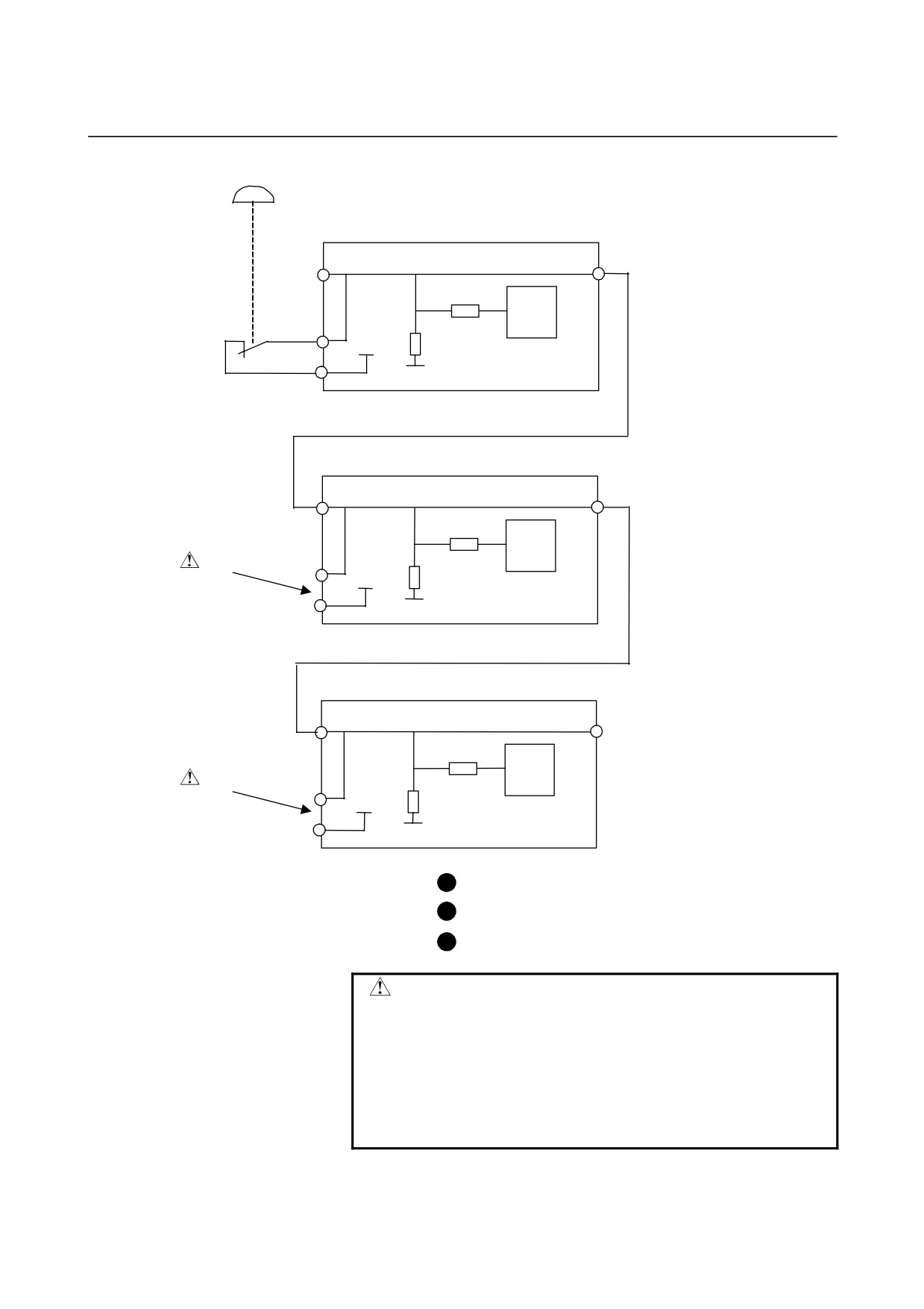
Emergency stop signal (*ESP) block diagram
CXA19A-A3
Control
RV
LSI
βiSVM for 1st axis
CX30-3
24V
R
0V
CX30-1
CXA19A-A3
CXA19B-A3
Control
RV
LSI
βiSVM for 2nd axis
CX30-3
WARNING
24V
R
0V
CX30-1
CXA19A-A3
Control
RV
LSI
WARNING
βiSVM for 3rd axis
CX30-3
24V
R
0V
CX30-1
WARNING
When connecting more than one amplifier, leave
connector CX30 of every amplifier for the second
and subsequent axes open.
(Never connect these connectors with a wire, a
switch, or the like.)
Even when the emergency stop button is pressed,
the motors may not stop immediately.
- 92 -
B-65322EN/02
SVM
9.TOTAL CONNECTION DIAGRAM
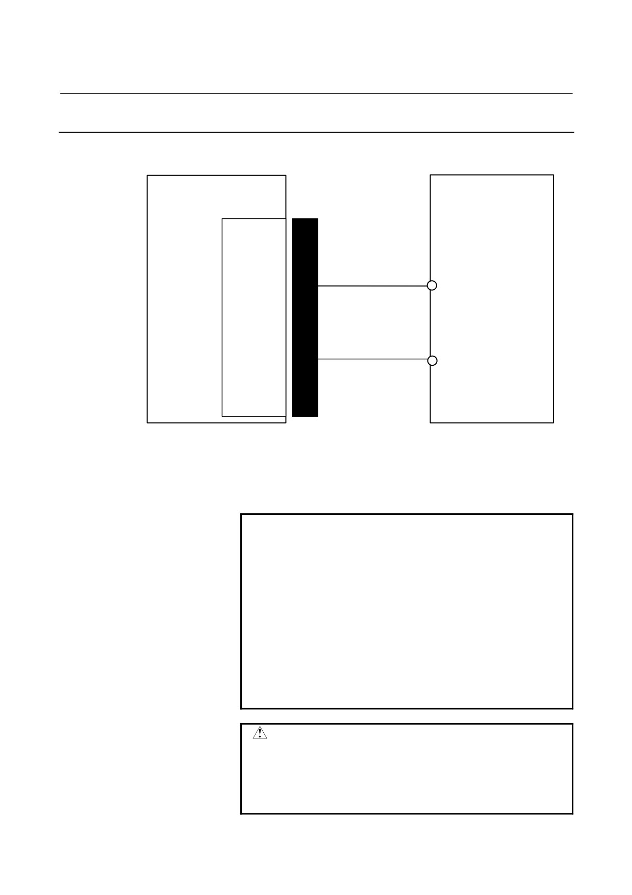
9.2.11 Details of Cable K9
Battery case
βi SVM
A06B-6050-K060
CXA19A
Battery
A06B-6050-K061
24V
24V
A2
0V
0V
0V
ESP
B3
BAT
6V
D-2000 series
Crimp terminal : 1.25-2
Housing : 1-1318119-3
Applicable wire : 0.3 to 0.85mm2
Contact : 1318107-1
Applicable wire : 0.3 to 0.85mm2
Manufacture : Tyco Electronics AMP
For connection tools, see Subsection 9.2.3.
NOTE
1 Because the battery requires periodic
maintenance, the above connection method is
recommended, where easily available commercial
batteries (four size D alkaline batteries) can be
used.
2 Servo motors for six axes can be connected to one
battery unit.
3 If servo motors for six axes are connected to the
battery unit, the service life of the battery unit is
about two years for the βi series servo motors or
about one year for the β series servo motors. The
battery should be replaced periodically.
WARNING
Do not connect more than one battery to the same
BATL(B3) line. Otherwise, a short-circuit will
occur between the output voltages of different
batteries, possibly resulting in the batteries
becoming very hot, which is dangerous.
- 93 -
9.TOTAL CONNECTION DIAGRAM
SVM
B-65322EN/02
9.2.12 Details of Cable K10
(1) Incorporating built-in batteries in each SVM
(For SVM1-4i or SVM1-20i)
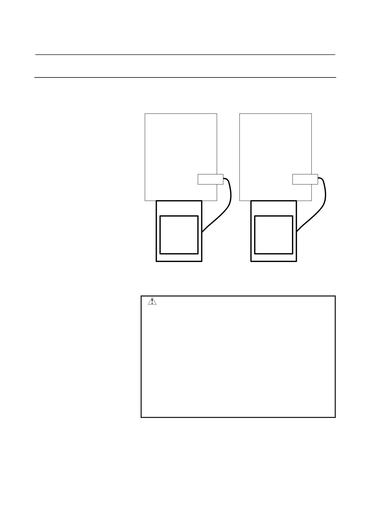
SVM
SVM
CX5X
CX5X
Battery case
Battery case
A06B-6093-K002
A06B-6093-K002
Battery
Battery
A06B-6093-K001
A06B-6093-K001
-
Using the built-in battery (A06B-6093-K001) requires the
battery case (A06B-6093-K002).
WARNING
1 When using the built-in battery (A06B-6093-K001),
never connect the BAT(B3) of the connector
CXA19A/CXA19B.
Otherwise, a short-circuit will occur between the
output voltages of different SVM batteries, possibly
resulting in the batteries becoming very hot, which
is dangerous.
2 Do not connect more than one battery to the same
BAT(B3) line.
Otherwise, a short-circuit will occur between the
output voltages of different batteries, possibly
resulting in the batteries becoming very hot, which
is dangerous.
- 94 -
B-65322EN/02
SVM
9.TOTAL CONNECTION DIAGRAM
(2) Incorporating built-in batteries in each SVM
(For SVM1-40i or SVM1-80i)
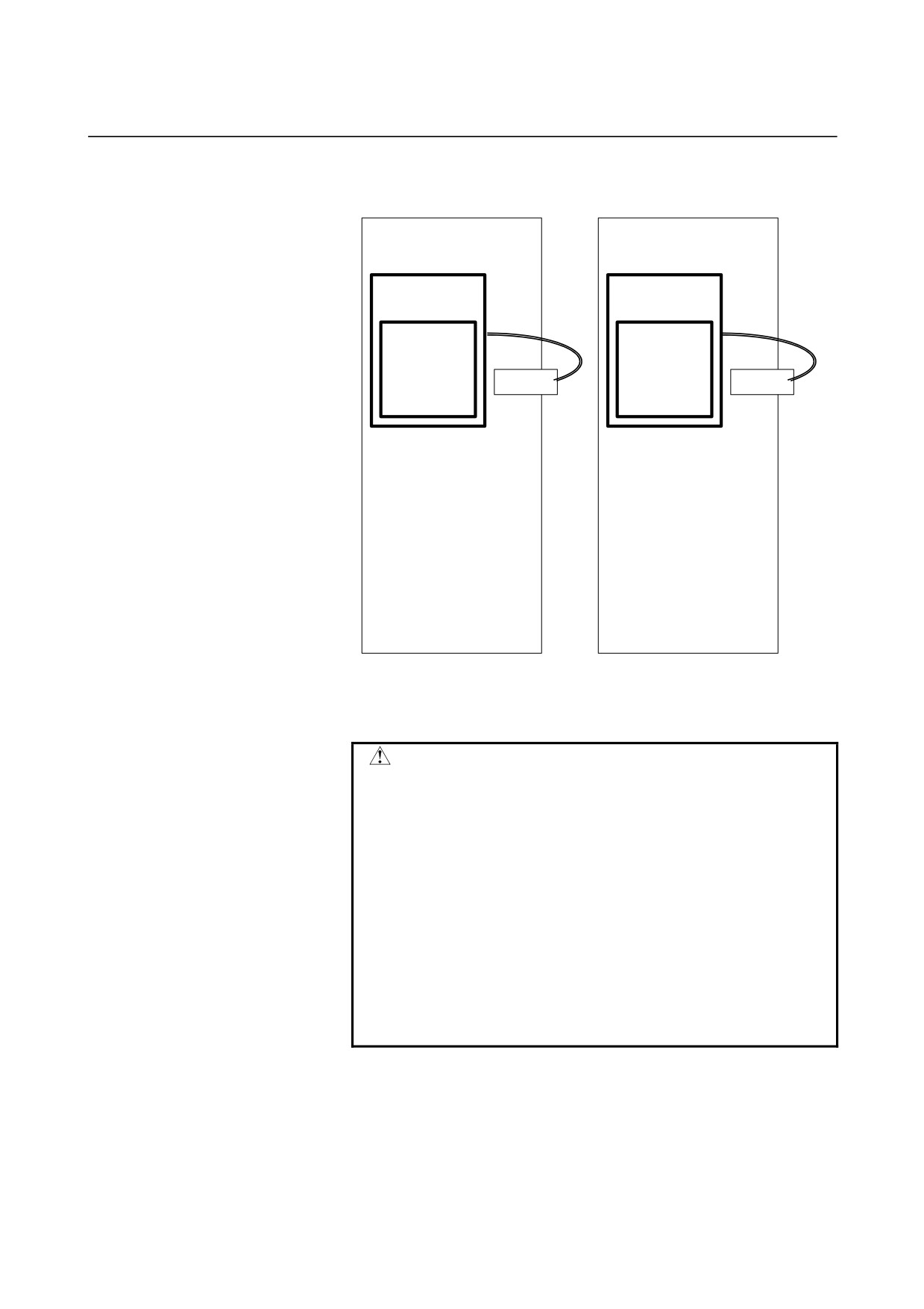
SVM
SVM
Battery case
Battery case
A06B-6093-K002
A06B-6093-K002
Battery
Battery
A06B-6093-K001
A06B-6093-K001
CX5X
CX5X
-
Using the built-in battery (A06B-6093-K001) requires the
battery case (A06B-6093-K002).
WARNING
1 When using the built-in battery (A06B-6093-K001),
never connect the BAT(B3) of the connector
CXA19A/CXA19B.
Otherwise, a short-circuit will occur between the
output voltages of different SVM batteries, possibly
resulting in the batteries becoming very hot, which
is dangerous.
2 Do not connect more than one battery to the same
BAT(B3) line.
Otherwise, a short-circuit will occur between the
output voltages of different batteries, possibly
resulting in the batteries becoming very hot, which
is dangerous.
- 95 -
9.TOTAL CONNECTION DIAGRAM
SVM
B-65322EN/02
9.2.13
Details of Cable K11
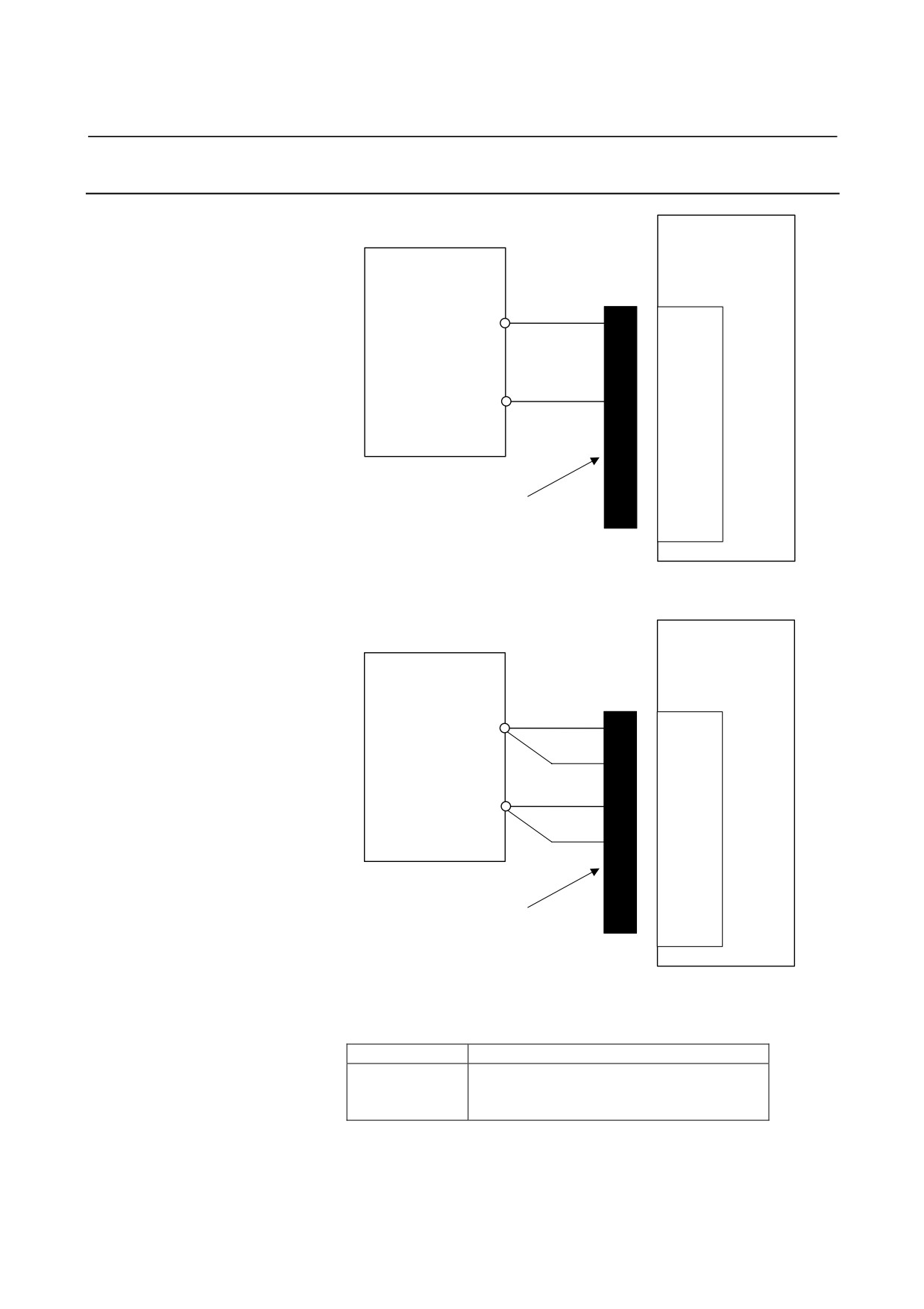
βi SVM
Stabilized power supply
CXA19
(24VDC)
B
A1
24V
24V
24V
A2
0V
0V
0V
ESP
D-2000 series
Housing : 1-1318119-3
BAT
Contact : 1318107-1
Applicable wire : 0.3 to 0.85mm2
Manufacture : Tyco Electronics AMP
Up to four units can be connected (when AWG#18 cable is used).
βi SVM
Stabilized power supply
(24VDC)
CXA19B
A1
24V
24V
B1
24
V
A2
0V
0V
B2
0V
ESP
D-2000 series
BAT
Housing : 1-1318119-3
Contact : 1318107-1
Applicable wire : 0.3 to 0.85mm2
Manufacture : Tyco Electronics AMP
Up to eight units can be connected (when AWG#18 cable is used)
Maximum permissible current of the connector
When only one pin is connected
Maximum
4 A/pin (when AWG#18 cable is used)
permissible
current
For connection tools, see Subsection 9.2.3.
- 96 -
B-65322EN/02
SVM
9.TOTAL CONNECTION DIAGRAM
9.3
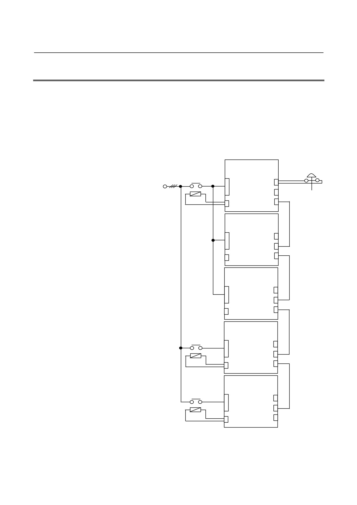
HANDLING OF EXTERNAL MAGNETIC CONTACTORS
This section explains how to handle external magnetic contactors
when FSSB interface SVMs and I/O Link interface SVMs are used
together.
1
Multiple FSSB interface SVMs can share an external magnetic
contactor. Determine the capacity of the magnetic contactor
from the sum of the power supply ratings of the SVMs.
2
It is recommended that one external magnetic
contactor
be
prepared for each I/O link interface SVM.
FSSB interface
βi SVM
Magnetic
CZ4
CX30
contactor
or
CZ7
CXA19B
3φ 200VAC
CXA19A
CX29
FSSB interface
βi SVM
CZ4
CX30
or
CZ7
CXA19B
CXA19A
CX29
FSSB interface
βi SVM
CZ4
CX30
or
CZ7
CXA19B
CXA19A
CX29
I/O Link interface
βi SVM
Magnetic
CZ4
CX30
contactor
or
CZ7
CXA19B
CXA19A
CX29
I/O Link interface
βi SVM
Magnetic
contactor
CZ4
CX30
or
CZ7
CXA19B
CXA19A
CX29
- 97 -
10.HEAT DISSIPATION
SVM
B-65322EN/02
10
HEAT DISSIPATION
The amount of heat dissipation depends on the SVM model and the
current that flows through the servo motor. For the current that flows
through a servo motor, reference the continuous rated current of each
servo motor. (For the continuous rated current of each servo motor,
refer to the servo motor descriptions.) As the current that flows
through a servo motor, the root-mean-square value of the current that
flows through an actual servo motor on a machine can be used. The
amount of heat dissipation indicated below assumes the use of HRV2.
(1)
Total amount of heat dissipation
The total amount of heat dissipation is calculated according to
the following expression:
Total amount of heat dissipation= a + Ka1 × b1
a
: Amount of heat dissipation determined by the SVM
model [W]
Ka1 : Coefficient determined by the SVM [W/Arms]
b1
: Current flowing through the servo motor [Arms]
Total amount of heat dissipation
a
K
Name
Specification
[W]
[W/Arms]
SVM1-4i
H001
20
Ka1: 8.1
SVM1-20i
H002
20
Ka1: 7.7
SVM1-40i
H003
20
Ka1: 7.1
SVM1-80i
H004
20
Ka1: 6.7
(2)
Residual amount of heat in the cabinet
By placing the heat sink section outside the cabinet, the residual
amount of heat in the cabinet can be calculated according to the
expression below.
Residual amount of heat in the cabinet= a + Kb1 × b1
a
: Amount of heat dissipation determined by the SVM
model [W]
Kb1 : Coefficient determined by the SVM [W/Arms]
b1
: Current flowing through the servo motor [Arms]
Residual amount of heat in the cabinet
a
K
Name
Specification
[W]
[W/Arms]
SVM1-4i
H001
20
Kb1: 8.1
SVM1-20i
H102
20
Kb1: 7.7
SVM1-40i
H003
20
Kb1: 1.4
SVM1-80i
H004
20
Kb1: 0.7
- 98 -
II. SVPM
B-65322EN/02
SVPM
1.OVERVIEW
1
OVERVIEW
The βi series SVPM has the following features:
(1) Because a power supply is incorporated, a system with two or
three servo axes and one spindle can be built easily.
(2) Multi-axis AC servo amplifier with excellent cost performance
(3) This unit is designed in compliance with the following safety
standards:
- EN50178
- UL508C
- CSA C22.2
- EN61000-6-2
- EN55011
(4) This multi-axis AC servo amplifier is suitable for the servo motor
βi series, which is suitable for feed axes of machining tools, and
the spindle motor βi series, which is suitable for a spindle.
- 101 -
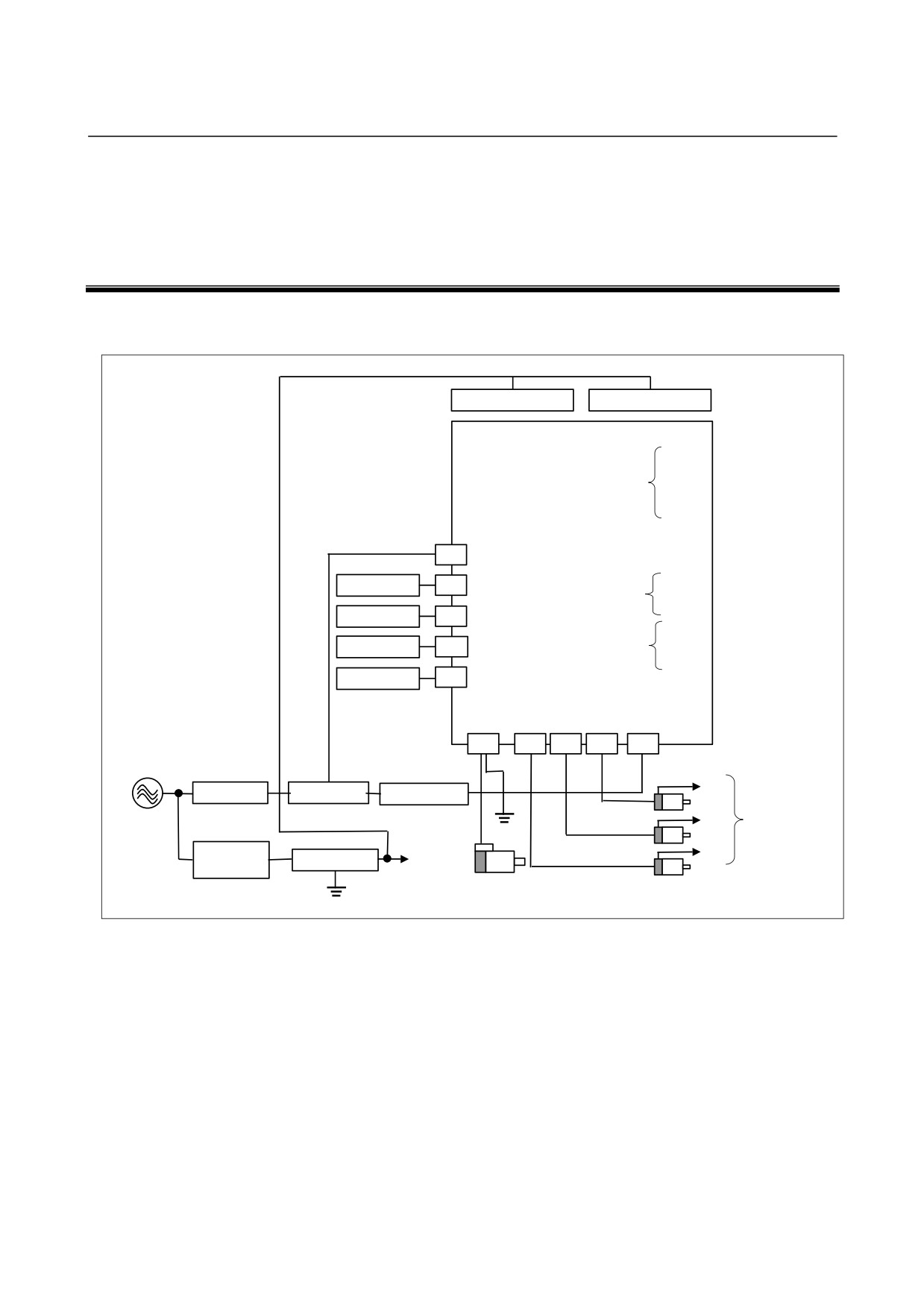
2.CONFIGURATION
SVPM
B-65322EN/02
2
CONFIGURATION
Configuration of βi series servo amplifier SVPM
Fan unit
Fan unit
SVPM
JF1
Servo Motor
Pulse Coder I/F
JF2
Servo Motor
JF3
Servo Motor
JX6
CX3
JY1
LM, SM, OVR
Emergency stop
CX4
JA7A
CNC
Spindle I/F
JA7B
CNC
CXA2C
24V power supply
JYA2
Spindle Motor
Battery
CX5X
Spindle Sensor
JYA3
Position Coder
CNC
COP10B
JYA4
(FSSB I/F)
TB2
CZ2L
CZ2M CZ2N
TB1
TB3
200 to 240 VAC
JF3
Circuit breaker 1
Magnetic contactor
AC reactor
JF2
Pulsecoder I/F
G
Circuit breaker 2
JF1
Lightning surge
Power
5A
absorber
supply for
equipment
Spindle
Servo
Motor
Motor
G
- 102 -
B-65322EN/02
SVPM
3.SPECIFICATIONS
3
SPECIFICATIONS
- 103 -
3.SPECIFICATIONS
SVPM
B-65322EN/02
3.1
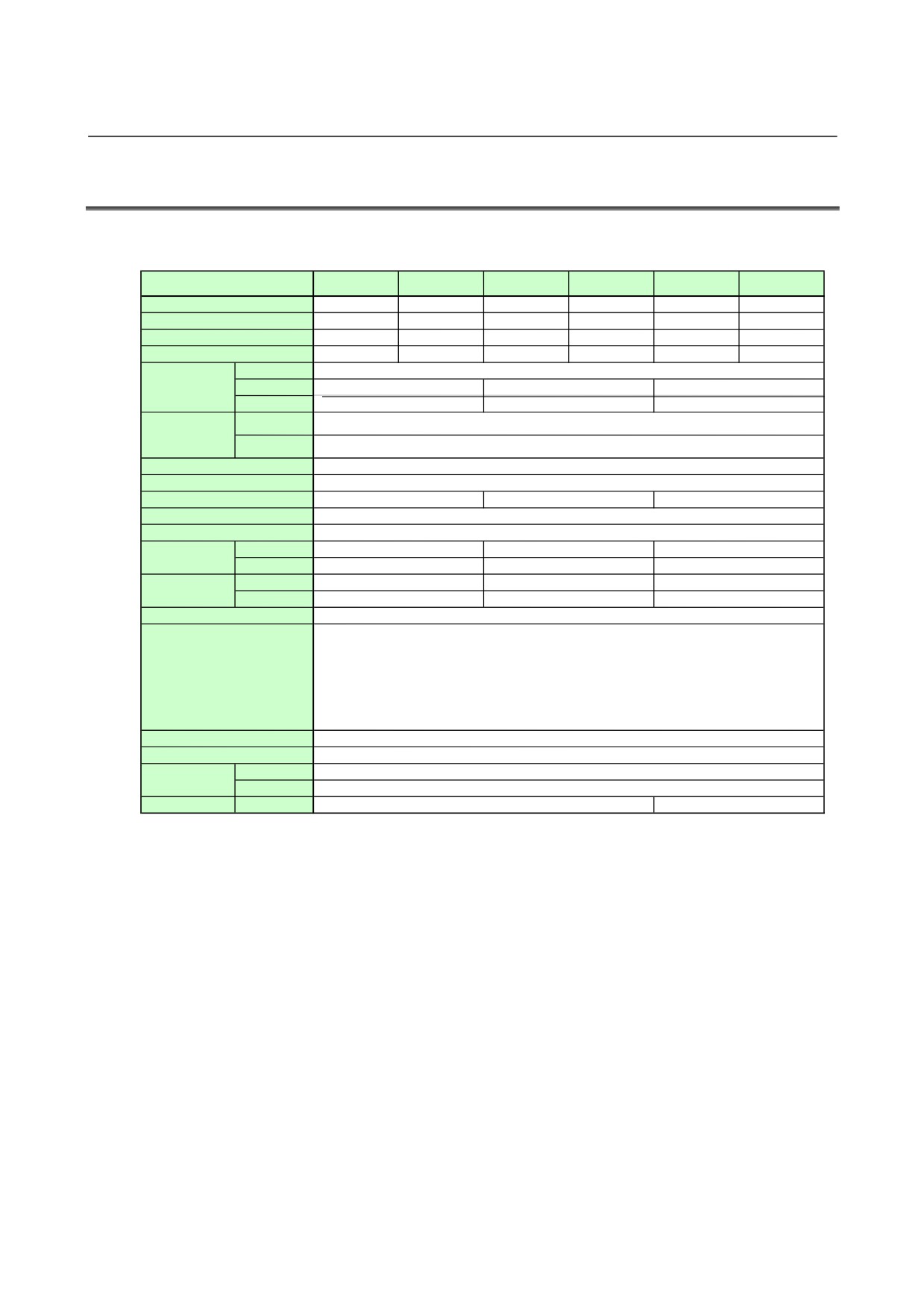
SPECIFICATIONS
Two-axis type (SVPM2)
SVPM2-5.5i
SVPM2-5.5i
SVPM2-11i
SVPM2-11i
SVPM2-15i
SVPM2-15i
Item
(TypeA)
(TypeC)
(TypeA)
(TypeC)
(TypeA)
(TypeC)
Unit specification
A06B-6134-H201#A A06B-6134-H201#CA06B-6134-H202#A A06B-6134-H202#CA06B-6134-H203#A A06B-6134-H203#C
Power PC board
A20B-2101-0020
A20B-2101-0020
A20B-2101-0021
A20B-2101-0021
A20B-2101-0022
A20B-2101-0022
Control PC board
A20B-2101-0012
A20B-2101-0012
A20B-2101-0012
A20B-2101-0012
A20B-2101-0012
A20B-2101-0012
Module PC board
A20B-2902-0670
A20B-2902-0672
A20B-2902-0670
A20B-2902-0672
A20B-2902-0670
A20B-2902-0672
Input voltage
200-240VAC (+10%,-15%) 50/60Hz
Main power supply
Input current (50Hz)
26Arms
49Arms
64Arms
3-phase input
Power supply rating
9KVA
17KVA
22KVA
Input voltage
24VDC±10%
Control power supply
Input current
1.5Amax.
Control method
Sine wave PWM control with Transistor Bridge
Servo HRV control
HRV2, HRV3
Rated output current of spindle
29Arms
56Arms
64Arms
Basic output frequency of spindle
60Hz
Output frequency range of spindle
1Hz-1KHz
Rated output current
L axis
6.5Arms
6.5Arms
13Arms
of servo axis
Maxis
6.5Arms
6.5Arms
13Arms
Maximum output
L axis
20A
20A
40A
current of servo axis
M axis
20A
20A
40A
Output frequency range of servo axis
0Hz-334Hz
High Current
IPM Abnormal
High Voltage of DC Link
Protection function
Low Voltage of DC Link
Low Voltage of Control Power Supply
Short Time Overload
FSSB Communication Error
Ambient temperature range
0-+55 °C
Weight
14.8kg
Dimensions
Outside dimensions
260x380x272
Fin dimensions
260x380x100
Option
AC reactor
A81L-0001-0155
A81L-0001-0156
- 104 -