FANUC AC Servo Amplifiers βi Series. Description Manual (B-65322EN/02) - page 8
7.GROUNDING
I/O Link
B-65322EN/02
7
GROUNDING
- 198 -
B-65322EN/02
I/O Link
7.GROUNDING
7.1
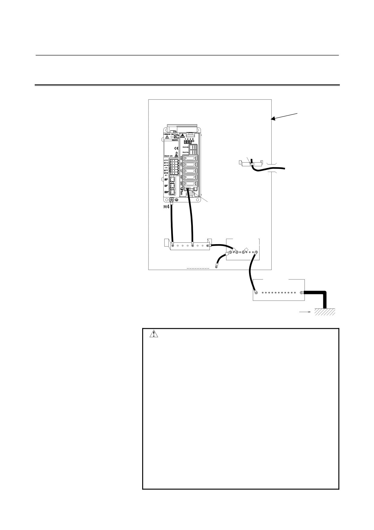
SVM1-4i AND SVM1-20i
Cabinet
Clamp shield
External shielded
cable
Signal grounding
terminal
Distribution
panel
Ground plate
Connected to cabinet
Distribution
panel
Class-3 ground or higher
CAUTION
1 Ground the shield of the cable drawn from the
outside of the cabinet to the ground plate provided
near the cabinet inlet with a clamp. This is to
prevent noise on the cable shield outside the
cabinet from getting into the cabinet and also to
prevent noise inside the cabinet from radiating
outside.
2 Connect the FG terminal of the βi SVM to a ground.
Use a Faston terminal (A65L-0001-0148/2) as the
terminal on the βi SVM side. Use a 2-mm2 or
thicker twisted cable with a length of around 100 to
300 mm for installation. If the FG terminal is not
grounded as mentioned here, the unit becomes
more susceptible to noise.
3 The flange of the βi SVM has an M4 threaded hole
for grounding. Use this hole for grounding as
shown in the above figure.
- 199 -
7.GROUNDING
I/O Link
B-65322EN/02
7.2
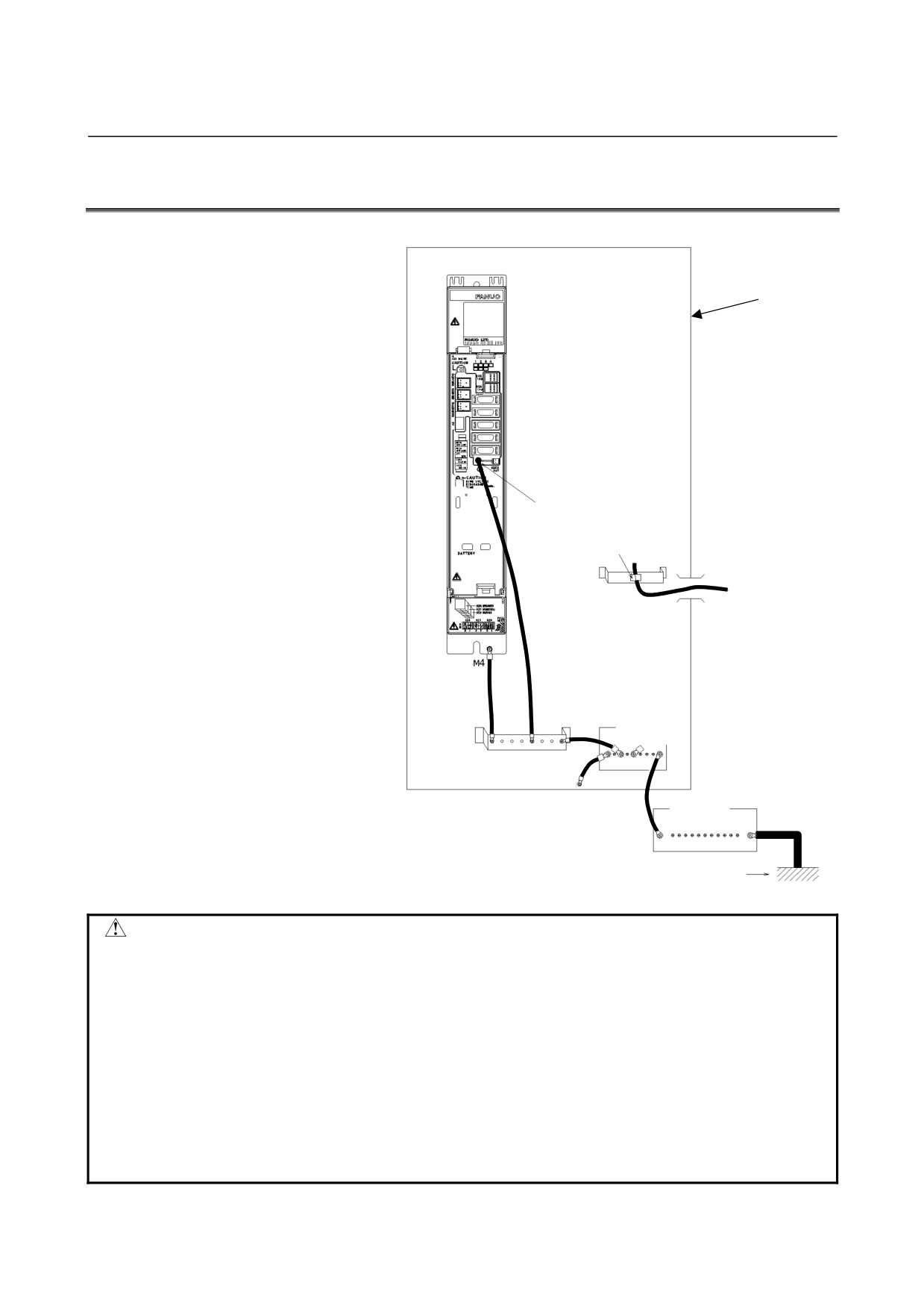
SVM1-40i and SVM1-80i
Cabinet
signal grounding
terminal
Clamp shield
External shielded
cable
Distribution
panel
Ground plate
Connected to cabinet
Distribution
panel
Class-3 ground or higher
CAUTION
1 Ground the shield of the cable drawn from the outside of the cabinet to the ground
plate provided near the cabinet inlet with a clamp. This is to prevent noise on the
cable shield outside the cabinet from getting into the cabinet and also to prevent
noise inside the cabinet from radiating outside.
2 Connect the signal grounding terminal of the βi SVM to a ground. Use a Faston
terminal (A65L-0001-0148/2) as the terminal on the βi SVM side. Use a 2-mm2 or
thicker twisted cable with a length of around 100 to 300 mm for installation. If the
signal grounding terminal is not grounded as mentioned here, the unit becomes
more susceptible to noise.
3 The flange of the βi SVM has an M4 threaded hole for grounding. Use this hole
for grounding as shown in the above figure.
- 200 -
B-65322EN/02 I/O Link 8.EXTERNAL DIMENSIONS / PANEL CUT-OUT DRAWINGS / MAINTENANCE AREA
8
EXTERNAL DIMENSIONS / PANEL
CUT-OUT DRAWINGS / MAINTENANCE
AREA
- 201 -
8.EXTERNAL DIMENSIONS / PANEL CUT-OUT DRAWINGS / MAINTENANCE AREA I/O Link B-65322EN/02
8.1
EXTERNAL DIMENSIONS
8.1.1
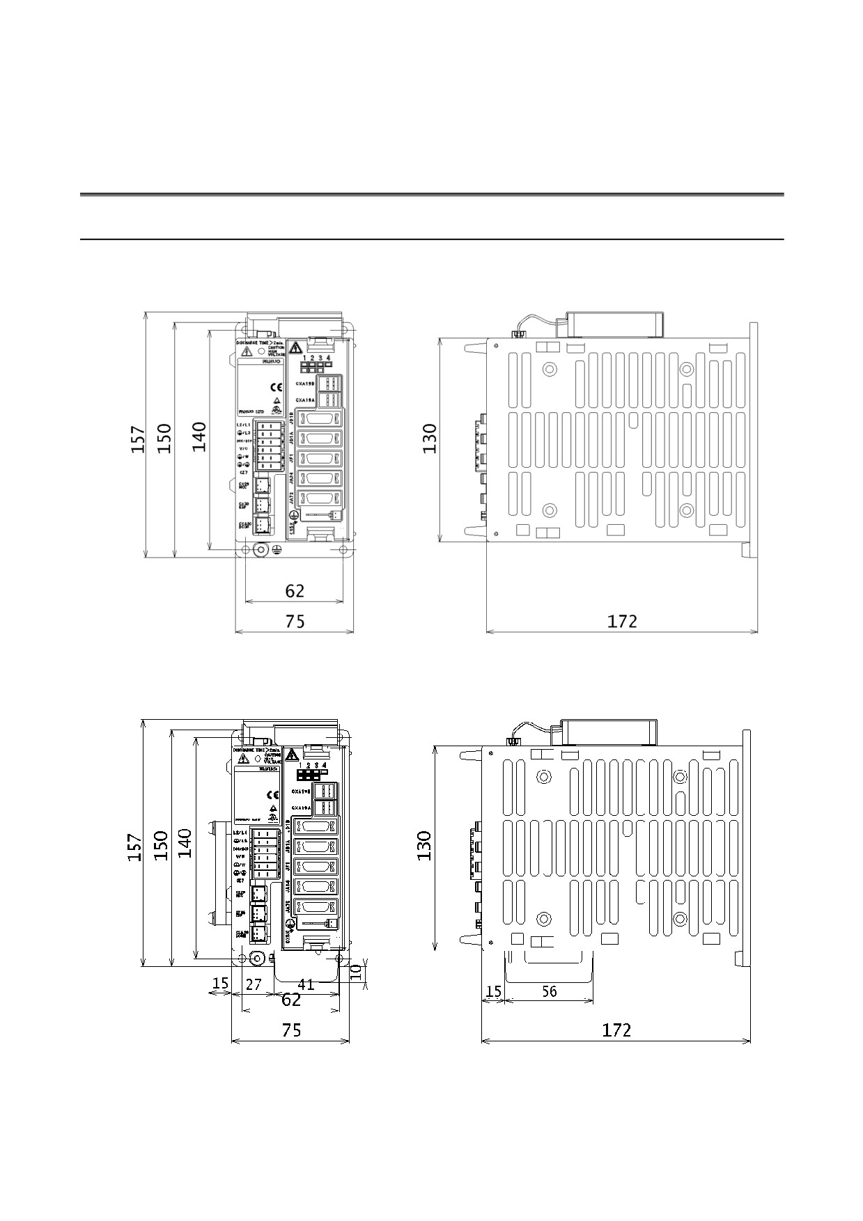
SVM1-4i and SVM1-20i
βi SVM with the separated regenerative discharge unit and the battery
(dedicated lithium battery) not installed
βi SVM with the separated regenerative discharge unit and the battery
(dedicated lithium battery) installed
- 202 -
B-65322EN/02 I/O Link 8.EXTERNAL DIMENSIONS / PANEL CUT-OUT DRAWINGS / MAINTENANCE AREA
8.1.2
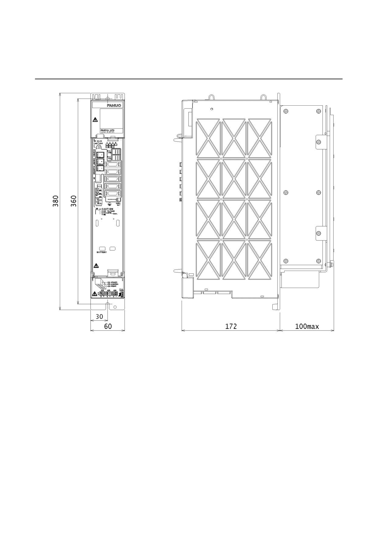
SVM1-40i and SVM1-80i
- 203 -
8.EXTERNAL DIMENSIONS / PANEL CUT-OUT DRAWINGS / MAINTENANCE AREA I/O Link B-65322EN/02
8.1.3
Fan Unit (A06B-6134-K002)
See Subsection
8.1.4
“External Dimensions of Fan Unit
(A06B-6134-K002)" in Part I.
8.1.4
Separated Regenerative Discharge Resistor
See Subsection 8.1.5 “Discharge Resistor" in Part I.
8.1.5
AC Line Filter
See Subsection 8.1.6 “AC Line Filter" in Part I.
8.1.6
Transformer for Exports
See Subsection 8.1.7 “Transformer for Exports" in Part I.
8.1.7
Battery Case (for Size D Alkaline Battery)
See Subsection 8.1.8 “Battery Case" in Part I.
8.1.8
Lightning Surge Absorbers
See Subsection 8.1.9 “Lightning Surge Absorbers" in Part I.
8.2
PANEL CUT-OUT DRAWINGS
See Section 8.2 “PANEL CUT-OUT DRAWINGSS" in Part I.
- 204 -
B-65322EN/02 I/O Link 8.EXTERNAL DIMENSIONS / PANEL CUT-OUT DRAWINGS / MAINTENANCE AREA
8.3
MAINTENANCE AREA
8.3.1
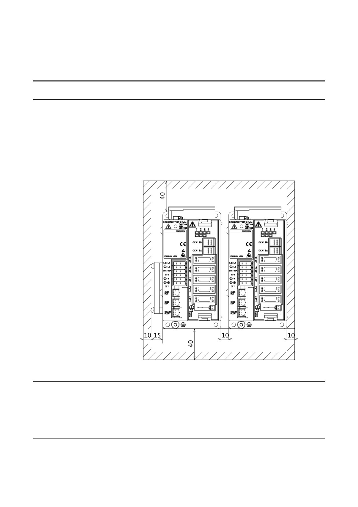
Maintenance Area for the SVM1-4i and SVM1-20i
The maintenance area varies depending on whether the separated
regenerative discharge unit (A06B-6130-H401) is used or not. For
details, see the figure below. The maintenance area when the
separated regenerative discharge unit (A06B-6130-H401) is installed
is shown on the left side of the figure, and the maintenance area when
the separated regenerative discharge unit (A06B-6130-H401) is not
installed is shown on the right side. When the battery for the
absolute pulse coder (dedicated lithium battery) is installed, the same
maintenance area applies.
8.3.2
Maintenance Area for the SVM1-40i
See "When no cooling fan AC motor (A06B-6134-K002) is used to
cool the heat sink" in Subsection 8.3.2, "Maintenance Area for the
SVM1-40i and SVM1-80i" in Part I.
8.3.3
Maintenance Area for the SVM1-80i
See "When the cooling fan AC motor (A06B-6134-K002) is used to
cool the heat sink" in Subsection 8.3.2, "Maintenance Area for the
SVM1-40i and SVM1-80i" in Part I.
- 205 -
9.TOTAL CONNECTION DIAGRAM
I/O Link
B-65322EN/02
9
TOTAL CONNECTION DIAGRAM
- 206 -
B-65322EN/02
I/O Link
9.TOTAL CONNECTION DIAGRAM
9.1
CONNECTION DIAGRAM
9.1.1
SVM1-4i and SVM1-20i
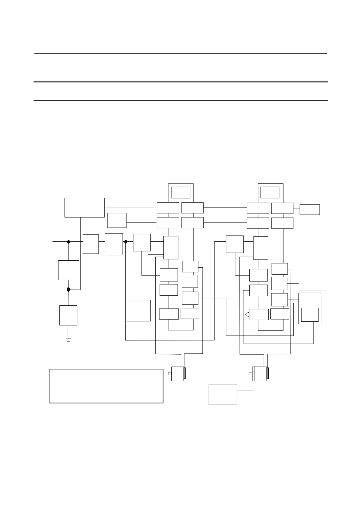
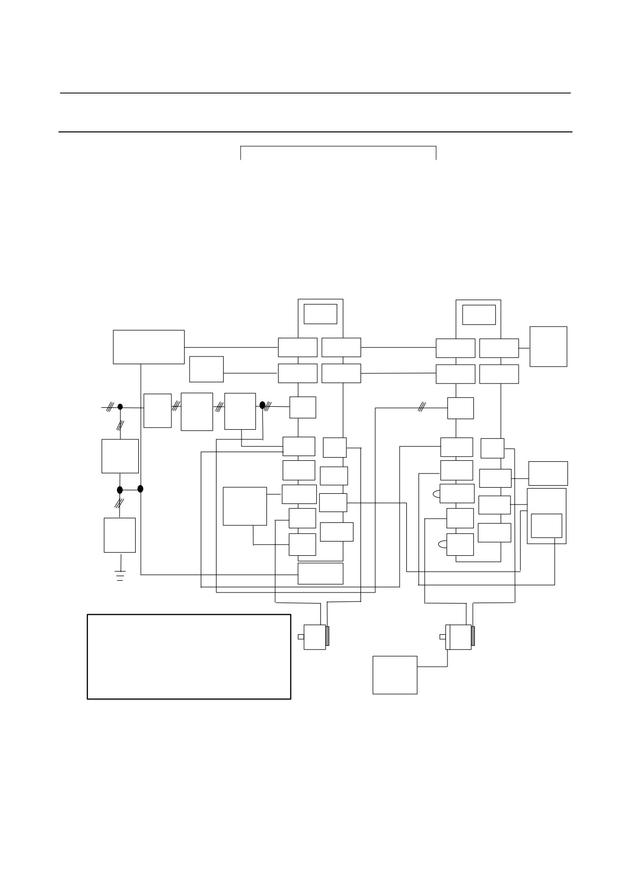
This subsection shows a connection example of a 2-axis system using
two SVM units which are the SVM1-4i or SVM1-20i.
In this example, a separated regenerative discharge unit is connected
but no external pulse generator is connected to the SVM unit for the
first axis (the unit nearer the CNC), while no separated regenerative
discharge unit is connected but an external pulse generator is
connected to the SVM unit for the second axis.
SVM1-4i or
SVM1-4i or
SVM1-20i
SVM1-20i
FUSE
FUSE
Stabilized
K11
K6
K9
power supply
CXA19B
CXA19A
CXA19B
CXA19A
Battery
24 VDC
case
CNC
K20
K20
JD1B
JD1A
JD1B
JD1A
3-phase : 200 to 240 VAC
1-phase : 220 to 240 VAC
Circuit
AC
Magnetic
K2
K2
CZ7
Magnetic
CZ7
line
contactor
breaker
contactor
filter
K4
5 A
JF1
JF1
Circuit
K7
K7
breaker
CX29
CX29
JA34
K22
JA34
External pulse
generator
CX30
CX30
JA72
K21
K21
Machine
JA72
operator’s
Separated
panel
regenerative
K5
Lightning
K5
Emergency
discharge
CXA20
CX5X
CX5X
surge
CXA20
stop switch
resistor
absorber
K10
K10
K8
K3
K1
K3
K1
CAUTION
1 A circuit breakers, magnetic contactor, and AC line filter are
always required.
2 Use the stabilized 24VDC power supply for the βi SVM.
24 V power
24VDC power supply for the βi SVM and 24VDC power
supply for
supply for the motor brake cannot be shared.
motor brake
- 207 -
9.TOTAL CONNECTION DIAGRAM
I/O Link
B-65322EN/02
NOTE
1 Always install the circuit breakers, magnetic
contactor, and AC line filter.
2 To protect the equipment from lightning surge
voltages, install a lightning surge absorber across
each pair of power lines and across each power line
and the grounding line at the power inlet of the
power magnetics cabinet.
WARNING
Defects, such as a loose screw and an incorrectly
inserted connector, can lead to a motor malfunction,
excessive heat generation, and a ground fault.
Exercise adequate care in installing servo
amplifiers.
A loose screw (or, if a connector is used, a loose
connector contact or an incorrect connector
pin-to-cable connection) on high-current carrying
power supply wires or motor power wires can lead
to fire. Exercise adequate care in wiring.
- 208 -
B-65322EN/02
I/O Link
9.TOTAL CONNECTION DIAGRAM
9.1.2
SVM1-40i and SVM1-80i
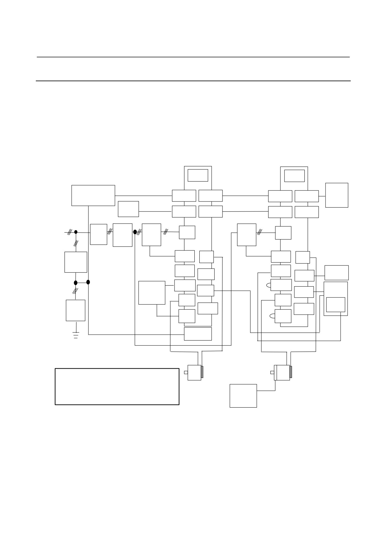
This subsection shows a connection example of a 2-axis system using
the SVM1-80i for the first axis (the unit nearer the CNC) and the
SVM1-40i for the second axis.
In this example, a separated regenerative discharge unit is connected
but no external pulse generator is connected for the first axis, while no
separated regenerative discharge unit is connected but an external
pulse generator is connected for the second axis.
SVM1-80i
SVM1-40i
FUSE
FUSE
Battery
Stabilized
K11
K6
K9
case
power supply
CXA19B
CXA19A
CXA19B
CXA19A
24 VDC
CNC
K20
K20
JD1B
JD1A
JD1B
JD1A
3-phase : 200 to 240 VAC
Circuit
AC line
Magnetic
K2
Magnetic
K2
CZ4
CZ4
breaker
filter
contactor
contactor
K7
K7
5 A
CX29
JF1
CX29
JF1
Circuit
breaker
CX30
K8
CX30
External
JA34
K22
pulse
JA34
generator
K5
K5
Separated
CXA20
CXA20
Machine
K21
K21
regenerative
JA72
JA72
operator’s
discharge
panel
CZ5
CZ5
Emergency
resistor
Lightning
stop switch
CX5X
CX5X
surge
K4
K4
absorber
CZ6
CZ6
K10
K10
Fan unit
K3
K1
K3
K1
CAUTION
1 A circuit breakers, magnetic contactor, and AC line filter are
always required.
2 Use the stabilized 24VDC power supply for the βi SVM.
24 V
24VDC power supply for the βi SVM and 24VDC power
power
supply for the motor brake cannot be shared.
supply for
motor
- 209 -
9.TOTAL CONNECTION DIAGRAM
I/O Link
B-65322EN/02
NOTE
1 Always install the circuit breakers, magnetic
contactor, and AC line filter.
2 To protect the equipment from lightning surge
voltages, install a lightning surge absorber across
each pair of power lines and across each power line
and the grounding line at the power inlet of the
power magnetics cabinet.
WARNING
Defects, such as a loose screw and an incorrectly
inserted connector, can lead to a motor malfunction,
excessive heat generation, and a ground fault.
Exercise adequate care in installing servo
amplifiers.
A loose screw (or, if a connector is used, a loose
connector contact or an incorrect connector
pin-to-cable connection) on high-current carrying
power supply wires or motor power wires can lead
to fire. Exercise adequate care in wiring.
- 210 -
B-65322EN/02
I/O Link
9.TOTAL CONNECTION DIAGRAM
9.1.3
SVM1-4i and SVM1-20i
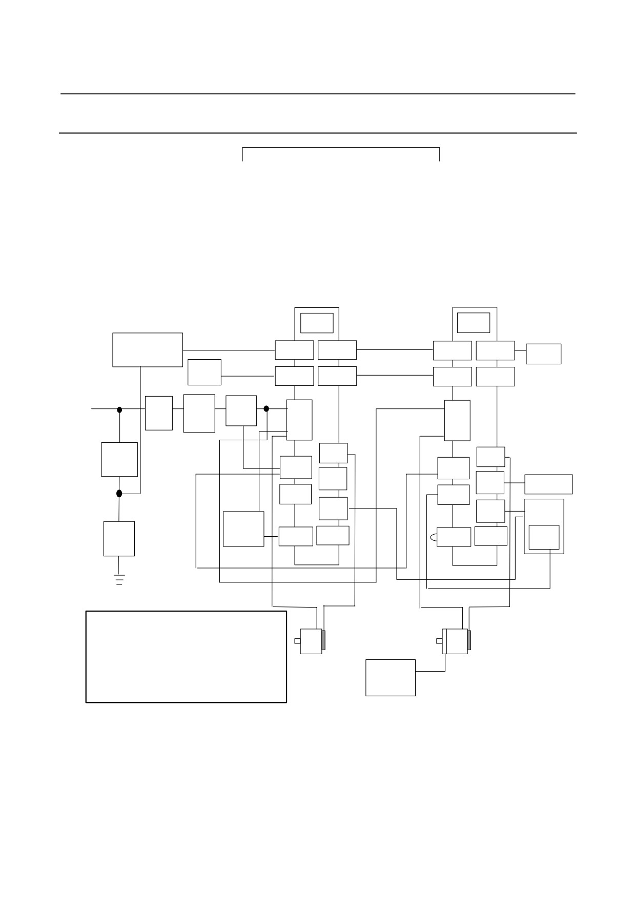
Example for sharing a magnetic contactor
This subsection shows a connection example of a 2-axis system using
two SVM units which are the SVM1-4i or SVM1-20i.
In this example, a separated regenerative discharge unit is connected
but no external pulse generator is connected to the SVM unit for the
first axis (the unit nearer the CNC), while no separated regenerative
discharge unit is connected but an external pulse generator is
connected to the SVM1unit for the second axis.
SVM1-4i or
SVM1-4i or
SVM1-20i
SVM1-20i
FUSE
FUSE
Stabilized
K11
K6
K9
power supply
CXA19B
CXA19A
CXA19B
CXA19A
Battery
24 VDC
case
CNC
K20
K20
JD1B
JD1A
JD1B
JD1A
3-phase : 200 to 240 VAC
1-phase : 220 to 240 VAC
Circuit
AC line
Magnetic
K2
K2
CZ7
CZ7
breaker
filter
contactor
K4
5 A
JF1
JF1
Circuit
K7
K7
CX29
CX29
breaker
JA34
K22
JA34
External pulse
generator
CX30
CX30
K21
JA72
K21
Machine
JA72
operator’s
Separated
panel
regenerative
K5
Lightning
K5
Emergency
discharge
CXA20
CX5X
CXA20
CX5X
stop switch
surge
resistor
absorber
K10
K10
K8
K3
K1
K3
K1
CAUTION
1 A circuit breakers, magnetic contactor, and AC line filter are
always required.
2 Use the stabilized 24VDC power supply for the βi SVM.
24VDC power supply for the βi SVM and 24VDC power
supply for the motor brake cannot be shared.
24 V power
3 If an alarm that turns off the magnetic contactor is issued in
supply for
an amplifier, an alarm indicating DC link voltage shortage is
issued in the other amplifiers.
motor brake
- 211 -
9.TOTAL CONNECTION DIAGRAM
I/O Link
B-65322EN/02
NOTE
1 Always install the circuit breakers, magnetic
contactor, and AC line filter.
2 To protect the equipment from lightning surge
voltages, install a lightning surge absorber across
each pair of power lines and across each power line
and the grounding line at the power inlet of the
power magnetics cabinet.
WARNING
Defects, such as a loose screw and an incorrectly
inserted connector, can lead to a motor malfunction,
excessive heat generation, and a ground fault.
Exercise adequate care in installing servo
amplifiers.
A loose screw (or, if a connector is used, a loose
connector contact or an incorrect connector
pin-to-cable connection) on high-current carrying
power supply wires or motor power wires can lead
to fire. Exercise adequate care in wiring.
- 212 -
B-65322EN/02
I/O Link
9.TOTAL CONNECTION DIAGRAM
9.1.4
SVM1-40i and SVM1-80i
Example for sharing a magnetic contactor
This subsection shows a connection example of a 2-axis system using
the SVM1-80i for the first axis (the unit nearer the CNC) and the
SVM1-40i for the second axis.
In this example, a separated regenerative discharge unit is connected
but no external pulse generator is connected for the first axis, while no
separated regenerative discharge unit is connected but an external
pulse generator is connected for the second axis.
SVM1-80i
SVM1-40i
FUSE
FUSE
Battery
Stabilized
K11
K6
K9
case
power supply
CXA19B
CXA19A
CXA19B
CXA19A
24 VDC
CNC
K20
K20
JD1B
JD1A
JD1B
JD1A
3-phase : 200 to 240 VAC
Circuit
AC line
Magnetic
K2
K2
CZ4
CZ4
breaker
filter
contactor
K7
K7
5 A
CX29
JF1
CX29
JF1
Circuit
breaker
CX30
K8
CX30
External
JA34
K22
pulse
JA34
generator
K5
CXA20
K5
CXA20
Machine
Separated
K21
JA72
K21
operator’s
regenerative
JA72
discharge
panel
CZ5
CZ5
Emergency
resistor
Lightning
stop switch
CX5X
CX5X
surge
K4
K4
absorber
CZ6
CZ6
K10
K10
Fan unit
K3
K1
K3
K1
CAUTION
1 A circuit breakers, magnetic contactor, and AC line filter are
always required.
2 Use the stabilized 24VDC power supply for the βi SVM.
24VDC power supply for the βi SVM and 24VDC power
supply for the motor brake cannot be shared.
24 V
3 If an alarm that turns off the magnetic contactor is issued in
power
an amplifier, an alarm indicating DC link voltage shortage is
supply for
issued in the other amplifiers.
motor
- 213 -
9.TOTAL CONNECTION DIAGRAM
I/O Link
B-65322EN/02
NOTE
1 Always install the circuit breakers, magnetic
contactor, and AC line filter.
2 To protect the equipment from lightning surge
voltages, install a lightning surge absorber across
each pair of power lines and across each power line
and the grounding line at the power inlet of the
power magnetics cabinet.
WARNING
Defects, such as a loose screw and an incorrectly
inserted connector, can lead to a motor malfunction,
excessive heat generation, and a ground fault.
Exercise adequate care in installing servo
amplifiers.
A loose screw (or, if a connector is used, a loose
connector contact or an incorrect connector
pin-to-cable connection) on high-current carrying
power supply wires or motor power wires can lead
to fire. Exercise adequate care in wiring.
- 214 -
B-65322EN/02
I/O Link
9.TOTAL CONNECTION DIAGRAM
9.2
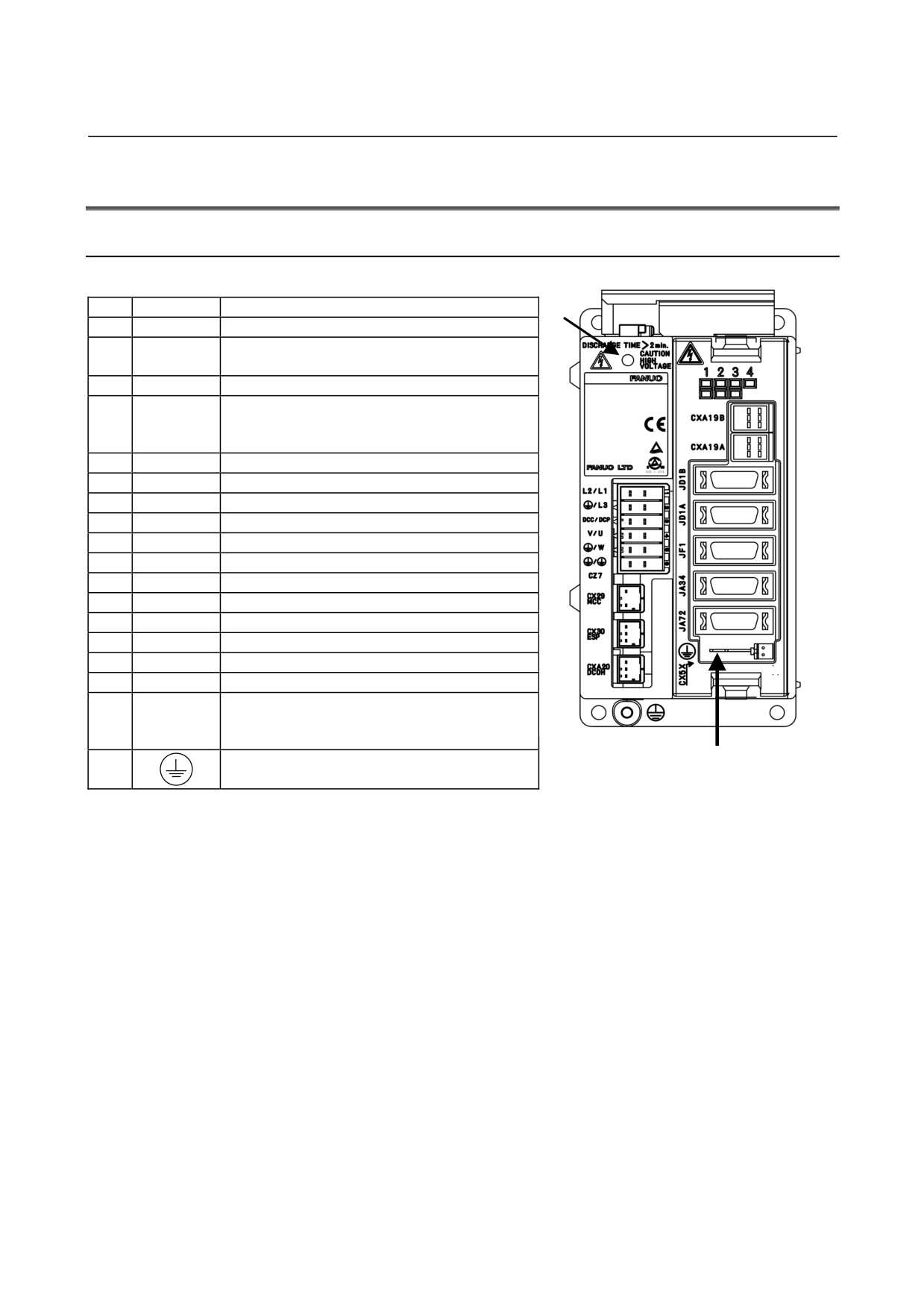
CONNECTOR LOCATION
9.2.1
SVM1-4i and SVM1-20i
No.
Name
Remarks
(1)
1
DC link charge LED
CZ7-1
2
Main power input connector
CZ7-2
3
CZ7-3
Discharge register connector
(8)
CZ7-4
(9)
4
CZ7-5
Motor power connector
(10)
CZ7-6
5
CX29
Connector for main power MCC control signal
(11)
6
CX30
ESP signal connection connector
(12)
7
CXA20
Regenerative resistor connector (for alarms)
(2)
8
LED
LED for status display
(3)
(13)
9
CXA19B
24VDC power input
(4)
10
CXA19A
24VDC power output
(14)
11
JD1B
Connector for I/O Link (to previous stage)
(5)
(15)
12
JD1A
Connector for I/O Link (to following stage)
13
JF1
Connector for Pulsecoder
(6)
(16)
14
JA34
Connector for external pulse input
15
JA72
Connector for bult-in DI
(7)
16
CX5X
Absolute Pulsecoder battery
Signal
17
grounding
Grounding terminal of control section
terminal
(18)
(17)
18
Tapped hole for grounding the flange
- 215 -
9.TOTAL CONNECTION DIAGRAM
I/O Link
B-65322EN/02
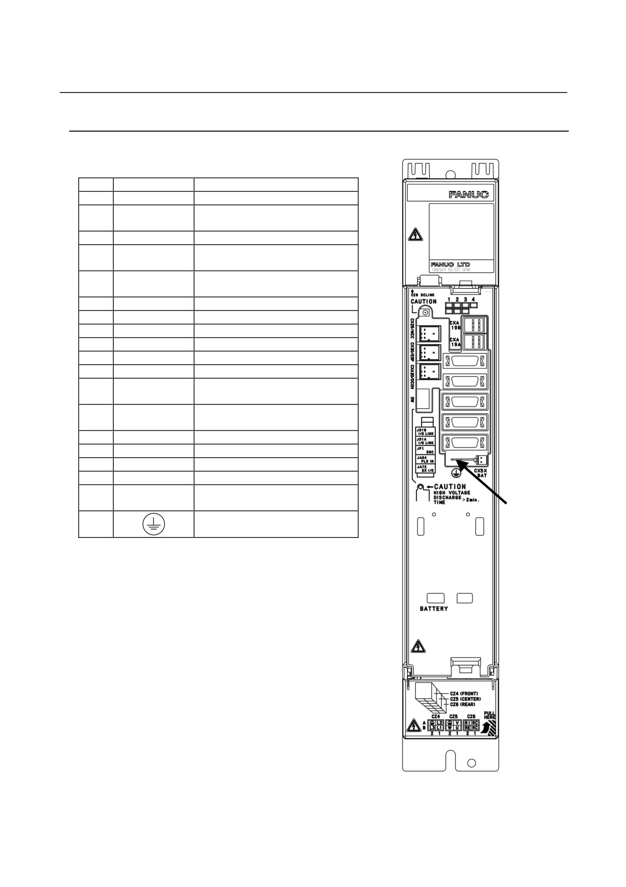
9.2.2 SVM1-40i and SVM1-80i
No.
Name
Remarks
1
DC link charge LED
Connector for main power MCC
2
CX29
control signal
3
CX30
ESP signal connection connector
Regenerative resistor connector
(for
4
CXA20
alarms)
Setting switch
5
SW
(DC alarm level)
6
CZ4
Main power input connector
(1)
(9)
7
CZ5
Motor power connector
(10)
8
CZ6
Discharge register connector
(2)
9
LED
LED for status display
(11)
(3)
10
CXA19B
24VDC power input
(12)
11
CXA19A
24VDC power output
(4)
(13)
Connector for I/O Link
(to previous
12
JD1B
stage)
(5)
(14)
Connector for I/O Link
(to following
13
JD1A
(15)
stage)
14
JF1
Connector for Pulsecoder
(16)
15
JA34
Connector for external pulse input
(17)
16
JA72
Connector for bult-in DI
17
CX5X
Absolute Pulsecoder battery
Signal grounding
18
Grounding terminal of control section
terminal
(18)
19
Tapped hole for grounding the flange
(6)
(7)
(8)
(19)
- 216 -
B-65322EN/02
I/O Link
9.TOTAL CONNECTION DIAGRAM
9.2.3
Connection Tools
See Subsection 9.2.3 “Connection Tools" in Part I.
9.2.4
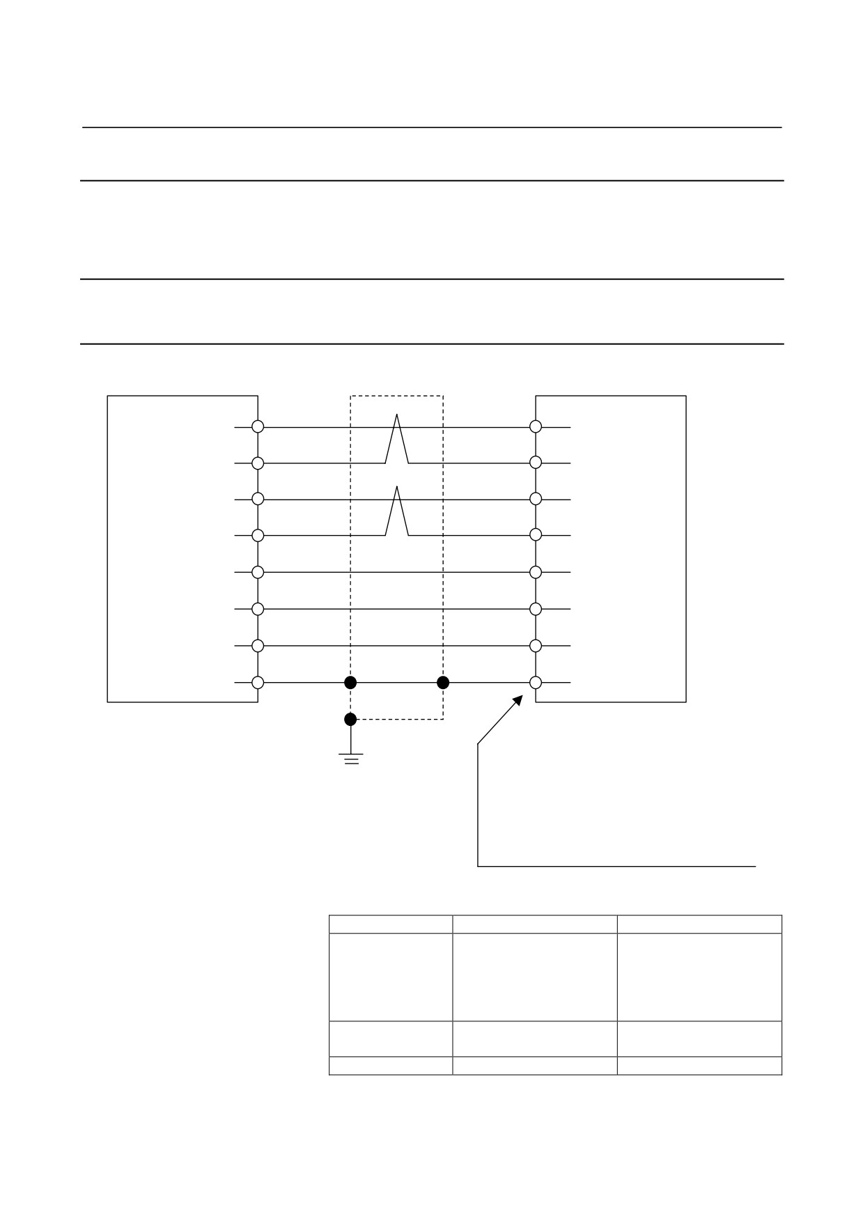
Details of Cable K1
9.2.4.1 Servo motor αi, αis series, Servo motor βis series (β0.4/5000is
to β22/2000is)
Shield
βi SVM
(1)
SD
(2)
Servo motor
(2)
*SD
(1)
(5)
REQ
(6)
(6)
*REQ
(5)
(9, 20)
5V
(8, 9)
(12, 14)
0V
(7, 10)
(7)
6V
(4)
Drain wire
(16)
FG
(3)
20-pin half-pitch connector
Connector (Japan Aviation Electronics Industry)
Grounding
JN2x S10SL1 : for φ5.7 to 7.3 sheath diameter
plate
JN2x S10SL2 : for φ6.5 to 8.0 sheath diameter
D : Straight plug
F : Angle plug
Contact (Japan Aviation Electronics Industry)
JN1-22-22S
Using cable conductor
Cable length
28 m or less
50 m or less
0.3mm2 × 5
0.5mm2 × 5
Wire construction
Wire construction
5V, 0V,6V
12/0.18 or 60/0.08
20/0.18 or 104/0.08
Insulation outer diameter
Insulation outer diameter
φ1.5 or less
φ1.5 or less
SD, *SD, REQ,
0.18mm2 or more
0.18mm2 or more
*REQ
Twisted-pair wire
Twisted-pair wire
Drain wire
0.15mm2 or more
0.15mm2 or more
* This applies also to the αMi and αCi series servo motors.
- 217 -
9.TOTAL CONNECTION DIAGRAM
I/O Link
B-65322EN/02
NOTE
1 Place the grounding plate to which the shield is
connected at a nearby position of the βi SVM to
minimize the distance between the βi SVM and the
grounding plate.
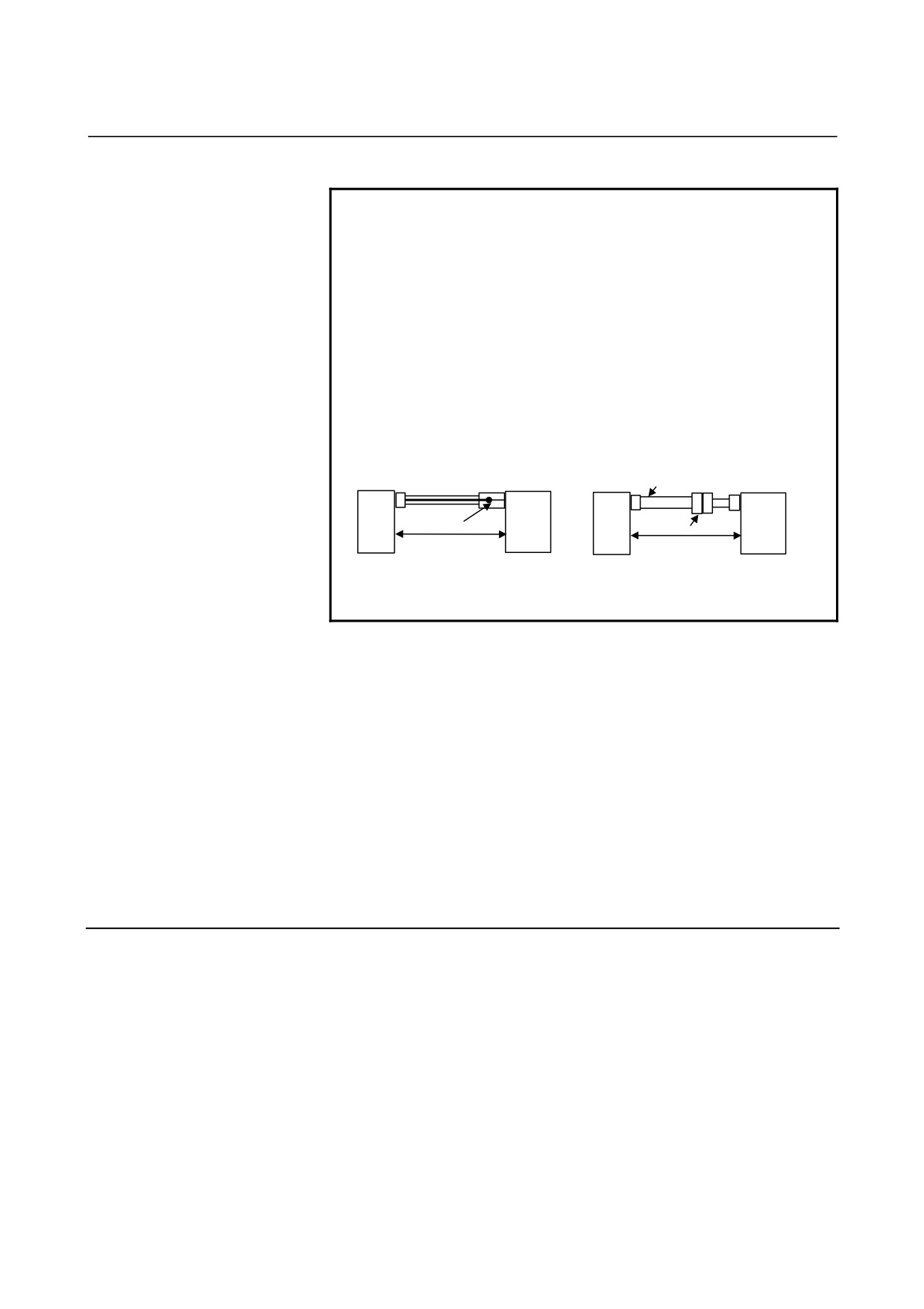
2 In case that the cable is prepared by MTB, total resistance of
5V and 0V must be less than 2Ω.
3 Pulsecoder side connector can accept maximum 0.5mm2
(wire construction 20/0.18 or 104/0.08, insulation outer
diameter φ1.5 or less) wire and sheath diameter is φ5.7 to
φ8.0. In case of using thicker wire or cable, take measures
described below.
[Case 1] Cable conductor exceeds 0.5mm2 .
[Case 2] Sheath diameter of exceeds φ8.
SVM
Servo motor
SVM
Cable thicker than φ8
Servo motor
Soldering or crimping
Connector
The total resistance (round
The total resistance (round
trip) of 5 V and 0 V must be
trip) of 5 V and 0 V must be
less than 2Ω.
less than 2Ω.
4 In case of incremental Pulsecoder, 6V is not necessary to be
connected.
• Crimp tool specification
A06B-6114-K201/JN1E : For 0.18mm2 or 0.3mm2
A06B-6114-K201/JN1D : For 0.18mm2 or 0.5mm2
• Connector kit specification
A06B-6114-K204/S : Straight plug (including a contact)
A06B-6114-K204/E : Elbow plug (including a contact)
•
Recommended cable
A66L-0001-0479 : Flexible cable 28 m or less long
A66L-0001-0488 : Flexible cable 50 m or less long
9.2.4.2 Servo motor βis series (β0.2/5000is, β0.3/5000is)
See Subsection
9.2.4.2 "Servo motor βis series
(β0.2/5000is,
β0.3/5000is)" in Part I.
- 218 -
B-65322EN/02
I/O Link
9.TOTAL CONNECTION DIAGRAM
9.2.5
Details of Cable K2
See Subsection 9.2.5 “Details of Cable K2" in Part I.
9.2.6
Details of Cable K3
See Subsection 9.2.6 “Details of Cable K3" in Part I.
9.2.7
Details of Cables K4 and K5
See Subsection 9.2.7 “Details of Cables K4 and K5" in Part I.
9.2.8
Details of Cable K6
See Subsection 9.2.8 “Details of Cable K6" in Part I.
- 219 -
9.TOTAL CONNECTION DIAGRAM
I/O Link
B-65322EN/02
9.2.9
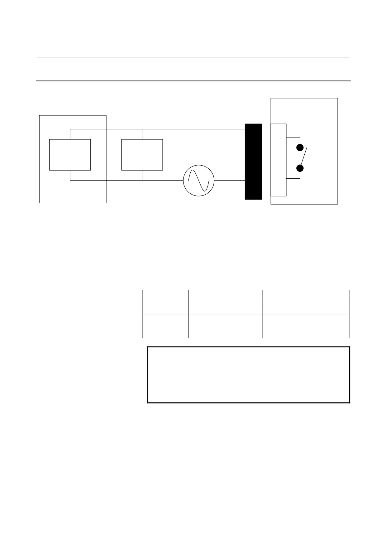
Details of Cable K7
βi SVM
MCC
CX29
1
Spark killer
Internal
Coil
contact
3
External power supply
(Use an appropriate power supply for the coil voltage
the customer uses.)
D-2000 series
Housing : 3-1318130-3
Contact : 1318107-1
Applicable wire: 0.3 to 0.85 mm2
Manufacture : Tyco Electronics AMP
For connection tools, see Subsection 9.2.3 in Part I.
Internal contact capacity
Resistance load
Inductive load
(COSφ=1)
(COSφ=0.4, L/R=15msec)
Rated load
AC250V, 3A/ DC24V, 5A
AC250V, 2A/ DC24V, 1A
Maximum
5A
5A
contact
capacity
NOTE
1 To protect the internal contact, be sure to insert a
spark killer (CR) that matches the magnetic
contactor used.
2 It is recommended that one MCC be installed per
βi SVM unit.
- 220 -
B-65322EN/02
I/O Link
9.TOTAL CONNECTION DIAGRAM
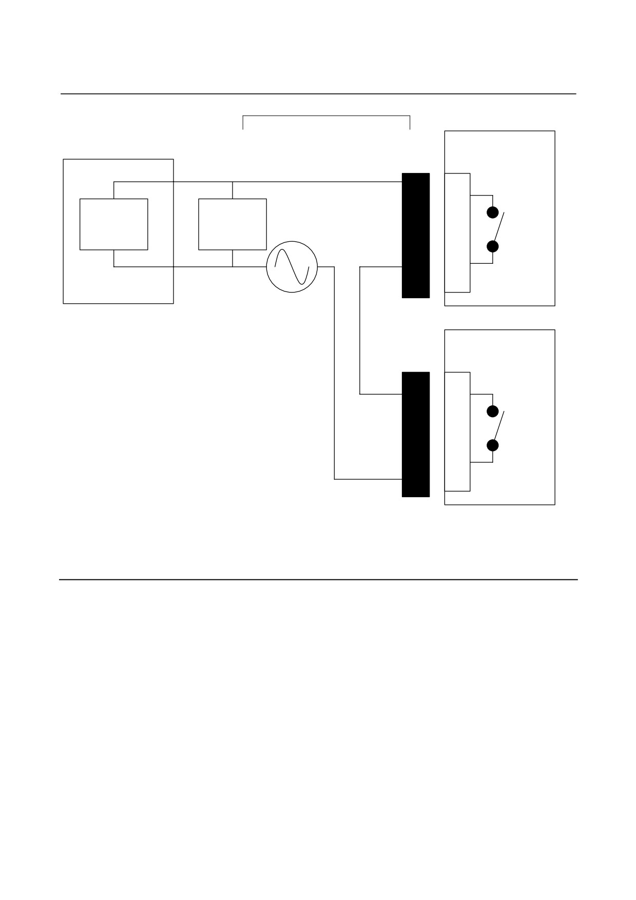
When sharing a magnetic contactor
βi SVM
MCC
CX29
1
Spark killer
Internal
Coil
contact
3
External power supply
(Use an appropriate power supply for the coil voltage
the customer uses.)
βi SVM
CX29
1
Internal
contact
3
9.2.9.1 Connection of external magnetic contactor when βi SVM
FSSB interface is used together
See Section
9.3 "HANDLING OF EXTERNAL MAGNETIC
CONTACTORS" in Part I.
- 221 -
9.TOTAL CONNECTION DIAGRAM
I/O Link
B-65322EN/02
9.2.10 Details of Cable K8
See Subsection 9.2.10 “Details of Cable K8" in Part I.
9.2.11 Details of Cable K9
See Subsection 9.2.11 “Details of Cable K9" in Part I.
9.2.12 Details of Cable K10
See Subsection 9.2.12 “Details of Cable K10" in Part I.
9.2.13 Details of Cable K11
See Subsection 9.2.13 “Details of Cable K11" in Part I.
- 222 -
B-65322EN/02
I/O Link
9.TOTAL CONNECTION DIAGRAM
9.2.14
Details of Cable K20 (Connection of FANUC I/O Link)
9.2.14.1
Overview
The FANUC I/O Link is a serial interface that connects a CNC, βi
SVM, I/O Unit-A, Power Mate CNC, and other units to transfer I/O
signals (bit data) between these units at high speed. When units are
connected by the FANUC I/O Link, one of the units serves as a master,
and the other units serve as slaves. The status of input signals from
the slaves is transferred to the master at regular intervals, and an
output signal from the master is transferred to the slaves at regular
intervals. The βi SVM can function as a slave only. It has 128
input signals and 128 output signals.
The connectors of the I/O Link are named JD1A (or JD1A1) and
JD1B, which are common to all units having the I/O Link function.
Every cable must be connected from JD1A (or JD1A1) to JD1B.
JD1A of the last unit is connected to nothing, so it is left open. It
need not be connected to a terminator or the like.
Electric cables or optical fiber cables are used for I/O Link connection.
In the following cases, use optical fiber cables:
• The cable length is 10 m or longer. When units are located
within the same cabinet, the cable length is 15 m or longer.
When a cable is installed in a duct, the units connected at both
ends of the cable should be assumed to be within the same
cabinet. For example, suppose that a CNC serving as the host is
placed on the operator's panel, the βi SVM is placed in the power
magnetics cabinet, and the I/O Link cable connecting these units
is passed through a duct. In this case, the CNC and βi SVM are
assumed to be within the same cabinet.
• A cable is routed between different cabinets, and it is impossible
to connect the cabinets with a 5.5-mm2 or thicker ground cable.
•
There is a possibility that a cable is affected by noise
significantly. For example, there is a strong electromagnetic
noise source such as a welding machine near the cable, or a cable
generating noise such as a power cable or a power magnetics
cable is laid in parallel to the cable over a long distance.
- 223 -
9.TOTAL CONNECTION DIAGRAM
I/O Link
B-65322EN/02
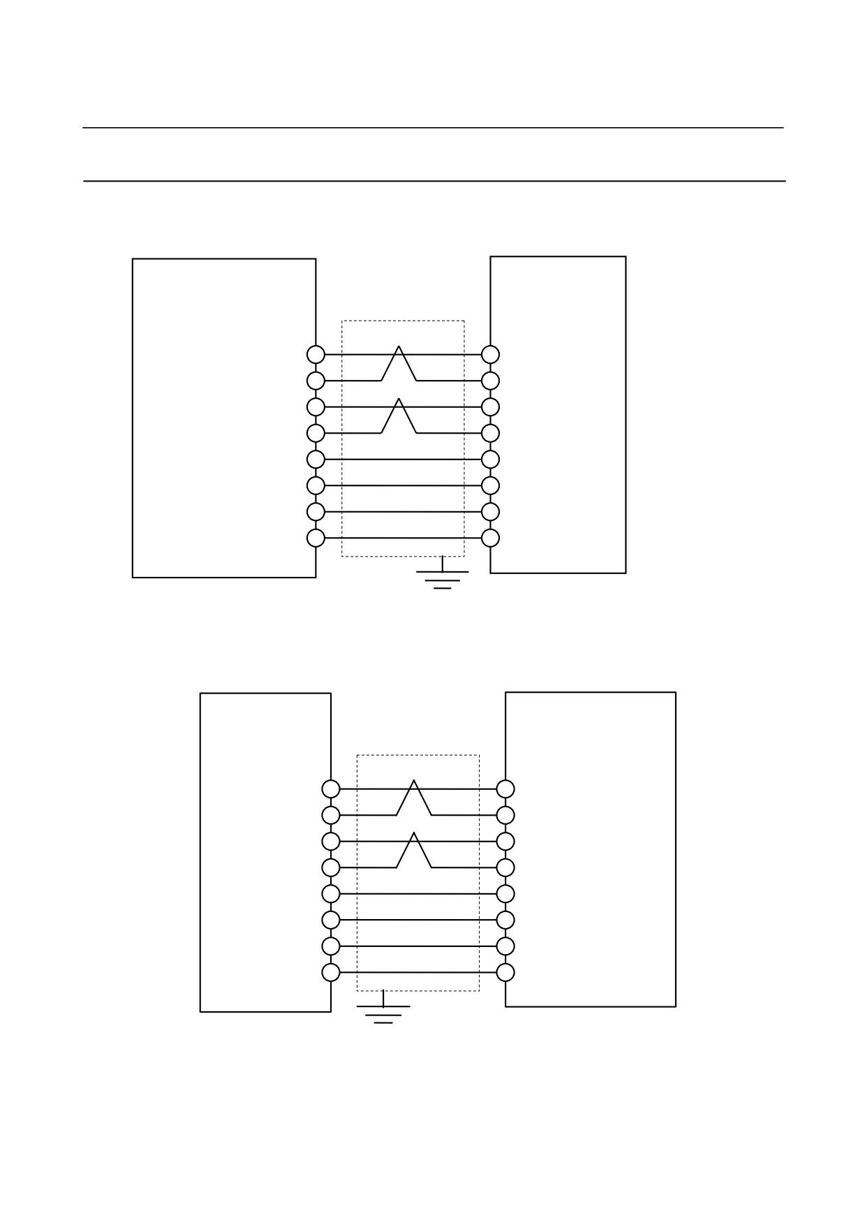
9.2.14.2 Connection of FANUC I/O Link by electric cable
Details of connection by cable K20 (when the βi SVM is connected to
the host controller or the preceding slave unit)
Host controller or preceding
βi SVM
slave unit
JD1A1/JD1
JD1B
SIN
(1)
(3) SOUT
*SIN
(2)
(4)
*SOUT
SOUT
(3)
(1) SIN
*SOUT (4)
(2)
*SIN
0V
(11)
(11)
0V
0V
(12)
(12)
0V
0V
(13)
(13)
0V
0V
(14)
(14)
0V
Details of connection by cable K20 (when connected to the following
slave unit)
When a slave unit follows, connect the unit as follows:
βi SVM
Following slave unit
SIN
(1)
(3)
SOUT
*SIN
(2)
(4)
*SOUT
SOUT
(3)
(1)
SIN
*SOUT
(4)
(2)
*SIN
0V
(11)
(11)
0V
0V
(12)
(12)
0V
0V
(13)
(13)
0V
0V
(14)
(14)
0V
- 224 -
B-65322EN/02
I/O Link
9.TOTAL CONNECTION DIAGRAM
Specifications of recommended connector and case of cable K20 on
the βi SVM side
Connector: PCR-E20FS (soldering type) (Honda Tsushin)
PCR-E20FA (crimp type)
Case: PCR-V20L
Recommended cable for cable K20
A66L-0001-0284#10P
(10 twisted pairs,
28AWG, with common
shield)
NOTE
1 Maximum cable length:
10m (when the above
recommended cable is used)
2 Be sure to use twisted pairs to connect the SIN
and *SIN signals and the SOUT and *SOUT
signals in pairs.
3 Except the pins indicated in the above figure, leave
pins open. Never connect unused conductors of
the cable to these pins.
4 Connect the shield of the cable to the ground plate
of the cabinet by using a cable clamp.
Regardless of whether the βi SVM is connected to
the host controller (or the preceding slave unit) or
the following slave unit, clamp the cable and
process the shield properly as soon as the cable is
drawn into the cabinet. When the host controller
and the βi SVM are placed in different cabinets,
shield processing must be performed in two places
for one cable. Even when the cable is not drawn
outside the cabinet, it must be clamped for shield
processing in at least one place.
9.2.14.3 Connection of FANUC I/O Link by optical fiber cable
When an optical I/O Link adapter is used, FANUC I/O Link can be
extended to up to 200 m by using optical fiber cables.
For details, refer to the manual on the host controller.
- 225 -
9.TOTAL CONNECTION DIAGRAM
I/O Link
B-65322EN/02
9.2.15
Details of Cable K21 (Internal DI Connection)
9.2.15.1
Signals
The βi SVM has five DI signals. For the connection of the
emergency stop signal, see Subsection 9.2.10, "Details of Cable K8"
and Subsection 9.2.8, "Details of Cable K6". The other four DI
signals are explained below.
(1)
*+OT:
A + overtravel signal input.
When this signal is set to "logic 0", movement in the positive
direction is disabled.
Use of this signal can be suppressed by parameter setting.
(2)
*-OT:
A - overtravel signal input.
When this signal is set to "logic 0", movement in the negative
direction is disabled.
Use of this signal can be suppressed by parameter setting.
(3)
*RILK (*DEC):
An interlock signal input (*RILK) or a reference position return
deceleration signal input
(*DEC). One of these functions is
selected by parameter setting. When the interlock signal input
(*RILK) is selected, setting this signal to "logic 0" decelerates
then stops axis movement operation. Setting this signal to
"logic 1" resumes the operation. When the reference position
return deceleration signal input (*DEC) is selected, setting this
signal to "logic 0" decelerates the feedrate, then feed operation
continues at a constant low feedrate. If the signal is then set to
"logic 1", the feed operation stops as an electrical grid position is
encountered.
(4)
HDI:
Skip signal input.
The currently executed block is skipped at the rising edge or
falling edge of this signal. Whether to use the rising edge or
falling edge of the signal is determined by parameter setting.
- 226 -
B-65322EN/02
I/O Link
9.TOTAL CONNECTION DIAGRAM
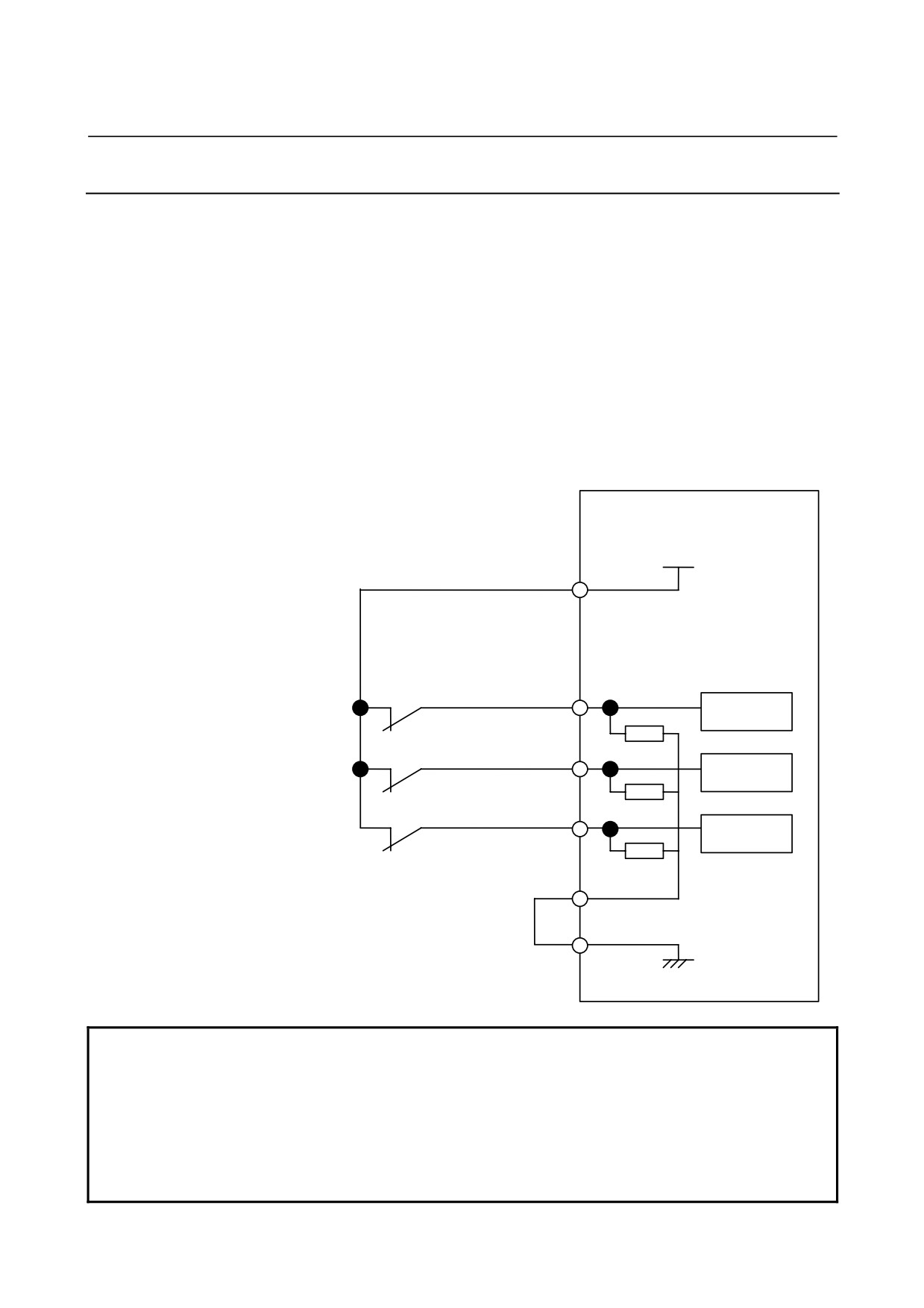
9.2.15.2
*+OT, *-OT, and *RILK(*DEC)
Input signal specifications
The receiving circuit has a non-insulating interface that can switch
between the sink type (24 V common) and the source type (0 V
common). Safety standards require use of the sink type.
The contacts on the machine side must satisfy the following:
Contact capacity:
30 VDC, 16 mA or more
Leak current between contact points when a contact is closed:
1 mA or less (voltage:
26.4 V)
Voltage drop between contact points when a contact is closed:
2 V or less (current:
8.5 mA, including voltage drop in cable)
Signal connection to power magnetics cabinet
βi SVM
JA72
+24V
(10),(19)
Interlock signal input (reference position
return deceleration signal input)
*RILK
(6)
Filter and
receiver
+ overtravel signal
input
(7)
*+OT
Filter and
receiver
- overtravel signal
input
*-OT
(8)
Filter and
receiver
(11)
DIC
0V
(12), (14), (16)
NOTE
1 Use a common shield cable as cable K21.
2 For 0V, +24V, and DIC, wires of at least 7/0.18 (0.18mm2) must be used.
3 Except the pins indicated in the above figure, leave pins open. Never connect
unused conductors of the cable to these pins.
4 The above shows an example of the 24 V common type.
When the 0 V common type is used, connect DIC (JA72-11) to +24V (JA72-10, and
19), and the later stage of each switch to 0V (JA72-12, 14, and 16).
- 227 -
9.TOTAL CONNECTION DIAGRAM
I/O Link
B-65322EN/02
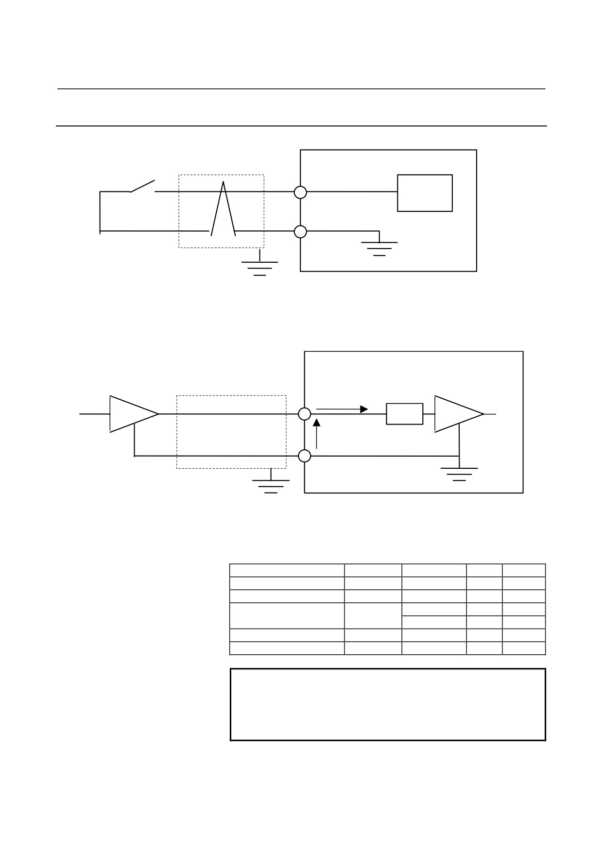
9.2.15.3 Skip signal interface
βi SVM
JA72
Receiver
HDI
(15)
0V
(12,14,16)
Input signal specifications
- Circuit configuration
βi SVM
Shield
Driver
Filter
Receiver
IiH / IiL
VH / VL
- Maximum absolute rating
Input voltage range Vin:
-3.6 V to +13.6 V
- Input characteristics
Item
Signal
Specification
Unit
Remarks
High level input voltage
VH
3.6-11.6
V
Low level input voltage
VL
0-0.55
V
2 max
MA
Vin=5V
High level input current
IiH
11 max
MA
Vin=10V
Low level input current
IiL
-8.0 max
MA
Vin=0V
Input signal pulse width
20 min
µs
NOTE
The positive sign (+) of IiH/IiL indicates the
direction in which current flows into the receiver,
and the negative sign (-) indicates the direction in
which current flows out of the receiver.
- 228 -