FANUC Series 0i-MODEL C, Series 0i Mate-MODEL C. PARAMETER MANUAL (B-64120EN/01) - page 8

4.DESCRIPTION OF PARAMETERS
B-64120EN/01
3770
Axis as the calculation reference in constant surface speed control
[Data type] Byte
[Valid data range]
0, 1, ..., number of control axes
Set the axis as the calculation reference in constant surface speed
control.
NOTE
When 0 is set, constant surface speed control is
always applied to the X-axis. In this case,
specifying P in a G96 block has no effect on the
constant surface speed control.
3771
Minimum spindle speed in constant surface speed control mode (G96)
[Data type]
2-word
[Unit of data] min-1
[Valid data range]
0 to 32767
Set the minimum spindle speed in the constant surface speed
control mode (G96).
The spindle speed in constant surface speed control is clamped to the
speed given by parameter 3771.
- 202 -
B-64120EN/01
4.DESCRIPTION OF PARAMETERS
3772
Maximum spindle speed
[Data type]
2-word
[Unit of data]
min-1
[Valid data range]
0 to 32767
This parameter sets the maximum spindle speed.
When a command specifying a speed exceeding the maximum speed
of the spindle is specified , or the speed of the spindle exceeds the
maximum speed because of the spindle speed override function, the
spindle speed is clamped at the maximum speed set in the parameter.
NOTE
1 For M series, this parameter is valid if the function
of constant surface speed control is provided or
parameter GTT (bit 4 of No. 3706) is set to 1.
2 When the constant surface speed control is
selected, the spindle speed is clamped at the
maximum speed, regardless of whether the G96
mode or G97 mode is specified.
3 When 0 is set in this parameter, the speed of the
spindle is not clamped.
4 When spindle speed command control is applied
using the PMC, this parameter has no effect, and
the spindle speed is not clamped.
5 When the multi-spindle control is selected (T
series), set the maximum speed for each spindle in
the following parameters:
Parameter No.3772:
Sets the maximum speed for the first spindle.
Parameter No.3802:
Sets the maximum speed for the second spindle.
Parameter No.3822:
Sets the maximum speed for the third spindle.
- 203 -

4.DESCRIPTION OF PARAMETERS
B-64120EN/01
P code for selecting the first spindle in multi-spindle control
3781
P code for selecting the second spindle in multi-spindle control
3782
P code for selecting the third spindle in multi-spindle control
3783
NOTE
When this parameter has been set, the power must
be turned off before operation is continued.
[Data type]
Word
[Valid data range]
0, 1 to 32767
If bit 3 (MPP) of parameter No. 3703 is set to 1, set the P code to
select each spindle under multi-spindle control. Specify the P code in
a block containing the S command.
Example)
If the P code value for selecting the second spindle is set to 3,
S1000 P3;
causes the second spindle to rotate at S1000.
NOTE
1 This parameter is valid if bit 3 (MPP) of parameter
No. 3703 is set to 1.
2 If this parameter is set to 0, the corresponding
spindle cannot be selected by a P code.
3 Identical P code values cannot be used for different
spindles.
4 If this parameter is used (bit 3 (MPP) of parameter
No. 3703 is set to 1), signals SWS1 to SWS3
<G027 bits 0 to 2> become invalid.
5 To use this parameter, the multi-spindle control
function is needed.
- 204 -
B-64120EN/01
4.DESCRIPTION OF PARAMETERS
3802
Maximum speed of the second spindle
[Data type]
2-word
[Unit of data]
min-1
[Valid data range]
0 to 32767
Parameter sets the maximum speed for the second spindle.
When a command specifying a speed exceeding the maximum speed
of the spindle is specified, or the speed of the spindle exceeds the
maximum speed because of the spindle speed override function, the
spindle speed is clamped at the maximum speed set in the parameter.
NOTE
1 This parameter is valid when the multi-spindle
control is selected.
2 When the constant surface speed control is
selected, the spindle speed is clamped to a
maximum speed, regardless of whether the G96
mode or G87 mode is set.
3 When this parameter is set to 0, parameter No.
3772 (maximum speed of the first spindle) is valid.
The spindle speed is not clamped when parameter
No. 3772 is set to 0.
4 When spindle speed command control is applied
using the PMC, this parameter has no effect, and
the spindle speed is not clamped.
3811
Maximum spindle speed for gear 1 of the second spindle
3812
Maximum spindle speed for gear 2 of the second spindle
[Data type]
2-word
[Unit of data]
min-1
[Valid data range]
0 to 32767
Set the maximum spindle speed for each gear of the second spindle.
NOTE
These parameters are used for the multi-spindle
control.
- 205 -
4.DESCRIPTION OF PARAMETERS
B-64120EN/01
3820
Data for adjusting the gain of the analog output of the third-spindle speed
[Data type]
Word
[Unit of data]
0.1%
[Valid data range]
700 to 1250
Set the data used for adjusting the gain of the analog output
of the third spindle speed.
NOTE
This parameter is used for controlling the
multi-spindles.
Offset-voltage compensation value of the analog output of the third-spindle
3821
speed
[Data type]
Word
[Unit of data]
Velo
[Valid data range]
-1024 to 1024
Set the offset-voltage compensation value of the analog output of the
third-spindle speed.
(See the description of parameter No. 3731.)
NOTE
This parameter is used for controlling the
multi-spindles.
3822
Maximum speed of the third spindle
[Data type]
Word
[Unit of data]
min-1
[Valid data range]
0 to 32767
This parameter sets the maximum speed for the third spindle.
When a command specifying a speed exceeding the maximum spindle
speed is specified, or the spindle speed exceeds the maximum speed
because of the spindle speed override function, the spindle speed is
clamped at the maximum speed set in the parameter.
- 206 -
B-64120EN/01
4.DESCRIPTION OF PARAMETERS
NOTE
1 This parameter is valid when the multi-spindle
control is selected.
2 When the constant surface speed control option is
selected, the spindle speed is clamped to a
maximum speed, regardless of whether the G96
mode or G97 mode is set.
3 When this parameter is set to 0, parameter No.
3772 (maximum speed of the first spindle) is valid.
The spindle speed is not clamped when parameter
No. 3772 is set to 0.
4 When spindle speed command control is applied
using the PMC, this parameter has no effect, and
the speed of the spindle is not clamped.
3831
Maximum spindle speed for gear 1 of the third spindle
3832
Maximum spindle speed for gear 2 of the third spindle
[Data type]
Word
[Unit of data]
min-1
[Valid data range]
0 to 32767
Set the maximum spindle speed for each gear of the third spindle.
NOTE
These parameters are used for the multi-spindle
control.
List of parameters for control of serial interface spindle Cs contouring control axis
No.
Data
Description
type
3900
Byte
First
Number of the servo axis whose loop gain is to be changed according to the set values of
group
parameters 3901 to 3904 when the Cs contouring axis is controlled (set values 0 to 8)
3901
Word
Loop gain for the servo axis when the Cs contouring axis is controlled for spindle gear 1
selection
3902
Word
Loop gain for the servo axis when the Cs contouring axis is controlled for spindle gear 2
selection
3903
Word
Loop gain for the servo axis when the Cs contouring axis is controlled for spindle gear 3
selection
3904
Word
Loop gain for the servo axis when the Cs contouring axis is controlled for spindle gear 4
selection
3910
Byte
Second
Number of the servo axis whose loop gain is to be changed according to the set values of
group
parameters 3911 to 3914 when the Cs contouring axis is controlled (set values 0 to 8)
3911
Word
Loop gain for the servo axis when the Cs contouring axis is controlled for spindle gear 1
selection
3912
Word
Loop gain for the servo axis when the Cs contouring axis is controlled for spindle gear 2
selection
3913
Word
Loop gain for the servo axis when the Cs contouring axis is controlled for spindle gear 3
selection
3914
Word
Loop gain for the servo axis when the Cs contouring axis is controlled for spindle gear 4
selection
- 207 -
4.DESCRIPTION OF PARAMETERS
B-64120EN/01
List of parameters for control of serial interface spindle Cs contouring control axis
No.
Data
Description
type
3920
Byte
Third
Number of the servo axis whose loop gain is to be changed according to the set values of
group
parameters 3921 to 3924 when the Cs contouring axis is controlled (set values 0 to 8)
3921
Word
Loop gain for the servo axis when the Cs contouring axis is controlled for spindle gear 1
selection
3922
Word
Loop gain for the servo axis when the Cs contouring axis is controlled for spindle gear 2
selection
3923
Word
Loop gain for the servo axis when the Cs contouring axis is controlled for spindle gear 3
selection
3924
Word
Loop gain for the servo axis when the Cs contouring axis is controlled for spindle gear 4
selection
<Setting method>
First, select servo axes which perform interpolation with the Cs
contouring axis. (Up to three axes can be selected.)
When there is no servo axis for interpolation with the Cs contouring
axis, set the parameters
3900, 3910, and 3920 to 0 to terminate
parameter setting.
When there are servo axes for interpolation with the Cs contouring
axis, the parameters must be set according to the procedure below for
each axis.
(1) Set the number of a servo axis (1 to 4) for interpolation with the
Cs contouring axis in parameters 39n0 (n = 0, 1, and 2).
(2) Set loop gain values of the servo axis specified in (1) above
which is used when the Cs contouring axis is controlled in
parameters 39n1, 39n2, 39n3, and 39n4. (There are four stages
for main gears used.)
(3) When the number of specified servo axes is less than 3, set the
remaining parameters (39n0) to 0 to terminate parameter setting.
When the number of a Cs contouring axis is set to parameter 39n0, the
parameter is assumed to be set to 0.
NOTE
1 In general, it is difficult to set a high loop gain for a spindle motor axis when
compared with a servo axis. These parameters are provided so that, by changing
the loop gain of a servo axis that requires interpolation with the Cs contour axis,
interpolation control can be exercised correctly between the Cs axis and servo axis
while the spindle exercises Cs contour control.
2 The loop gain of the servo axis is changed using the parameter settings made for a
spindle gear selected at the time of conversion from the spindle mode to the Cs
contour control mode.
In normal use, it is unlikely that the gear of the spindle is switched during Cs
contour control. However, note that if the gear of the spindle is changed during Cs
contour control, the loop gain of the servo axis is not changed.
3 Even when multiple Cs axes are used (bit 7 (CSS) of parameter No. 3704 = 1),
these parameters are shared.
- 208 -
B-64120EN/01
4.DESCRIPTION OF PARAMETERS
Parameters for Serial interface spindle or spindle
Parameters Nos. 4000 to 4539 below are basically used with the serial
spindle amplifier
(SPM). For details of these parameters, refer to
either of the following manuals and other related documents,
depending on the spindle that is actually connected.
•
FANUC AC SPINDLE MOTOR αi series Parameter Manual
(B-65280EN)
•
FANUC AC SPINDLE MOTOR α series Parameter Manual
(B-65160E)
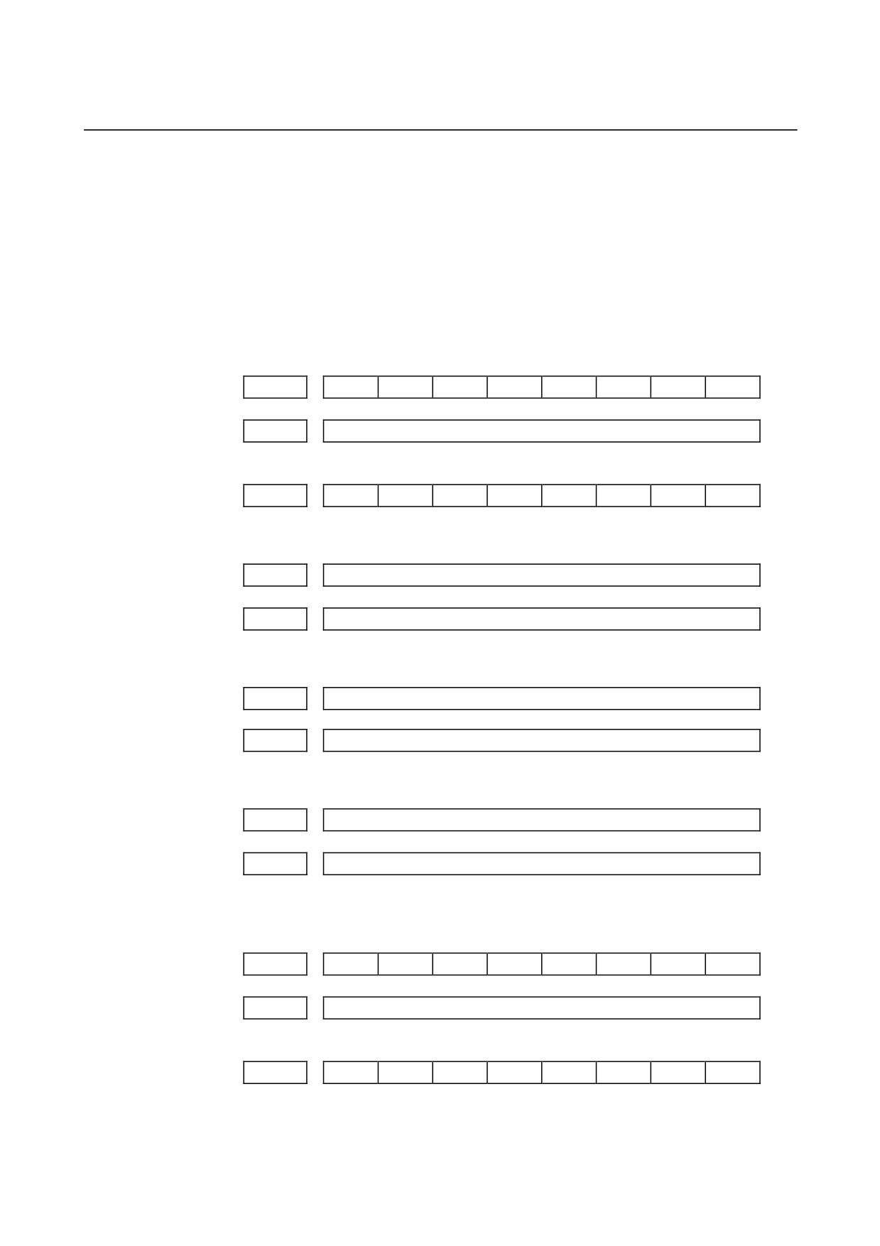
#7
#6
#5
#4
#3
#2
#1
#0
4000
:
:
4015
(No user setting allowed = Note 1)
:
:
#7
#6
#5
#4
#3
#2
#1
#0
4019
(Note 2)
[Data type]
Bit axis (spindle)
4020
:
:
4133
[Data type]
Word axis (spindle)
4134
4135
[Data type]
2-word axis (spindle)
4136
:
:
4175
[Data type]
Word axis (spindle)
#7
#6
#5
#4
#3
#2
#1
#0
4176
:
:
4191
(No user setting allowed = Note 1)
:
:
#7
#6
#5
#4
#3
#2
#1
#0
4195
(Note 2)
[Data type]
Bit axis (spindle)
- 209 -
4.DESCRIPTION OF PARAMETERS
B-64120EN/01
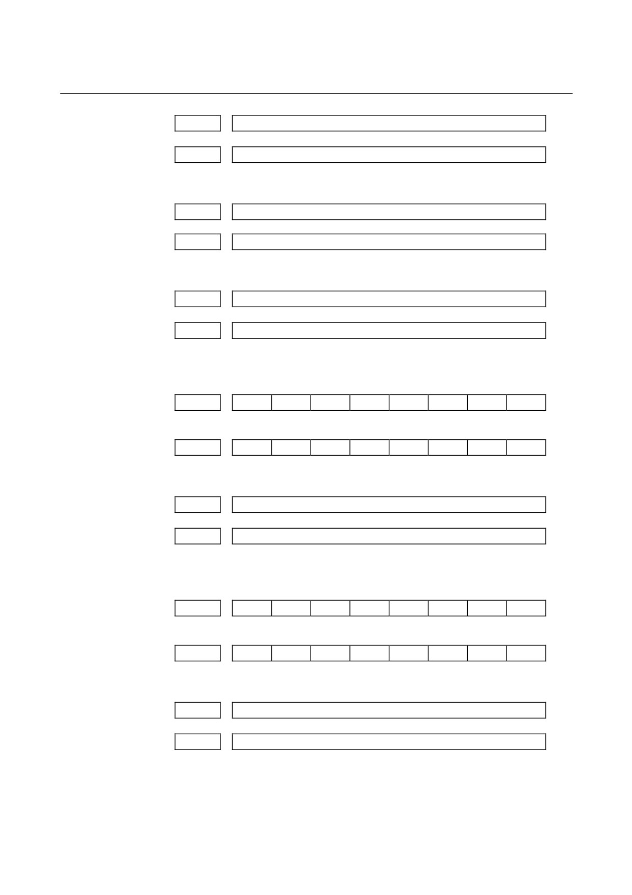
4196
:
:
4309
[Data type]
Word axis (spindle)
4310
4311
[Data type]
2-word axis (spindle)
4312
:
:
4351
[Data type]
Word axis (spindle)
#7
#6
#5
#4
#3
#2
#1
#0
4352
#7
#6
#5
#4
#3
#2
#1
#0
4353
[Data type]
Bit axis (spindle)
4354
:
:
4372
[Data type]
Word axis (spindle)
#7
#6
#5
#4
#3
#2
#1
#0
4373
#7
#6
#5
#4
#3
#2
#1
#0
4374
[Data type]
Bit axis (spindle)
4375
:
:
4393
[Data type]
Word axis (spindle)
- 210 -
B-64120EN/01
4.DESCRIPTION OF PARAMETERS
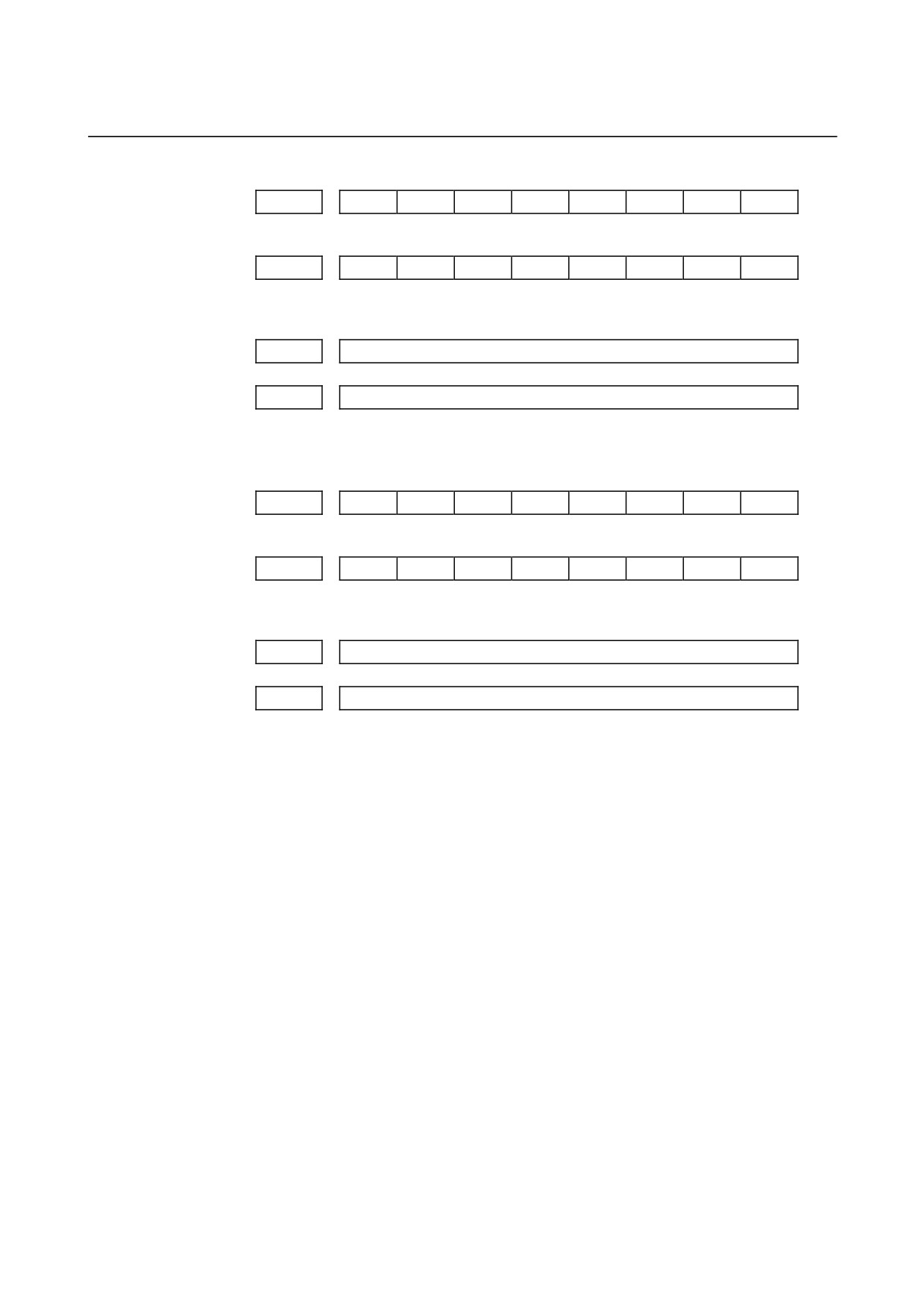
#7
#6
#5
#4
#3
#2
#1
#0
4394
#7
#6
#5
#4
#3
#2
#1
#0
4403
[Data type]
Bit axis (spindle)
4404
:
:
4466
[Data type]
Word axis (spindle)
#7
#6
#5
#4
#3
#2
#1
#0
4467
#7
#6
#5
#4
#3
#2
#1
#0
4476
[Data type]
Bit axis (spindle)
4477
:
:
4539
[Data type]
Word axis (spindle)
Notes on parameters of the spindle amplifier with the serial interface
- 211 -
4.DESCRIPTION OF PARAMETERS
B-64120EN/01
NOTE
1
Among the parameters of the spindle amplifier with the serial interface, parameters
Nos. 4015 and 4191 cannot be changed by the users.
These parameters require to assign optional software to the CNC and are
automatically set depending on the type of the software.
2
To set the parameters of the spindle amplifier with the serial interface automatically,
set #7 of parameter No.4019 (if the sub spindle is set in the CNC with the spindle
switching function, use parameter No.4195) to 1, assign the model code of the
motor to be used to parameter No.4133 (if the sub spindle is set in the CNC with
the spindle switching function, use parameter No.4309), turn off the power of the
CNC and spindle amplifier, and restart the CNC and spindle amplifier.
3
Parameters No.4000 to No.4539 are used in the processing on the spindle
amplifier. For details of these parameters, refer to either of the following manuals,
depending on the serial spindle that is actually used.
- FANUC AC SPINDLE MOTOR αi series Parameter Manual B-65280EN)
- FANUC AC SPINDLE MOTOR α series Parameter Manual B-65160E)
4
The CNC can control up to two spindle amplifiers with the serial interface.
When the spindle amplifier provides the spindle switching function, one spindle
amplifier can control two spindle motors using the switching function.
The output switching function can be used in spindle motors to be connected.
Up to four spindles, or eight types, can be used by switching the spindle motors.
(The number of spindles that can controlled simultaneously is the same as the
number of spindle amplifiers, that is two spindles.) Parameters of the spindle
amplifier with the serial interface correspond to the above functions as follows:
(1) Parameter No.4000 to No.4539 "S1": First spindle amplifier
Parameter No.4000 to No.4539 "S2": Second spindle amplifier
(2) Parameter No.4000 to No.4175 "S1"/"S2": When the spindle switching function
is not provided, or for the main spindle in the spindle amplifier when the
function is provided.
Parameter No.4176 to No.4351 "S1"/"S2": For the sub spindle in the spindle
amplifier when the spindle switching function is provided.
(3) Parameters at low speed when the output switching function is provided.
Parameters No.4136 to No.4175 "S1"/"S2": When the spindle switching
function is not provided, or for the main spindle when the function is provided.
Parameters No.4284 to No.4351 "S1"/"S2": For the sub spindle when the
spindle switching function is provided.
- 212 -
B-64120EN/01
4.DESCRIPTION OF PARAMETERS
NOTE
5
The CNC stores the parameters of the spindle amplifier with the serial interface.
The CNC sends them to the spindle amplifier at the system power on and they are
used in the unit.
These parameters are sent from the CNC to the spindle amplifier in a batch when:
- The CNC is switched on.
- The serial spindle is restarted by a reset that is carried out after spindle
communication alarm 749 occurs (because the spindle control unit is switched off
or because of noise).
If these parameters are rewritten, they are sent from the CNC to the spindle
amplifier sequentially when:
- The parameters have been entered from the MDI.
- The parameters have been entered as programmable (G10).
- The parameters have been entered via the reader/punch interface.
If bit 4 (WSP) of parameter No. 8703 is set to 0, the CNC does not immediately
perform data transfer to the spindle amplifier even when data has been written to a
parameter by using the PMC window function. So, the new parameter value set by
rewriting does not become valid automatically. To perform data transfer
immediately, set bit 4 (WSP) of parameter No. 8703 to 1.
If you want to change such parameter settings during automatic operation, use
programmable parameter input (G10).
To set parameters automatically, upload parameters corresponding to the motor
model from the spindle amplifier to the CNC prior to the procedure specified above.
The parameters of the spindle amplifier with serial interface can be changed after
the system starts. Changing the parameters (No.4000 to No.4539 "S1", "S2") in the
CNC sends them to the spindle amplifier at an appropriate time and the parameters
in the unit are updated. Be careful not to change parameters incorrectly.
- 213 -
4.DESCRIPTION OF PARAMETERS
B-64120EN/01
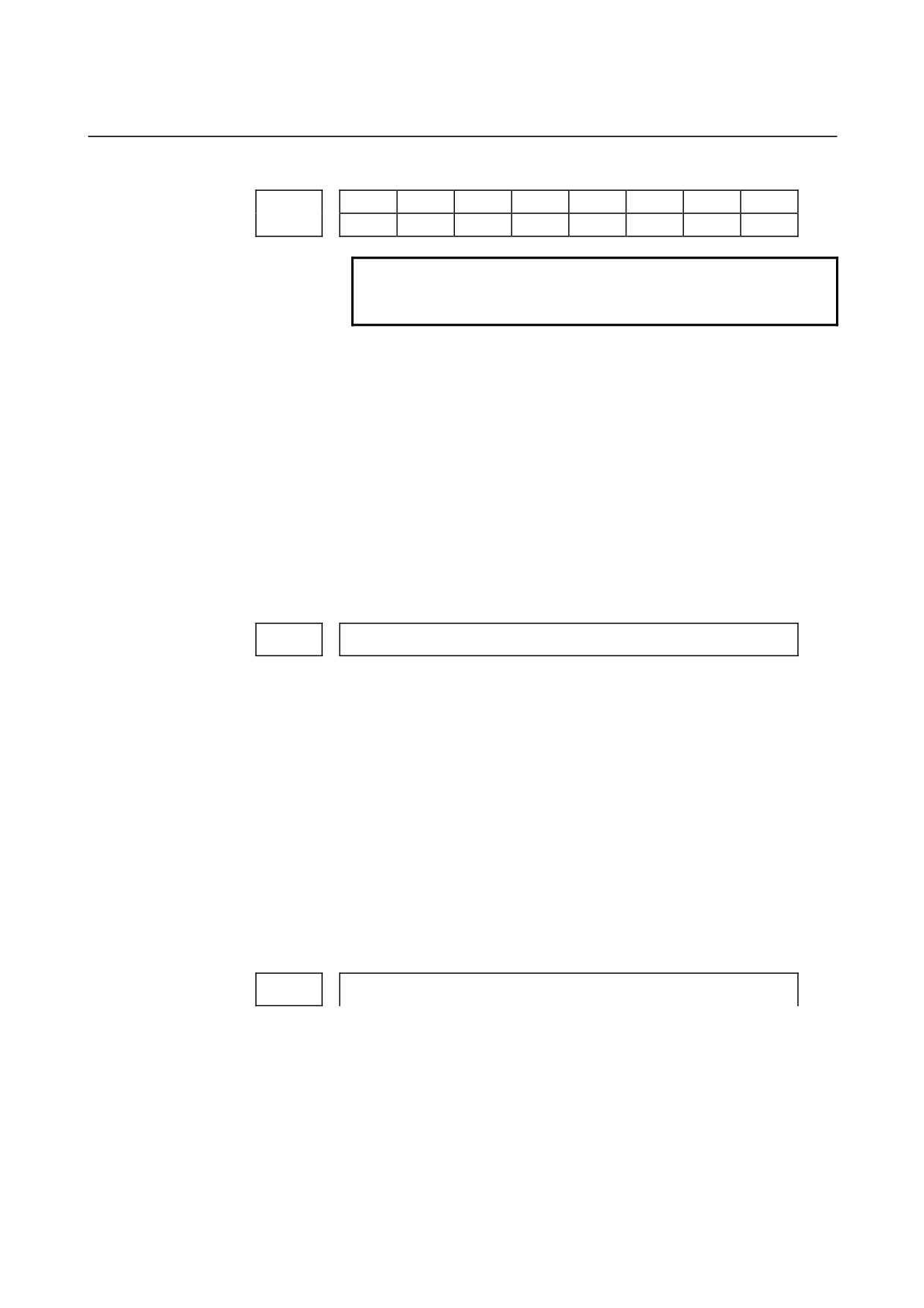
#7
#6
#5
#4
#3
#2
#1
#0
SYM
ND2
ND1
4800
ND2
ND1
NOTE
When this parameter is set, the power must be
turned off before operation is continued.
[Data type]
Bit
ND1
In controlling the spindle synchronization, the direction of the first
spindle motor rotation is:
0 : The direction indicated by the command sign
1 : The opposite direction to that indicated by the command sign
ND2
In controlling the spindle synchronization, the direction of the 2nd
spindle motor rotation is:
0 : The direction indicated by the command sign
1 : The opposite direction to that indicated by the command sign
SYM
As the maximum spindle speed in spindle synchronization control:
0 : The maximum spindle speed of the master spindle is used.
1 : The maximum spindle speed of the master spindle or slave
spindle, whichever lower, is used.
Error pulse between two spindles when synchronizing phases in the serial
4810
spindle synchronization control mode
[Data type]
Byte
[Unit of data]
Pulse
[Valid data range]
0 to 255
Set the difference in error pulses between two spindles when
synchronizing phases in the serial spindle synchronization control
mode.
When the difference in error pulse between two spindles is within the
value set in this parameter, the spindle phase synchronization
completion signal FSPPH becomes "1".
This parameter is used to check the difference in phase in
synchronization control and to confirm the completion of
synchronization in the serial spindle synchronization control mode.
For spindle synchronization, serial spindle parameters such as
parameter No. 4032 must be set.
Allowable error count for the error pulses between two spindles in the serial
4811
spindle synchronization control mode or simple synchronous control mode
[Data type] Word
[Unit of data] Pulse
[Valid data range]
0 to 32767
Set the allowable error count for the error pulses between two spindles
in the serial spindle synchronization control mode or simple
synchronous control mode.
- 214 -
B-64120EN/01
4.DESCRIPTION OF PARAMETERS
NOTE
This parameter is used to output the inter-spindle
phase error detection signal SYCAL in the serial
spindle synchronization control mode. The SYCAL
<F044#4> signal becomes "1" when a phase error
exceeding the value set in this parameter is found.
Master spindle under synchronous spindle control
4812
Slave spindle under synchronous spindle control
4813
[Data type]
Byte
[Valid data range]
0, 1, 2
Set the master spindle and slave spindle in spindle synchronization
control.
Setting value : 1 to 2, First to second spindles
NOTE
These parameters are valid only in spindle
synchronization control specified by programming.
If 0 is set, turning on spindle synchronization
control by programming (G51.8) results in an
alarm.
4831
Master axis of first spindle under synchronous spindle control
4832
Master axis of second spindle under synchronous spindle control
NOTE
When these parameters have been set, the power
must be turned off before operation is continued.
[Data type]
Byte
[Valid data range]
1 to Number of spindles
Set the slave axis and master axis of synchronous spindle control by
spindles. Set the axis number of the master axis for the axis to be
handled as the slave axis.
NOTE
This parameter is valid if bit 4 (SSS) of parameter
No. 3704 is set to 1.
- 215 -
4.DESCRIPTION OF PARAMETERS
B-64120EN/01
#7
#6
#5
#4
#3
#2
#1
#0
FLR
4900
[Data type]
Bit
FLR
When the spindle speed fluctuation detection function is used, the
rates of allowance (q) and fluctuation (r) those are set in parameter
No.4911 and No.4912, respectively are set in steps of:
0 :
1%
1 :
0.1%
Rapid (q) of the fluctuation of spindle speed which is assumed to be the
specified spindle speed
4911
[Data type]
Word
[Unit of data, valid data range]
Unit of data
1%
0. 1% (T series)
Valid data range
1 to 100
1 to 1000
NOTE
Unit of data depends on parameter No.4900#0 FLR
(T series only)
Set the ratio (q) of the spindle speed which is assumed to be the
specified spindle speed in the spindle speed fluctuation detection
function.
Let the commanded speed be Sc. When the actual spindle speed
reaches between (Sc-Sq) and (Sc + Sq), it is assumed to be the
commanded speed.
The spindle speed fluctuation detection starts.
where,
q
Sq = Sc ×
100
Spindle speed fluctuation ratio (r) for which no alarm is activated in the
spindle speed fluctuation detection function
4912
[Data type]
Word
[Unit of data, valid data range]
Unit of data
1%
0. 1% (T series)
Valid data range
1 to 100
1 to 1000
NOTE
Unit of data depends on parameter No.4900#0 FLR
(T series only).
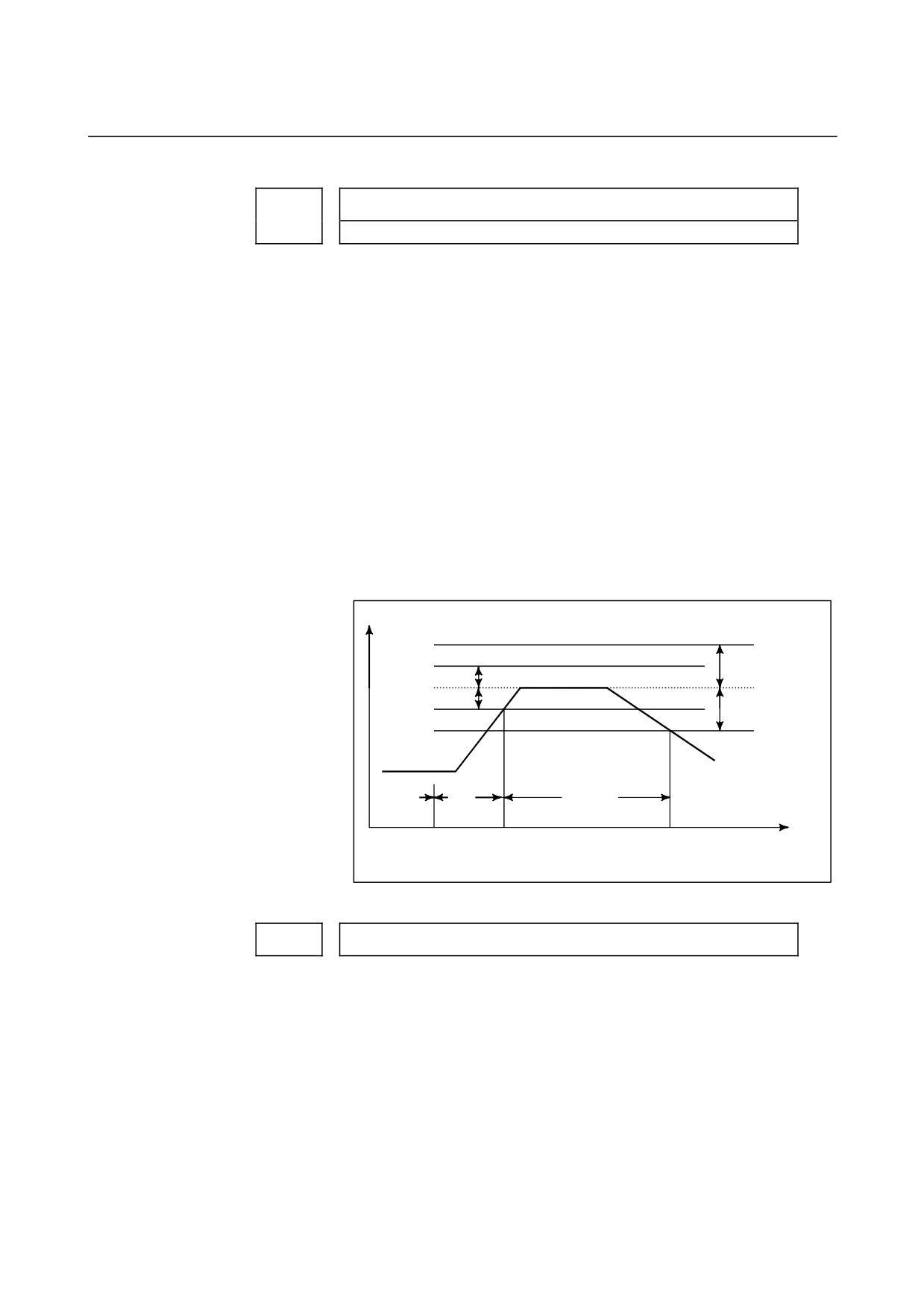
Set the spindle speed fluctuation ratio
(r) for which no alarm is
activated in the spindle speed fluctuation detection function
(see
Fig.4.20 (e)).
- 216 -
B-64120EN/01
4.DESCRIPTION OF PARAMETERS
Spindle speed fluctuation value (d) for which no alarm is activated in the
spindle speed fluctuation detection function
4913
[Data type]
Word
[Unit of data]
min-1
[Valid data range]
0 to 32767
Set the allowable fluctuation speed
(Sd) for which no alarm is
activated in the spindle speed fluctuation detection function.
The function for detecting spindle speed fluctuation checks whether
the actual speed varies for the specified speed or not. Sd or Sr,
whichever is greater, is taken as the allowable fluctuation speed (Sm).
An alarm is activated when the actual spindle speed varies for the
commanded speed (Sc) under the condition that the variation width
exceeds the allowable variation width (Sm).
Sd: The allowable constant variation width which is independent of
the specified spindle speed (Sd is set with parameter 4913.)
Sr: The allowable variation width which is obtained by multiplying
Sc (commanded spindle speed) by r (constant ratio). (r is set with
parameter 4912.)
Sm: Sd or Sr, whichever is greater
Spindle speed
Sm
Sd
Specified
Sd
speed
Sm
Actual speed
Check
No
Check
check
Time
Command
Check
Alarm
another speed start
Fig.4.20 (e) Sd and Sm
Time (p) elapsed from when the commanded spindle speed is changed to the
4914
start of spindle speed fluctuation detection
[Data type]
2-word
[Unit of data] ms
[Valid data range]
0 to 999999
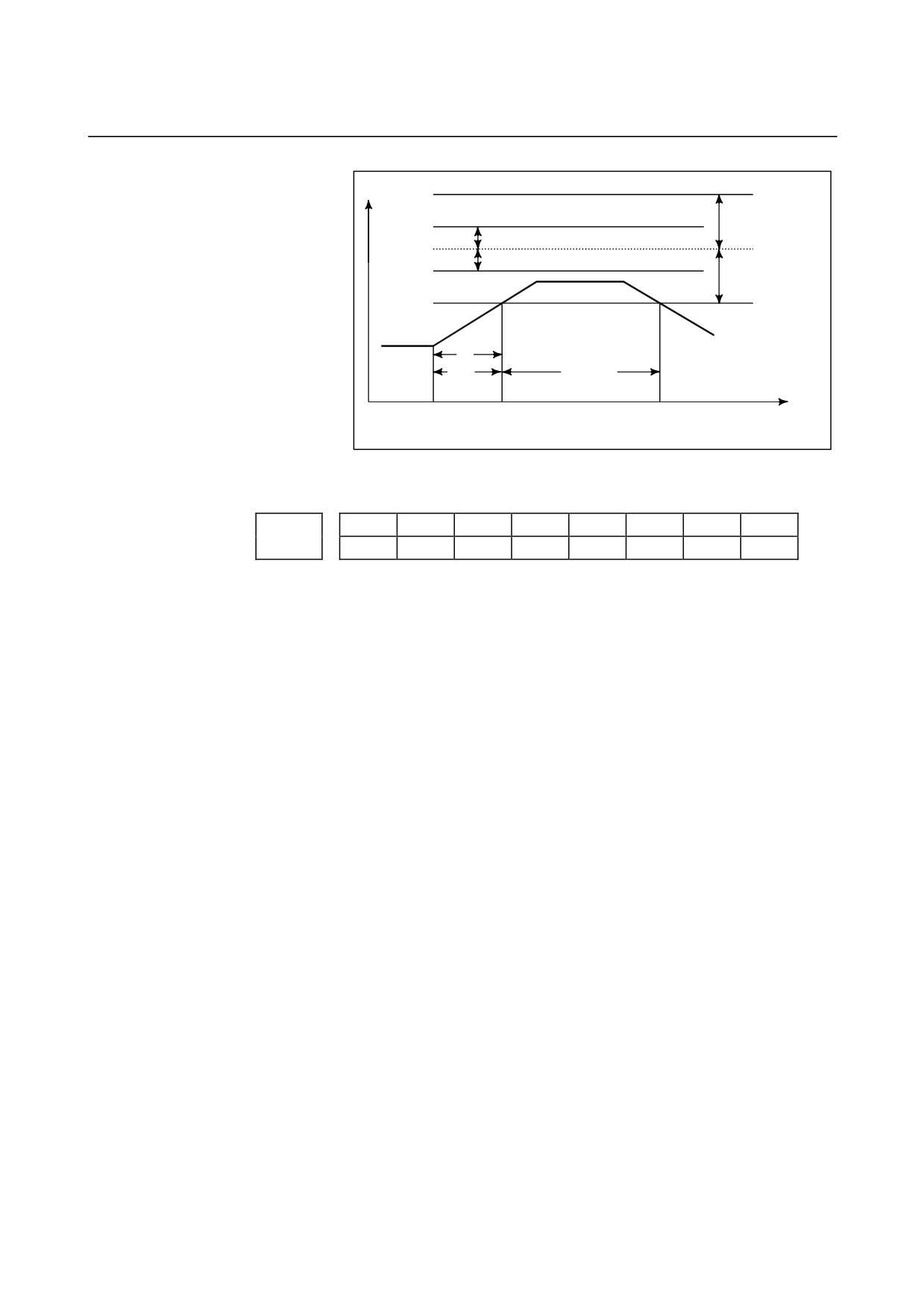
Set the time elapsed from when the specified spindle speed is changed
to the start of spindle speed fluctuation detection in the spindle speed
fluctuation detection function. That is, the fluctuation in the spindle
speed is not detected until the specified time elapses from when the
specified spindle speed is changed.
- 217 -
4.DESCRIPTION OF PARAMETERS
B-64120EN/01
Spindle speed
Sm
Sd
Specified
Sd
speed
Sm
Actual speed
P
No
Check
check
Time
Command
Check
Alarm
another speed
start
Fig.4.20 (f) Sd and Sm
#7
#6
#5
#4
#3
#2
#1
#0
IMB
ESI
TRV
ISZ
IDM
IOR
4950
[Data type]
Bit
IOR
Resetting the system in the spindle positioning mode
0 : Does not releases the mode.
1 : Releases the mode
IDM
The positioning direction for the spindle using a M code is
0 : The positive direction
1 : The negative direction
ISZ
When an M code for spindle orientation is specified in spindle
positioning:
0 : The spindle rotation mode is cleared and the mode is switched to
the spindle positioning mode, and spindle orientation operation is
performed.
1 : The spindle rotation mode is cleared and the mode is switched to
the spindle positioning mode but spindle orientation operation is
not performed.
TRV
Rotation direction of spindle positioning is set to:
0 : The positive direction
1 : The reverse direction
ESI
Selection of a spindle positioning specification
0 : The conventional specification is used.
1 : The extended specification is used.
- 218 -
B-64120EN/01
4.DESCRIPTION OF PARAMETERS
NOTE
The extended specification includes the following
two extensions:
(1) With the conventional specification, the number
of M codes for specifying a spindle positioning
angle is always 6. With the extended
specification, an arbitrary number of such M
codes from 1 to 255 can be selected by
parameter setting (See parameter No.4964.)
(2) The maximum feedrate for spindle positioning
(setting of parameter No.1420) can be
extended from 240000 to 269000 (in
increments of 10 deg/min).
IMB
When the spindle positioning function is used, half-fixed angle
positioning based on M codes uses:
0 : Specification A
1 : Specification B
NOTE
In the case of half-fixed angle positioning based on
M codes, three types of spindle positioning
operations can occur:
(1) The spindle rotation mode is cleared, then the
mode is switched to the spindle positioning
mode.
(2) Spindle positioning is performed in the spindle
positioning mode.
(3) The spindle positioning mode is cleared, then
the mode is switched to the spindle rotation
mode.
In the case of specification A:
Operations (1) to (3) are specified using separate
M codes.
(1) Specified using M codes for performing spindle
orientation. (See parameter No.4960)
(2) Specified using M codes for specifying a
spindle positioning angle. (See parameter
No.4962)
(3) Specified using M codes for clearing spindle
positioning operation. (See parameter
No.4961.)
In the case of specification B:
When M codes for specifying a spindle positioning
angle are specified, operations
(1) to (3) are performed successively. (See
parameter No.4962.)
- 219 -
4.DESCRIPTION OF PARAMETERS
B-64120EN/01
M code specifying the spindle orientation
4960
[Data type]
Word
[Unit of data]
Integer
[Valid data range]
6 to 97
Set an M code to change the spindle rotating mode to the spindle
positioning mode. Setting the M code performs the spindle orientation.
Spindle positioning can be specified from the next block.
M code releasing the spindle positioning mode
4961
[Data type]
Word
[Unit of data]
Integer
[Valid data range]
6 to 97
Set the M code to release the spindle positioning mode and
to change the mode to the spindle rotating mode.
M code for specifying a spindle positioning angle
4962
[Data type]
Word
[Unit of data]
Integer
[Valid data range]
6 to 92
Two methods are available for specifying spindle positioning. One
method uses address C for arbitrary-angle positioning. The other use
an M code for half-fixed angle positioning. This parameter sets an M
code for the latter method.
•
When bit 6 (ESI) of parameter No.4950=0
Six M code from M α to M(α+5) are used for half-fixed angle
positioning, when α is the value of this parameter.
•
When bit 6(ESI) of parameter No.4950=1
Set the start M code in this parameter, and set the number of M
codes in parameter No.4964. Suppose that the setting of
parameter No. 4962 is α and the setting of parameter No. 4964 is
β. Then β M codes from Mα to M (α+β-1) are used for half fixed
angle positioning.
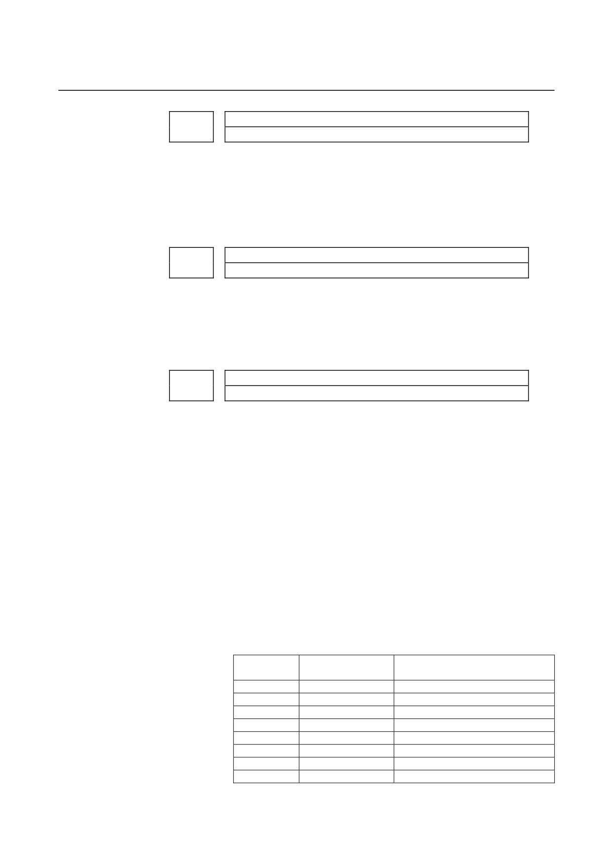
The table below indicates the relationship between the M codes and
positioning angles.
Example:
M code
Positioning angle
Positioning angle when θ = 30°
Mα
θ
30°
M (α+1)
2θ
60°
M (α+2)
3θ
90°
M (α+3)
4θ
120°
M (α+4)
5θ
150°
M (α+5)
6θ
180°
:
:
:
M (α+n)
(n+1) θ
- 220 -
B-64120EN/01
4.DESCRIPTION OF PARAMETERS
NOTE
θ represents the basic angular displacement set in
parameter No.4963.
Basic angular displacement used for spindle positioning using M code
4963
[Data type]
Word
[Unit of data]
deg
[Valid data range]
1 to 60
This parameter sets a basic angular displacement used for half-fixed
angle positioning using M codes.
Number of M codes for specifying a spindle positioning angle
4964
[Data type]
Byte
[Unit of data]
Integer
[Valid data range]
0, 1 to 255
This parameter sets the number of M codes used for Half-fixed angle
positioning using M codes.
As many M codes as the number specified in this parameter, starting
with the M code specified in parameter No.4962, are used to specify
half-fixed angle positioning.
Let α be the value of parameter No.4962, and let β be the value of
parameter No.4964. That is, M codes from Mα to M (α+β-1) are used
for half-fixed angle positioning.
NOTE
1 This parameter is valid when bit 6 (ESI) of
parameter No.4950=1.
2 Make sure that M codes from Mα to M (α+β-1) do
not duplicate other M codes.
3 Setting this parameter to 0 has the same effect as
setting 6. That is, M code from Mα to M (α+5) are
used for half-fixed angle positioning.
Servo loop gain of the spindle
4970
[Data type]
Word
[Unit of data]
0.01 s-1
[Valid data range]
1 to 9999
Set the servo loop gain of the spindle in the spindle positioning mode.
- 221 -
4.DESCRIPTION OF PARAMETERS
B-64120EN/01
Servo loop gain multiplier of the spindle for gear 1
4971
Servo loop gain multiplier of the spindle for gear 2
4972
Servo loop gain multiplier of the spindle for gear 3
4973
Servo loop gain multiplier of the spindle for gear 4
4974
[Data type]
Word
Set the servo loop gain multipliers of the spindle for gears 1 to 4.
The multipliers are used to convert the amount of the position
deviation to the voltage used in the velocity command. Assign the data
obtained from the following equation to the parameters.
Loop gain multiplier = 2048000 × E × A/L
where;
E : Voltage required to rotate the spindle motor at 1000 min-1 in the
velocity command
L : Rotation angle of the spindle per one motor rotation (normally
360)
A : Unit used for the detection (degree)
[Example]
Let E be 2.2 V, L be 360 degrees, and A be 0.088 degrees/pulse.
Loop gain multiplier = 2048000 × 2.2 × 0.088/360 = 1101
* When the voltage specified for the spindle motor is 10 V at
a spindle speed of 4500 min-1, E is regarded as 2.2 V.
NOTE
The above parameters No.4971 to No.4974 are for
analog spindles.
- 222 -

B-64120EN/01
4.DESCRIPTION OF PARAMETERS
4.21
PARAMETERS OF TOOL COMPENSATION
#7
#6
#5
#4
#3
#2
#1
#0
EVO
EVR
TAL
TLB
TLC
5001
EVO
TPH
EVR
TAL
OFH
TLB
TLC
[Data type]
Bit
TLC
Tool length compensation
0 : Tool length compensation A or B
(Conforms to TLB in
parameter No.5001)
1 : Tool length compensation C
TLB
Tool length compensation axis
0 : Always Z axis irrespective of plane specification (Tool length
compensation A)
1 : Axis perpendicular to plane specification (G17, G18, and G19)
(Tool length compensation B)
OFH
Offset number of tool length compensation, cutter compensation and
tool offset
0 : Specifies the tool length compensation using an H code, and
cutter compensation C using a D code
Tool offset conforms to TPH in parameter No.5001#5.
1 : Specifies the tool length compensation, cutter compensation and
tool offset using H codes
TAL
Tool length compensation C
0 : Generates an alarm when two or more axes are offset
1 : Not generate an alarm even if two or more axes are offset
EVR
When a tool compensation value is changed in cutter compensation C
mode:
0 : Enables the change, starting from that block where the next D or
H code is specified.
1 : Enables the change, starting from that block where buffering is
next performed.
TPH
Specifies whether address D or H is used as the address of tool offset
number (G45 to G48).
0 : D code
1 : H code
TPH is valid when OFH in parameter No.5001#2 is 0.
EVO
When in tool length compensation A or tool length compensation B,
the tool compensation amount is changed in offset mode (G43 or G44)
(for the M series) or when in tool position compensation, the
compensation amount is changed (for the T series):
0 : A block specifying the next G43, G44, or an H code and
subsequent blocks become valid. (M series)
A block specifying the next T code and subsequent blocks
become valid. (T series)
1 : A block to be buffered next and subsequent blocks become valid.
- 223 -
4.DESCRIPTION OF PARAMETERS
B-64120EN/01
#7
#6
#5
#4
#3
#2
#1
#0
WNP
LWM
LGC
LGT
LWT
LGN
LD1
5002
[Data type]
Bit
LD1
Offset number of tool offset
0 : Specified using the lower two digits of a T code
1 : Specified using the lower one digit of a T code
LGN
Geometry offset number of tool offset
0 : Is the same as wear offset number
1 : Specifies the geometry offset number by the tool selection
number
LWT
Tool wear compensation is performed by:
0 : Moving the tool.
1 : Shifting the coordinate system.
(Only when the LGT parameter (bit 4 of No.5002) is set to 0)
LGT
Tool geometry compensation
0 : Compensated by the shift of the coordinate system
(Compensation is made in the block of T code regardless of
LWM at this time.)
1 : Compensated by the tool movement
LGC
Tool geometry compensation (It is effective when LGT = 0. When
LGT is 1, it is always canceled.)
0 : Not canceled by offset number 0
1 : Canceled by offset number 0
LWM
Tool offset (Geometry and wear compensation when LGT = 1.)
0 : Is done in the T code block
1 : Is done together with the axis movement
NOTE
When LGT = 0, the offset is done in a T code block
regardless of this parameter.
WNP
Imaginary tool tip direction used for tool nose radius compensation, is
the direction specified by:
0 : Geometry offset number
1 : Wear offset number
#7
#6
#5
#4
#3
#2
#1
#0
TGC
LVC
CCN
5003
LVK
CCN
SUV
SUP
[Data type]
Bit
SUP
Start up or cancel in cutter compensation C or cutter compensation for
5-axis machining
0 : Type A
1 : Type B
SUV
Startup or cancellation of cutter compensation C is:
0 : Type A or type B. (The setting of bit 0 (SUP) of parameter No.
5003 is followed.)
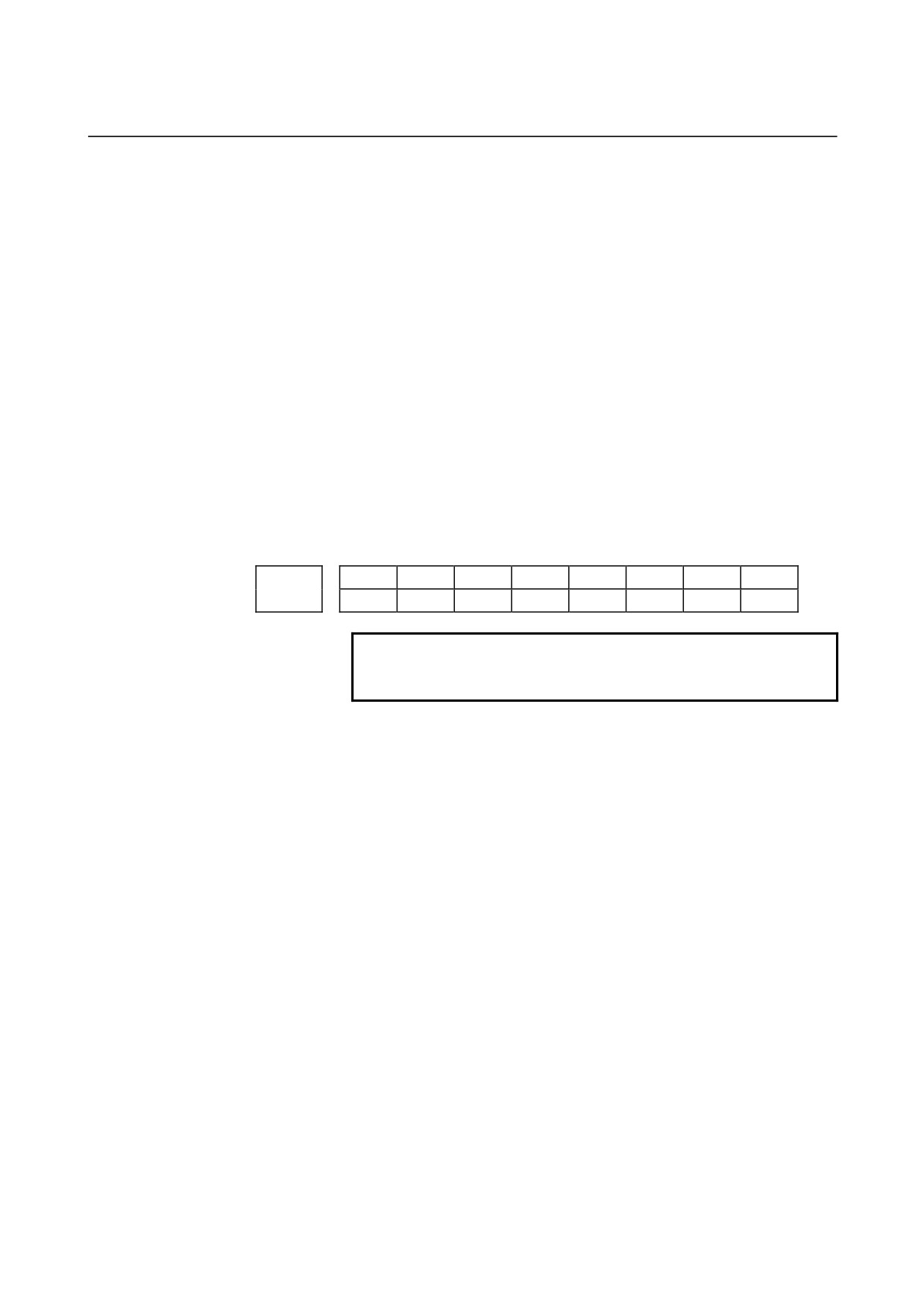
1 : Perpendicular to the next movement.
- 224 -
B-64120EN/01
4.DESCRIPTION OF PARAMETERS
CCN
When automatic reference position return (G28) is specified in the
cutter compensation C mode
(M series) or in tool nose radius
compensation (T series):
0 : The cutter compensation or tool nose radius compensation vector
is cancelled in movement to an intermediate position.
1 : The cutter compensation or tool nose radius compensation vector
is not cancelled in movement to an intermediate position, but is
cancelled in movement to the reference position.
LVC
Offset value of tool offset
0 : Not cleared, but held by reset
1 : Cleared by reset
LVK
Tool length offset value
0 : Cleared by reset
1 : Not cleared, but held by reset
TGC
Tool geometry compensation value
0 : Not canceled by reset
1 : Canceled by reset
(Valid when LVC, #6 of parameter No.5003, is "1")
#7
#6
#5
#4
#3
#2
#1
#0
Y03
TS1
ORC
5004
ODI
NOTE
When this parameter is set, the power must be
turned off before operation is continued.
[Data type]
Bit
ORC
Tool offset value
0 : Set by the diameter specification
(Can be set in only the axis under diameter programming)
1 : Set by the radius specification
ODI
A cutter compensation amount is set using:
0 : A radius.
1 : A diameter.
TS1
When the tool offset measurement value direct input B function is
used, touch sensor contact detection is based on:
0 : Four-contact input.
1 : One-contact input.
Y03
Y axis offset is :
0 : Used for 4th axis.
1 : Used for 3rd axis.
- 225 -
4.DESCRIPTION OF PARAMETERS
B-64120EN/01
#7
#6
#5
#4
#3
#2
#1
#0
TLE
QNI
PRC
CNI
5005
[Data type]
Bit
CNI
On the offset screen, Y-axis offset screen, and macro screen, the
[INP.C] soft key is:
0: Used.
1: Not used.
(The [INP.C] soft key is not displayed.)
PRC
Direct input of tool offset value and workpiece coordinate-system
shift value
0 : Not use a PRC signal
1 : Uses a PRC signal
QNI
In the function of input of offset value measured B
0 : Not automatically select the tool offset number
1 : Automatically selects a tool offset number
TLE
When the tool offset measurement value direct input B function is
used, a tool offset value, set by the offset write signal, is:
0 : Always received in offset write mode.
1 : Received only in offset write mode and during movement along
an axis (where "during movement along an axis" means that the
positional deviation value is other than 0).
#7
#6
#5
#4
#3
#2
#1
#0
TGC
OIM
5006
TOS
TCE
OIM
[Data type]
Bit
OIM
When the unit is switched between the inch and metric systems,
automatic tool offset value conversion is:
0 : Not performed
1 : Performed
NOTE
If this parameter setting is changed, reset the tool
offset data.
TGC
When a T code is specified in a block containing G50, G04, or G10:
0 : No alarm occurs.
1 : P/S alarm No.245 occurs.
TCE
When a tool length offset is specified in a rigid tapping or drilling
canned cycle, the axis to which the tool length offset applies is:
0 : Determined according to the specifications of tool length offset
C.
1 : The drilling axis.
NOTE
This parameter is valid when tool length offset C is
selected (bit 0 (TLC) of parameter No. 5001 = 1).
- 226 -
B-64120EN/01
4.DESCRIPTION OF PARAMETERS
TOS
The operation of tool length compensation is set as follows:
0 : Tool length compensation is performed by axis movement.
1 : Tool length compensation is performed by shifting the coordinate
system.
#7
#6
#5
#4
#3
#2
#1
#0
QCR
MCR
CNV
CNC
CNI
5008
GCS
QCR
MCR
CNV
G39
CNC
CNI
[Data type]
Bit
CNI
Interference check for cutter compensation C (M series) or tool nose
radius compensation (T series) is:
0 : Performed
1 : Not performed
CNC
During interference check for cutter compensation C (M series) or tool
nose radius compensation (T series), when the direction of movement
after application of the offset differs from the programmed direction
by between
90° and 270°:
0 : An alarm is issued.
1 : No alarm is issued.
G39
The corner rounding function (G39) in cutter compensation C mode
is:
0 : Disabled.
1 : Enabled.
CNV
The interference check and vector erasure of cutter compensation C
(M series) or tool nose radius compensation (T series) are:
0 : Performed.
1 : Not performed.
MCR
If G41/G42 (cutter compensation C (M series) or tool nose radius
compensation (T series)) is specified in the MDI mode, an alarm is:
0 : Not raised.
1 : Raised. (P/S5257)
NOTE
In the MDI mode, cutter compensation C (M series)
or tool nose radius compensation (T series) is not
performed, irrespective of the setting of this
parameter.
QCR
The travel distance of circular interpolation in cutter compensation C
(M series) or tool nose radius compensation (T series) is judged:
0 : In the FS0(FS16) format.
1 : In the FS15 format.
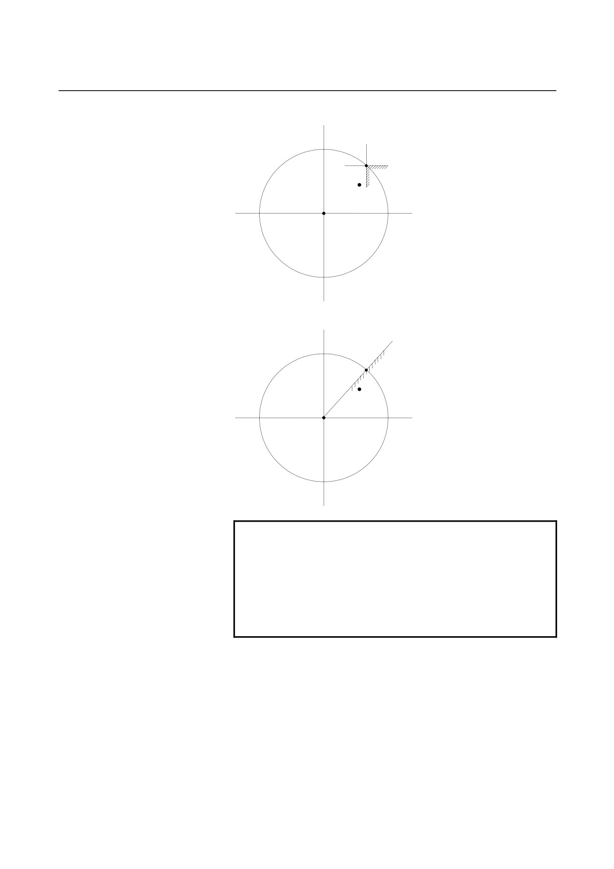
FS0(FS16) and FS15 determine the travel distance in different ways if
the radius of arc at the start point of circular interpolation is different
from that at the end point (if the end point is not on the arc). By this
parameter, the method of determining the travel distance of circular
interpolation can be selected.
- 227 -
4.DESCRIPTION OF PARAMETERS
B-64120EN/01
[FS0(FS16) format]
C
Start point
D
A
End point
Center
If the end point viewed from the start point
is in the A region, the movement is made
along the shortcut. If the end point is in the
B, C, or D region, almost a single turn is
made.
[FS15 format]
Start point
A
End point
Center
If the end point is in the A region separated
by the line L drawn between the start point
and the center, the movement is made
along the shortcut. If the end point is in the
B region, almost a single turn is made.
NOTE
The setting of this parameter determines the travel
distance determination method for circular
interpolation not during cutter compensation C (M
series) or tool nose radius compensation (T series)
as well. Accordingly, if this parameter is set, the
setting of bit 3 (CQD) of parameter No. 3450 is
invalid.
GCS If G49 (G code for canceling tool length compensation) and G40 (G
code for canceling cutter compensation) are specified in a single block,
the tool length compensation is cancelled:
0 : In the next block.
1 : In the specified block.
- 228 -
B-64120EN/01
4.DESCRIPTION OF PARAMETERS
#7
#6
#5
#4
#3
#2
#1
#0
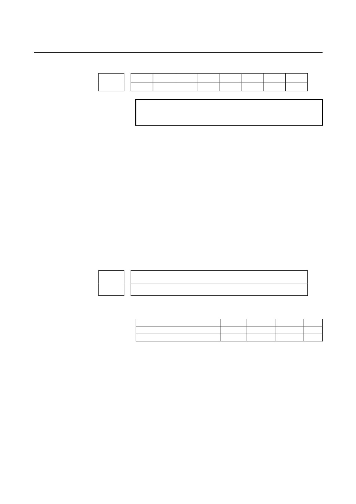
NTT
TSD
QSA
GSG
5009
NOTE
When this parameter has been set, the power must
be turned off before operation is continued.
[Data type]
Bit
GSG
In the mode of tool compensation direct input B, the offset write input
signal is input:
0 : From the machine side. <G004 bits 2 to 5>
1 : From the PMC side. <G132 bits 0 and 1, G134 bits 0 and 1>
QSA
The angular axis control function is:
0 : Not supported by the tool compensation direct input B function.
1 : Supported by the tool compensation direct input B function.
TSD
In the tool compensation direct input B function, the error prevention
function is:
0 : Disabled.
1 : Enabled.
NTT
When a shift type tool offset is applied during simplified
synchronization control, and the master spindle and slave spindle are
not related to the tool offset:
0 : An alarm is issued. (P/S alarm 214)
1 : No alarm is issued.
Limit value that ignores the vector when a tool moves on the outside of a
corner during tool nose radius compensation
5010
Limit value that ignores the vector when a tool moves on the outside of a
corner during cutter compensation C
[Data type]
Word
[Unit of data]
Input increment
IS-A
IS-B
IS-C
Unit
Millimeter input
0.01
0.001
0.0001
mm
Inch input
0.001
0.0001
0.00001
inch
[Valid data range]
0 to 16383
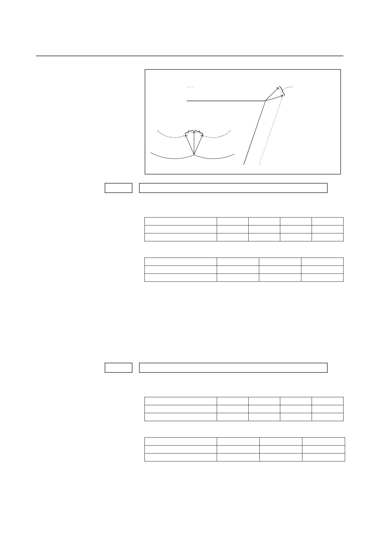
This parameter sets the limit value that ignores a slight movement
occurring when a tool moves on the outside of the corner during tool
nose radius compensation (T series) or cutter compensation C (M
series).
- 229 -
4.DESCRIPTION OF PARAMETERS
B-64120EN/01
Actual tool path
Very small amount
of travel to be
ignored
Programmed path
Very small amount of travel to be
ignored
5013
Maximum value of tool wear compensation
[Data type]
2-word
[Unit of data]
Input increment
IS-A
IS-B
IS-C
Unit
Millimeter input
0.01
0.001
0.0001
mm
Inch input
0.001
0.0001
0.00001
inch
[Valid data range]
Input increment
IS-A
IS-B
IS-C
Millimeter input
0 to 99999
0 to 999999
0 to 9999999
Inch input
0 to 99999
0 to 999999
0 to 9999999
This parameter sets the maximum allowable tool wear compensation
value. If an attempt is made to set a tool wear compensation value, the
absolute value of which exceeds the value set in this parameter, the
following alarm or warning is output:
Input from MDI
Warning: Too many digits
Input by G10
P/S alarm No.032: Offset value is out of range by G10.
5014
Maximum value of incremental input for tool wear compensation
[Data type]
2-word
[Unit of data]
Input increment
IS-A
IS-B
IS-C
Unit
Millimeter input
0.01
0.001
0.0001
mm
Inch input
0.001
0.0001
0.00001
inch
[Valid data range]
Input increment
IS-A
IS-B
IS-C
Millimeter input
0 to 99999
0 to 999999
0 to 9999999
Inch input
0 to 99999
0 to 999999
0 to 9999999
- 230 -
B-64120EN/01
4.DESCRIPTION OF PARAMETERS
Set the maximum allowable value for the tool wear compensation
value, input as an incremental value. If the incremental input value
(absolute value) exceeds the set value, the following alarm or warning
message is output:
Input from MDI
Warning: Setting value out of range.
Input using G10
P/S alarm No.032: Offset value is out of range by G10.
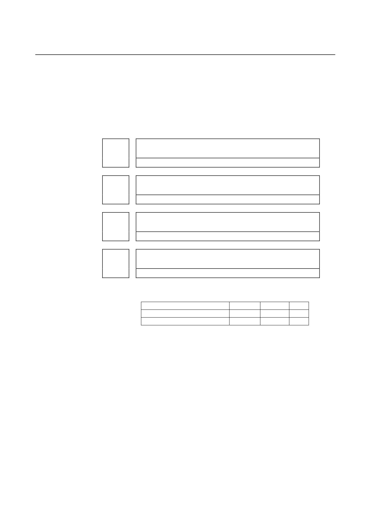
Distance (XP) between reference position and X axis + contact surface
Distance (X1P) between reference position and X axis + contact surface of
5015
touch sensor 1
Distance (XM) between reference position and X axis - contact surface
Distance (X1M) between reference position and X axis - contact surface of
5016
touch sensor 1
Distance (ZP) between reference position and Z axis + contact surface
Distance (Z1P) between reference position and Z axis + contact surface of
5017
touch sensor 1
Distance (ZM) between reference position and Z axis - contact surface
Distance (Z1M) between reference position and Z axis - contact surface of
5018
touch sensor 1
[Data type]
2-word
[Unit of data]
Input increment
IS-B
IS-C
Unit
Millimeter input
0.001
0.0001
mm
Inch input
0.0001
0.00001
inch
[Valid data range]
-99999999 to 99999999
These parameters are related to the function of input of tool offset
value measured B.
They set the distance (with sign) between the measurement reference
position and sensor contact surface. For an axis under diameter
programming, set it by a diameter value.
- 231 -