FANUC Series 0i-MODEL C, Series 0i Mate-MODEL C. PARAMETER MANUAL (B-64120EN/01) - page 7
4.DESCRIPTION OF PARAMETERS
B-64120EN/01
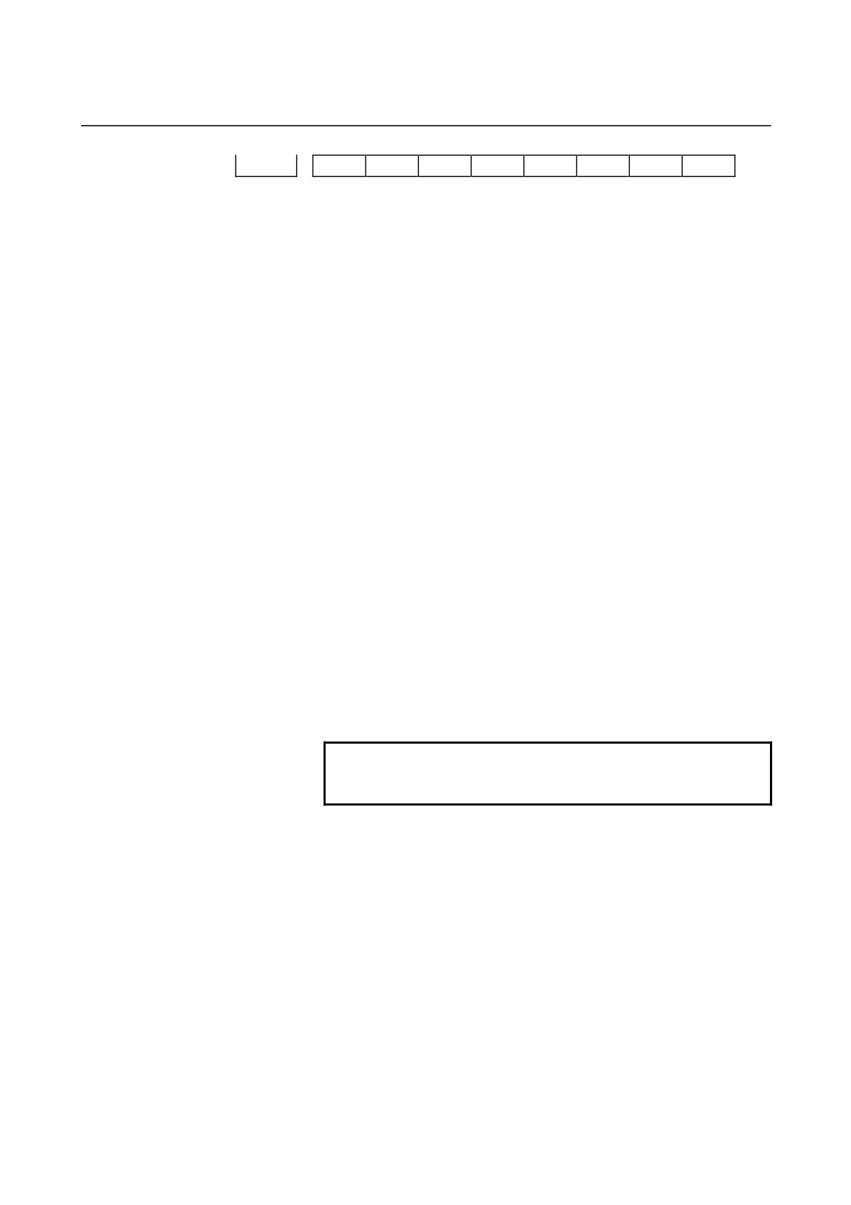
DWL
AUX
[Data type]
Bit
AUX
The least increment of the command of the second miscellaneous
function specified with a decimal point
0 : Assumed to be 0.001
1 : Depending on the input increment. (For input in mm, 0.001 is
assumed, or for input in inches, 0.0001 is assumed.)
DWL
The dwell time (G04) is:
0 : Always dwell per second.
1 : Dwell per second in the feed per minute mode, or dwell per
rotation in the feed per rotation mode.
PPS
The passing-point signal output function is:
0 : Not used
1 : Used
CCR
Addresses used for chamfering and corner rounding
0 : Address used for chamfering and corner rounding is "I" or "K",
not "C". In direct drawing dimension programming, addresses
",C", ",R", and ",A" (with comma) are used in stead of "C", "R",
and "A".
1 : Addresses used for chamfering, corner rounding, and direct
drawing dimension programming are "C", "R", and "A" without
comma. Thus, addresses A and C cannot be used as the names of
axes.
DDP
Angle commands by direct drawing dimension programming
0 : Normal specification
1 : A supplementary angle is given.
QLG
When the passing-point signal output function is used, the remaining
distance to be traveled specified in address ",Q" is:
0 : The combined distance of all axes
1 : The distance of the longest axis
NOTE
This parameter is valid when bit 7 (QAB) of
parameter No.3405 = 0.
QAB
When the passing-point signal output function is used, address ",Q"
specifies:
0 : Remaining distance to be traveled
1 : Coordinate value of the longest axis
- 172 -
B-64120EN/01
4.DESCRIPTION OF PARAMETERS
#7
#6
#5
#4
#3
#2
#1
#0
C07
C05
C04
C03
C02
C01
3406
C07
C05
C04
C03
C02
C01
#7
#6
#5
#4
#3
#2
#1
#0
C14
C11
C10
C08
3407
C15
C14
C13
C11
C10
C09
C08
#7
#6
#5
#4
#3
#2
#1
#0
C16
3408
C20
C19
C18
C17
C16
#7
#6
#5
#4
#3
#2
#1
#0
3409
CFH
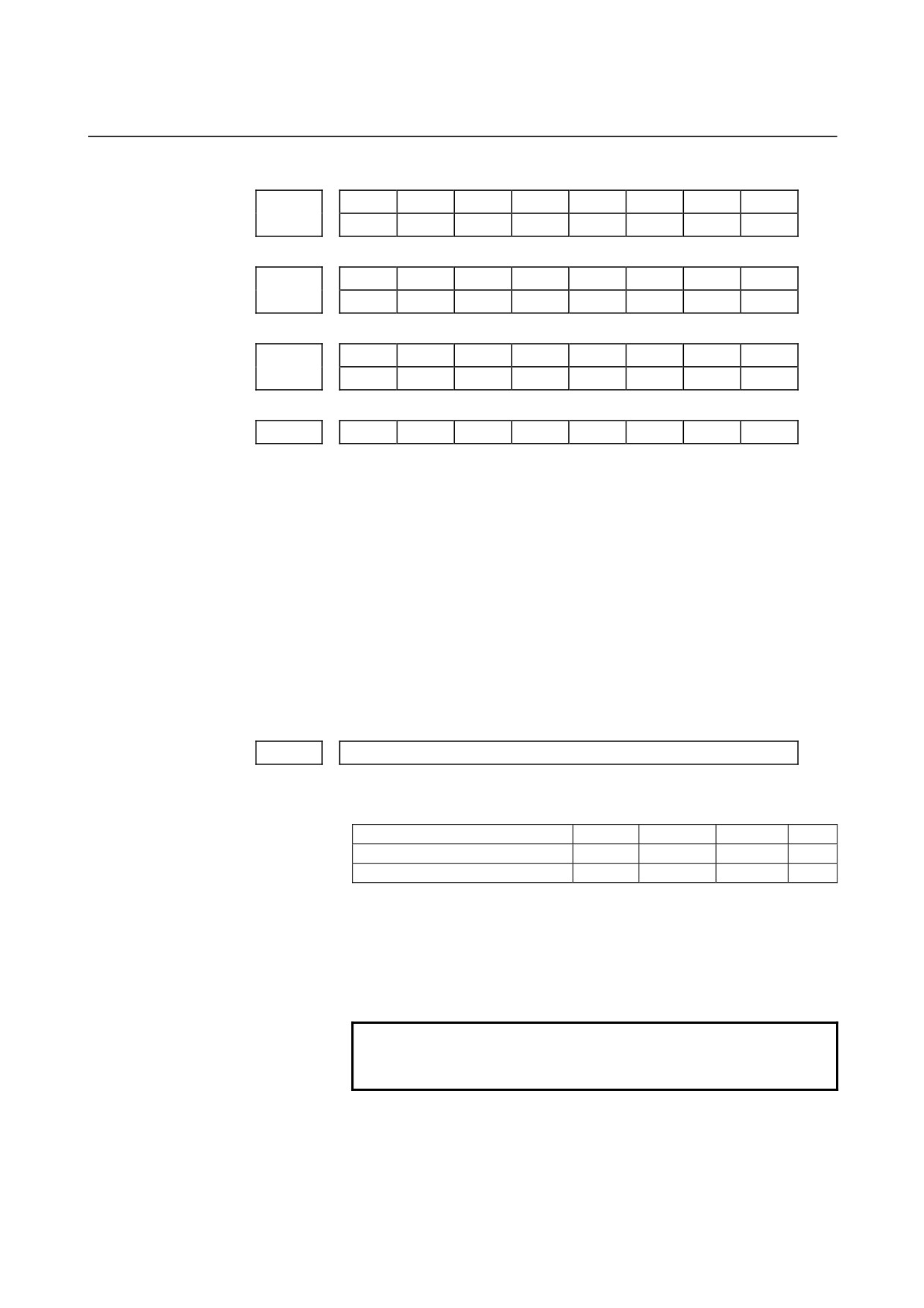
[Data type]
Bit
Cxx (xx: 01 to 20)
When bit 6 (CLR) of parameter No.3402 is 1, the reset button on the
MDI panel, the external reset signal, the reset and rewind signal, or
emergency stop will,
0 : Clear the G code with group number xx.
1 : Not clear the G code with group number xx.
CFH
When bit 6 (CLR) of parameter No.3402 is 1, the reset button on the
MDI panel, the external reset signal, the reset and rewind signal, or
emergency stop will,
0 : Clear F codes, H codes (for the M series), D codes (for the M
series), and T codes (for the T series).
1 : Not clear F codes, H codes (for the M series), D codes (for the M
series), and T codes (for the T series).
3410
Tolerance of arc radius
[Data type]
2-word
[Unit of data]
Input increment
IS-A
IS-B
IS-C
Unit
Millimeter input
0.01
0.001
0.0001
mm
Inch input
0.001
0.0001
0.00001
inch
[Valid data range]
1 to 99999999
When a circular interpolation command (G02, G03) is executed, the
tolerance for the radius between the start point and the end point is set.
If the difference of radii between the start point and the end point
exceeds the tolerance set here, a P/S alarm No.20 is informed.
NOTE
When the set value is 0, the difference of radii is
not checked.
- 173 -
4.DESCRIPTION OF PARAMETERS
B-64120EN/01
3411
M code preventing buffering 1
3412
M code preventing buffering 2
3413
M code preventing buffering 3
:
:
3420
M code preventing buffering 10
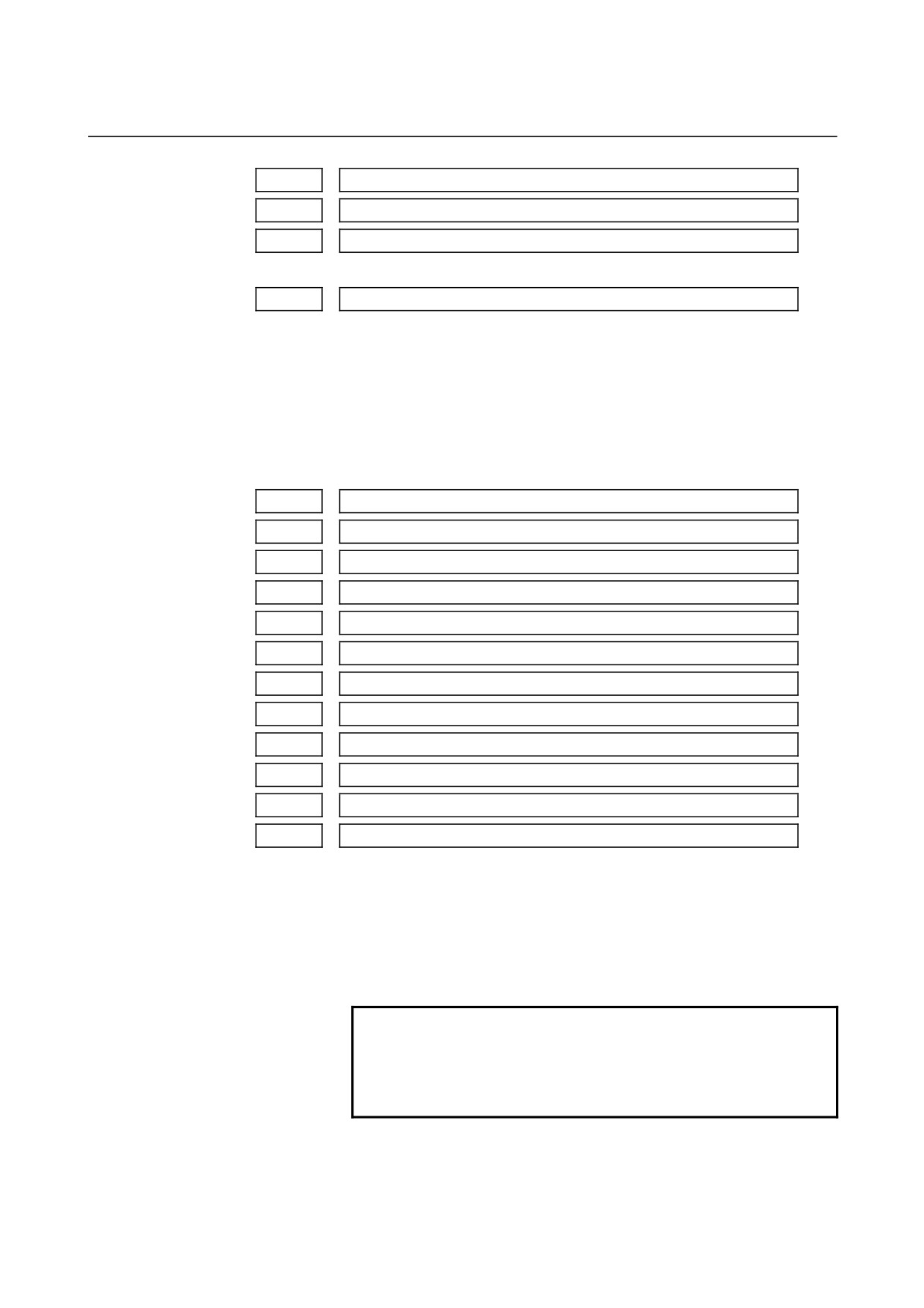
[Data type]
Byte
[Valid data range]
0 to 255
Set M codes that prevent buffering the following blocks. If
processing directed by an M code must be performed by the machine
without buffering the following block, specify the M code.
M00, M01, M02, and M30 always prevent buffering even when they
are not specified in these parameters.
3421
Minimum value 1 of M code preventing buffering
3422
Maximum value 1 of M code preventing buffering
3423
Minimum value 2 of M code preventing buffering
3424
Maximum value 2 of M code preventing buffering
3425
Minimum value 3 of M code preventing buffering
3426
Maximum value 3 of M code preventing buffering
3427
Minimum value 4 of M code preventing buffering
3428
Maximum value 4 of M code preventing buffering
3429
Minimum value 5 of M code preventing buffering
3430
Maximum value 5 of M code preventing buffering
3431
Minimum value 6 of M code preventing buffering
3432
Maximum value 6 of M code preventing buffering
[Data type]
Word
[Valid data range]
0 to 65535
When a specified M code is within the range specified with parameter
Nos. 3421 and 3422, 3423 and 3424, 3425 and 3426, 3427 and 3428,
3429 and 3430, or 3431 and 3432, buffering for the next block is not
performed until the execution of the block is completed.
NOTE
1 The specification of a minimum value that exceeds
the specified maximum value is invalid.
2 When there is only one data item, set the following:
minimum value = maximum value.
- 174 -
B-64120EN/01
4.DESCRIPTION OF PARAMETERS
3435
Central angle limit of circular with R specification
[Data type]
Byte
[Unit of data]
1°
[Valid data range]
0 to 180
Set a central angle limit that can be permitted in commands for
circular interpolation with R specification (G02 and G03). If circular
interpolation of which central angle exceeds the limit is specified, P/S
alarm No.23 is issued.
If this parameter is set to 0, the radius R specification alarm function
is disabled.
#7
#6
#5
#4
#3
#2
#1
#0
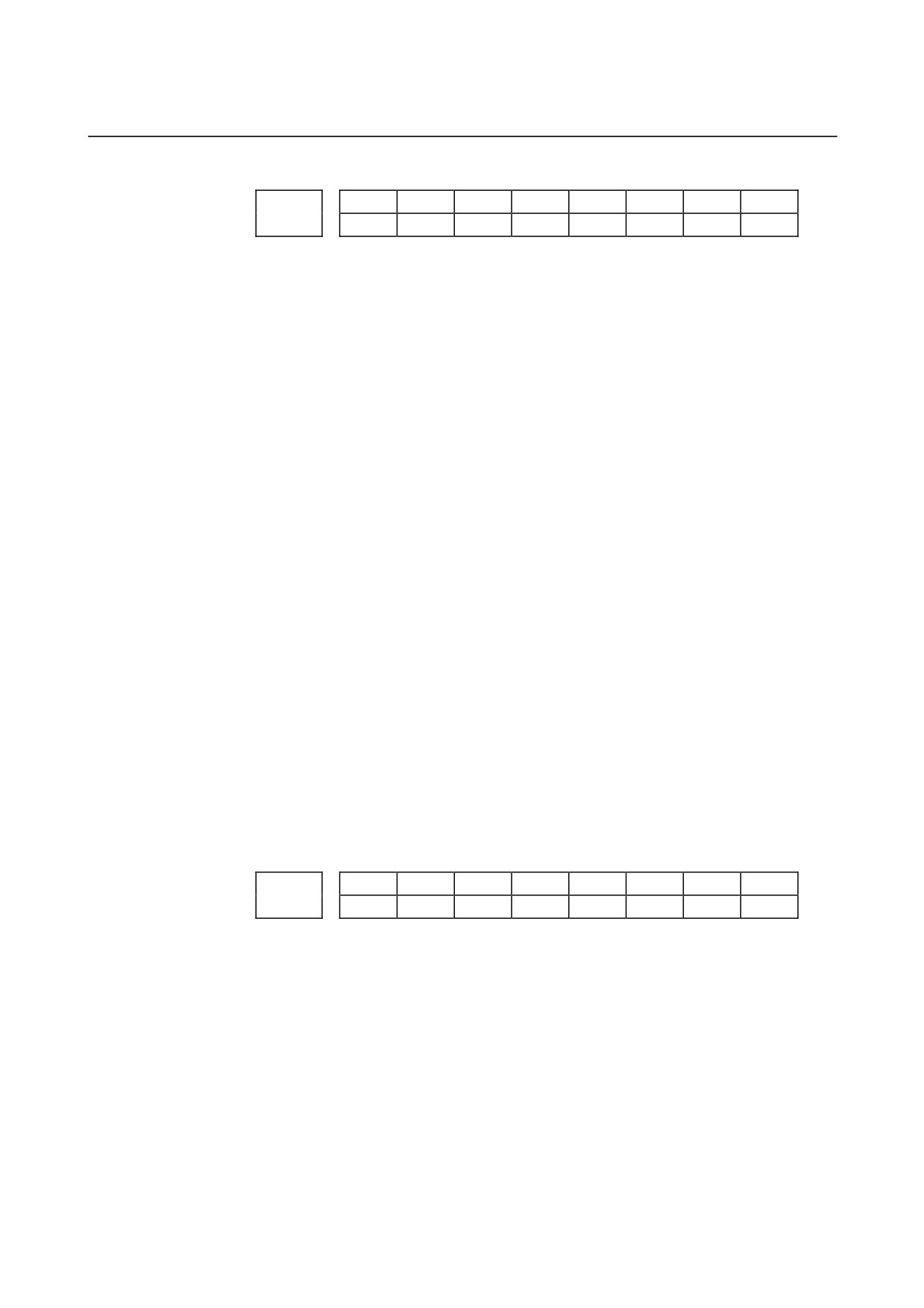
NPS
CQD
3450
BDX
CQD
AUP
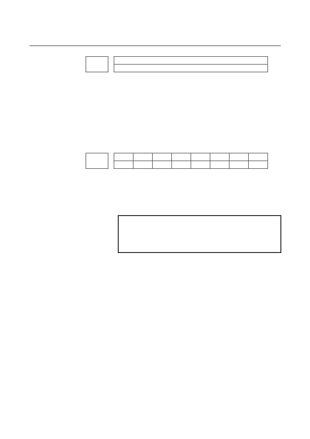
[Data type]
Bit
AUP
When a command for the second miscellaneous function contains a
decimal point or negative sign:
0 : The command is invalid.
1 : The command is valid.
NOTE
For the T series, a decimal point and negative sign
are supported for commands for the second
miscellaneous function, regardless of the setting
made with this parameter.
CQD
The method used for determining the amount of travel in circular
interpolation is:
0 : Series 16 type.
1 : Series 15 type.
NPS
A block that contains M98 Pxxx or M99, and which contains no
addresses other than O and N functions:
0 : As a one-block NC statement involving no movement.
(A single-block stop is caused.)
1 : As a macro statement.
(A single-block stop is not caused. Moreover, the block is not
regarded as a block involving no movement in tool-tip radius
compensation mode.)
BDX
A decimal point specified with address B is handled:
0 : In the conventional way.
1 : In the same way as in a system equipped with the second
auxiliary function.
In a system without second auxiliary function, the decimal point
specified with address B can be handled as in a system equipped with
the second auxiliary function. The following parameters can be used:
•
Bit 0 (AUP) of parameter No. 3450
•
Bit 0 (AUX) of parameter No. 3405
- 175 -
4.DESCRIPTION OF PARAMETERS
B-64120EN/01
#7
#6
#5
#4
#3
#2
#1
#0
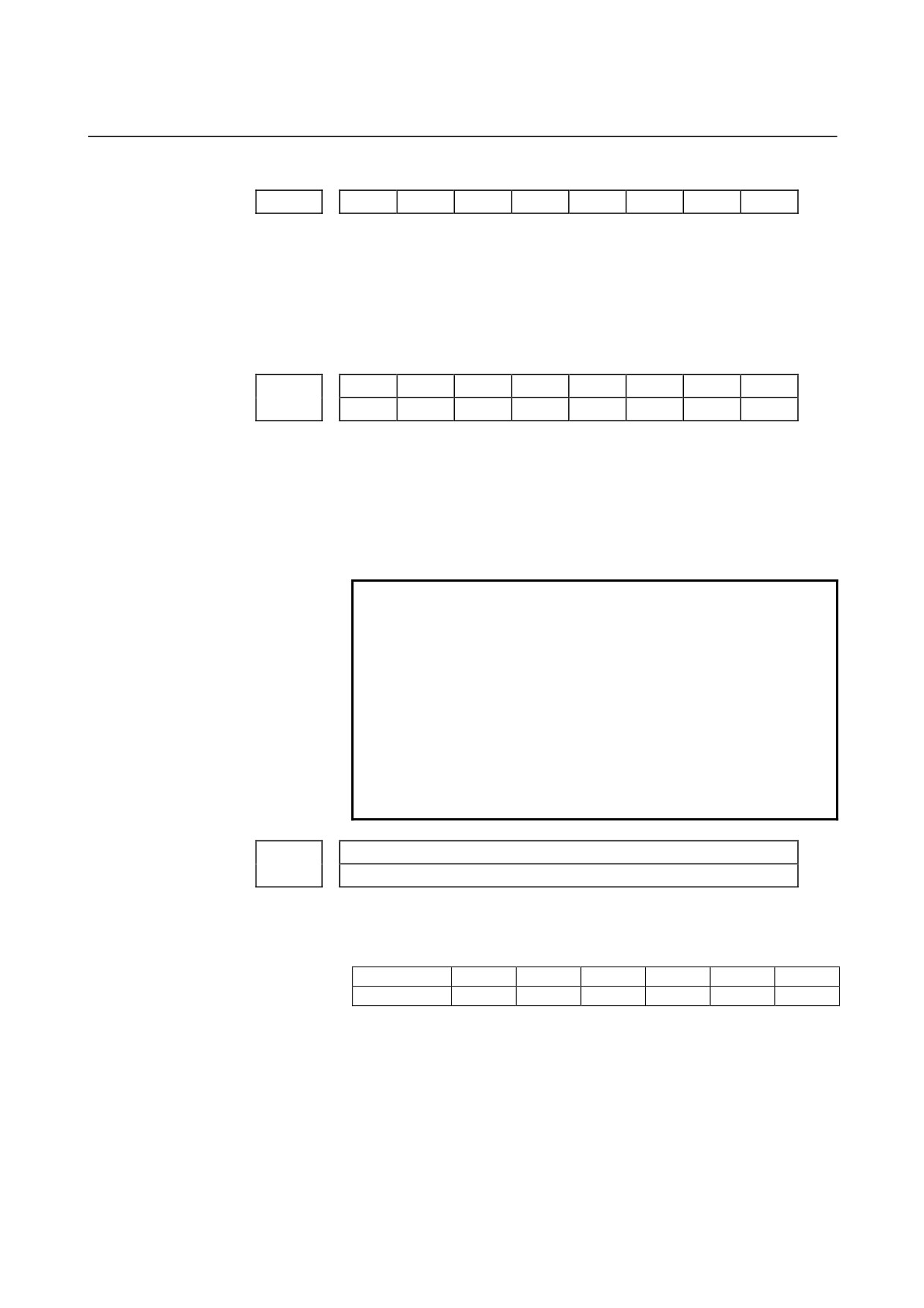
3451
NBN
CCK
SDP
GQS
[Data type]
Bit
GQS
When G33 is specified, the threading start angle shift function (Q) is:
0 : Disabled.
1 : Enabled.
SDP
The function to specify an S command with decimal point is:
0 : Not used.
1 : Used.
An S command with one decimal place can be specified. However, the
S command value is rounded off to the nearest whole number.
Example:
Relationships between specified value and S code output/alarm
S200.5 -> S code output value = 201
S200.2 -> S code output value = 200
S200.12 -> P/S007 alarm is raised.
CCK
If chamfering or corner R is enabled and if the end point specified in
an arc command is not complete,
0 : No alarm is raised.
1 : An alarm (P/S058 alarm) is raised.
This parameter specifies whether an alarm is raised if chamfering or
corner R is enabled, if the end point specified in an arc command is
not complete, and if an address is omitted.
If the end point is omitted in an arc command, chamfering or corner R
may affect the omitted point, and the operation may not be performed
as intended by the programmer. If this parameter is specified, an alarm
can be raised for that type of program execution.
NBN
If bit 0 (NOP) of parameter No. 3404 is set to 1, a block including just
N (sequence number) is:
0 : Ignored.
1 : Not ignored but handled as a single block.
#7
#6
#5
#4
#3
#2
#1
#0
CRD
3453
[Data type]
Bit
CRD
If the functions of chamfering or corner R and direct drawing
dimension programming are both enabled,
0 : Chamfering or corner R is enabled.
1 : Direct drawing dimension programming is enabled.
If the functions of chamfering or corner R and direct drawing
dimension programming are both specified, this parameter specifies
which function is used.
This parameter is displayed also on the setting screen.
("CHAMFERING/DIRECT
DRAWING
DIMENSION
PROGRAMMING") The function to be enabled can be changed
from the setting screen or parameter screen.
- 176 -
B-64120EN/01
4.DESCRIPTION OF PARAMETERS
#7
#6
#5
#4
#3
#2
#1
#0
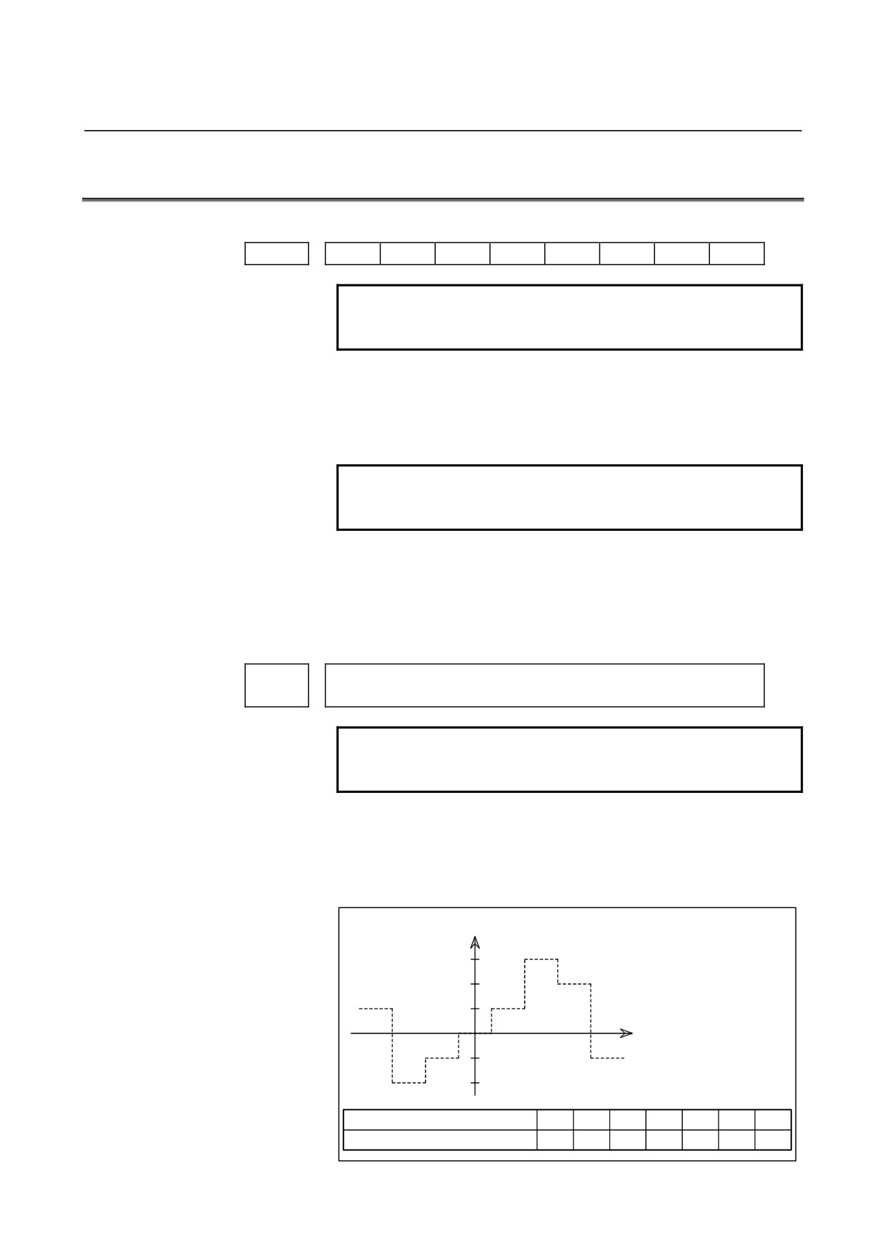
3454
RF2
[Data type]
Bit
RF2
Reference position return commands G28.2 and G30.2, which
suppress in-position checks during reference position return, are:
0 : Invalid.
1 : Valid.
#7
#6
#5
#4
#3
#2
#1
#0
3455
AXDx
[Data type]
Bit axis
AXDx
If a decimal point is omitted for an address with which a decimal point
can be used, the value is determined:
0 : In accordance with the least input increment.
1 : In millimeters, inches, or seconds. (calculator-type decimal point
input)
NOTE
1 This parameter is valid if bit 0 (DPI) of parameter
No. 3401 is set to 0.
2 Because some addresses (such as R and K) are
not related to an axis, setting this parameter for all
axes is not equivalent to setting bit 0 (DPI) of
parameter No. 3401 to 1.
3 This parameter cannot be used together with:
- Macro executor
- Basic operation package
- Macro call argument
3460
Address for second miscellaneous function
[Data type]
Byte
This parameter specifies the address used for the second
miscellaneous function, as follows:
Address
A
B
C
U
V
W
Set value
65
66
67
85
86
87
Address B is assumed when a value other than the above is set.
Axes names cannot be used to specify the address.
- 177 -
4.DESCRIPTION OF PARAMETERS
B-64120EN/01
4.19
PARAMETERS OF PITCH ERROR COMPENSATION
#7
#6
#5
#4
#3
#2
#1
#0
3605
ROPx
BDPx
NOTE
When this parameter has been set, the power must
be turned off before operation is continued.
[Data type]
Bit
BDPx
Both-direction pitch error compensation is:
0 : Not used.
1 : Used.
NOTE
The function of both-direction pitch error
compensation is required.
ROPx
The interval of pitch error compensation for a rotation axis (type A) is:
0 : Restricted by the following equation:
Minimum value = maximum feedrate (rapid traverse rate)/7500.
1 : Not restricted by the following equation:
Minimum value = maximum feedrate (rapid traverse rate)/7500.
Number of the pitch error compensation position for the reference position
3620
for each axis
NOTE
When this parameter is set, the power must be
turned off before operation is continued.
[Data type]
Word axis
[Unit of data]
Number
[Valid data range]
0 to 1023
Set the number of the pitch error compensation position for
the
reference position for each axis.
Pitch error compensation value (absolute value)
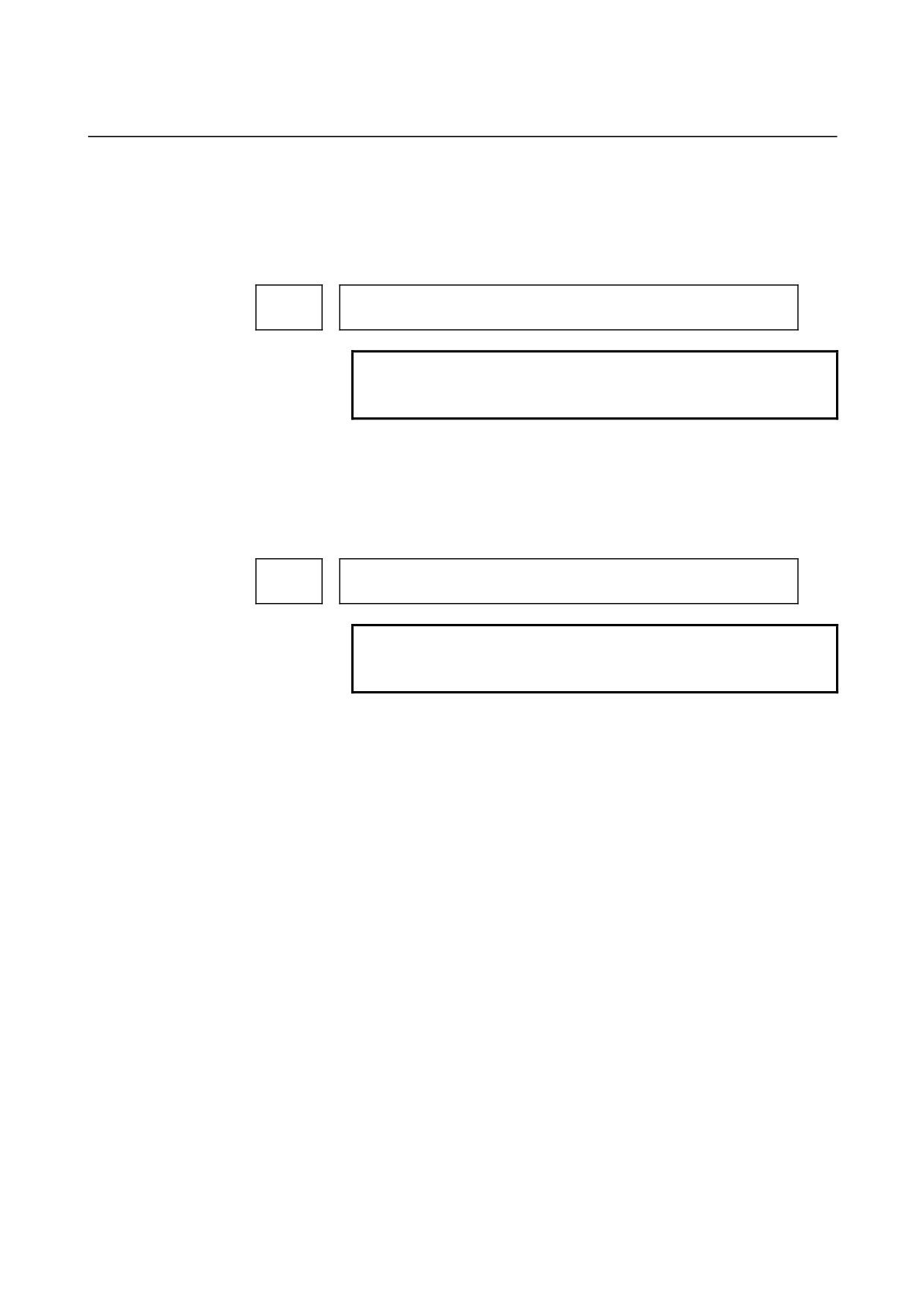
3
2
1
Pitch error compensation
Reference position
position (number)
-1
-2
Compensation position number
31
32
33
34
35
36
37
Set compensating value
-3
+1
+1
+1
+2
-1
-3
- 178 -
B-64120EN/01
4.DESCRIPTION OF PARAMETERS
Fig.4.19 Pitch error compensation position number and value
(example)
In the above example, set
33 as the number of the pitch error
compensation position for the reference position.
Number of the pitch error compensation position at extremely negative
3621
position for each axis
NOTE
When this parameter is set, the power must be
turned off before operation is continued.
[Data type]
Word axis
[Unit of data]
Number
[Valid data range]
0 to 1023
Set the number of the pitch error compensation position
at
the
extremely negative position for each axis.
Number of the pitch error compensation position at extremely positive
3622
position for each axis
NOTE
When this parameter is set, the power must be
turned off before operation is continued.
[Data type]
Word axis
[Unit of data]
Number
[Valid data range]
0 to 1023
Set the number of the pitch error compensation position
at
the
extremely positive position for each axis.
This value must be larger than set value of parameter (No.3620).
- 179 -
4.DESCRIPTION OF PARAMETERS
B-64120EN/01
3623
Magnification for pitch error compensation for each axis
NOTE
When this parameter is set, the power must be
turned off before operation is continued.
[Data type]
Byte axis
[Unit of data]
1
[Valid data range]
0 to 100
Set the magnification for pitch error compensation for each axis.
If the magnification is set to 1, the same unit as the detection unit is
used for the compensation data. If 0 is set, the same magnification
selected by setting 1 is selected.
3624
Interval between pitch error compensation positions for each axis
NOTE
When this parameter is set, the power must be
turned off before operation is continued.
[Data type]
2-word axis
[Unit of data]
Input increment
IS-A
IS-B
IS-C
Unit
Millimeter machine
0.01
0.001
0.0001
mm
Inch machine
0.001
0.0001
0.00001
inch
Rotation axis
0.01
0.001
0.0001
deg
[Valid data range]
0 to 99999999
The pitch error compensation positions are arranged with equal
spacing. The space between two adjacent positions is set for each axis.
The minimum interval between pitch error compensation positions is
limited and obtained from the following equation:
Minimum interval between pitch error compensation positions
=
maximum feedrate (rapid traverse rate)/7500
Units:
Minimum interval between pitch error compensation positions:
mm, inch, deg
Maximum feedrate: mm/min, inch/min, deg/min
Example:
When the maximum feedrate is 15000 mm/min, the minimum
interval between pitch error compensation positions is 2 mm.
If setting a magnification causes the absolute value of the
compensation amount at a compensation position to exceed
100,
enlarge the interval between the compensation positions by using a
multiple calculated as follows:
Multiple = maximum compensation amount (absolute value)/128
(Round the remainder up to the nearest integer.)
Minimum interval between pitch error compensation positions
= Value obtained from the above maximum feedrate × multiple
[Example 1]
For linear axis
•
Machine stroke: -400 mm to + 800 mm
- 180 -
B-64120EN/01
4.DESCRIPTION OF PARAMETERS
•
Interval between the pitch error compensation positions: 50 mm
•
No. of the compensation position of the reference position: 40
If the above is specified, the No. of the farthest compensation point in
the negative direction is as follows:
No. of the compensation position of the reference position -
(Machine stroke length in the negative direction/Interval between the
compensation points) + 1
= 40 - 400/50 + 1
=33
No. of the farthest compensation position in the positive direction is as
follows:
No. of the compensation position of the reference position +
(Machine stroke length in the positive direction/Interval between the
compensation positions)
= 40 + 800/50
= 56
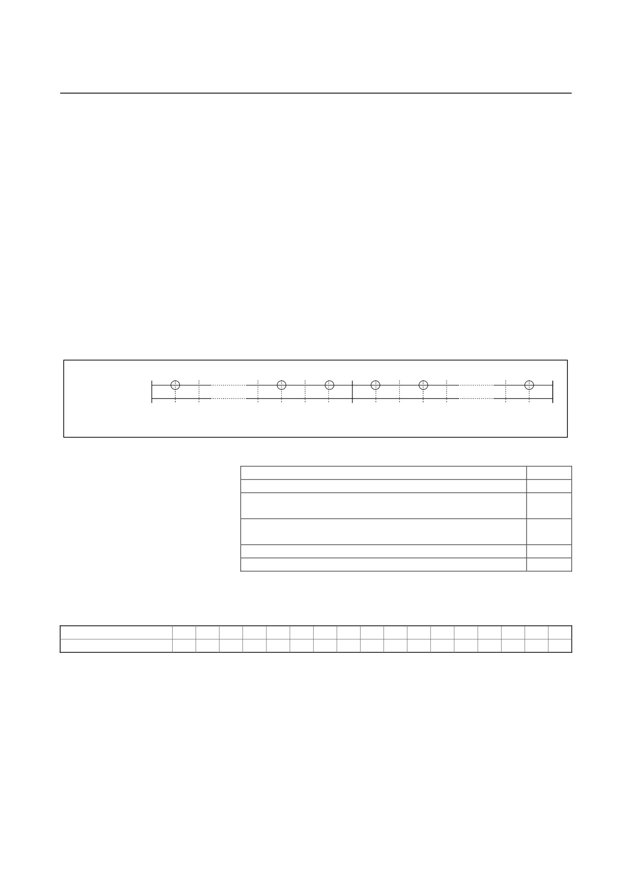
The correspondence between the machine coordinate and the
compensation position No. is as follows:
-400
-350
-100
-50
0
50
100
750
800
Machine
coordinate (mm)
Compensation point
No.
33
39
40
41
42
56
Compensation values are output at the positions indicated by f.
Therefore, set the parameters as follows:
Parameter
Setting
No. 3620: Compensation point number for reference position
40
No. 3621: Compensation point number for farthest point in the
33
negative direction
No. 3622: Compensation point number for farthest point in the
56
positive direction
No. 3623: Compensation magnification
1
No. 3624: Compensation point interval
50000
The compensation value is output at the compensation position No.
corresponding to each section between the coordinates.
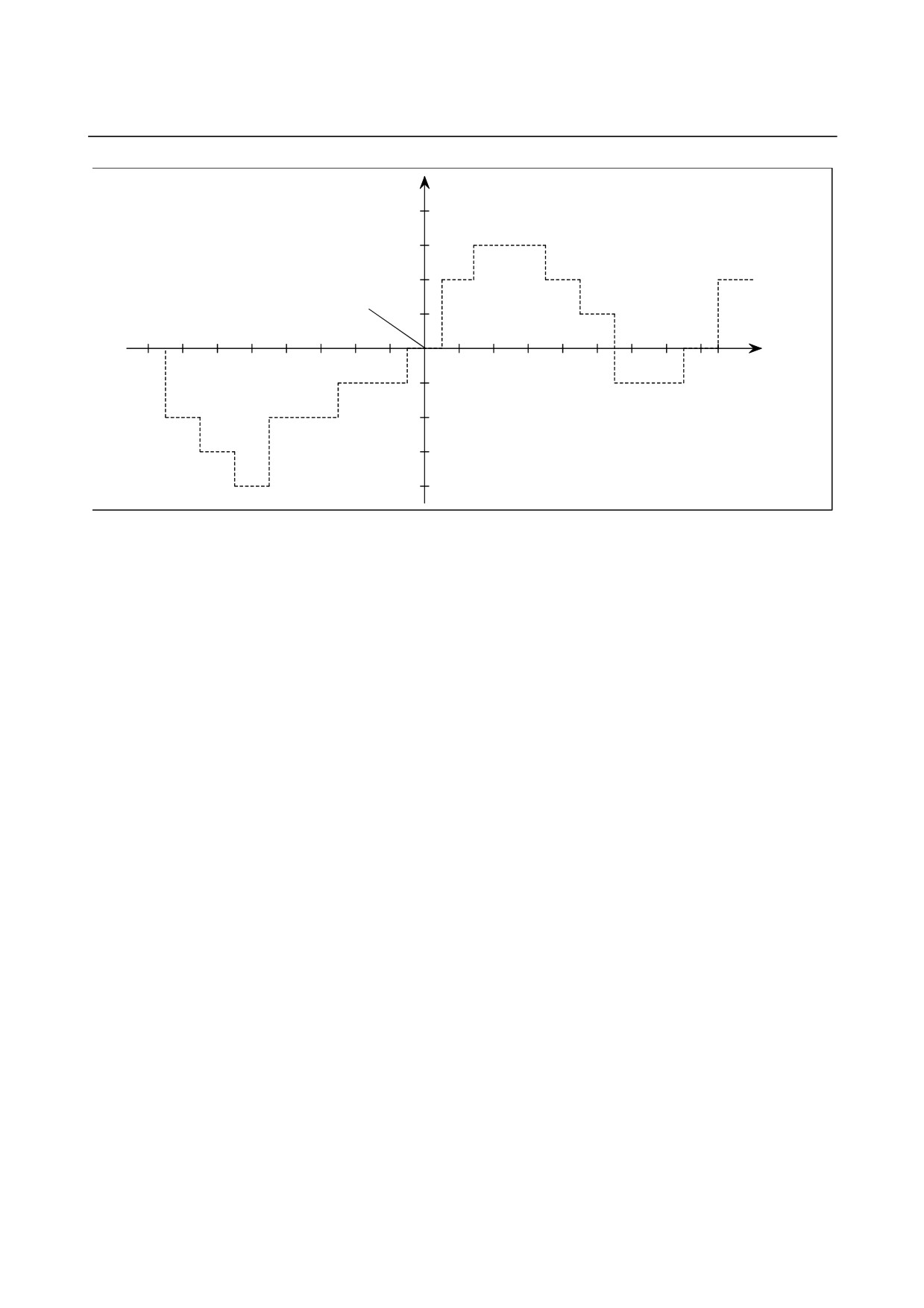
The following is an example of the compensation values.
No.
33
34
35
36
37
38
39
40
41
42
43
44
45
46
47
48
49
Compensation values
+2
+1
+1
-2
0
-1
0
-1
+2
+1
0
-1
-1
-2
0
+1
+2
- 181 -
4.DESCRIPTION OF PARAMETERS
B-64120EN/01
Pitch error compensation amount (absolute value)
+4
+3
+2
Reference position
+1
0
-400
-300
-200
-100
100
200
300
400
(mm)
-1
-2
-3
-4
[Example 2]
For the rotation axis
•
Amount of movement per rotation: 360°
•
Interval between pitch error compensation position: 45°
•
No. of the compensation position of the reference position: 60
If the above is specified, the No. of the farthest compensation position
in the negative direction for the rotation axis is always equal to the
compensation position No. of the reference position.
The No. of the farthest compensation position in the positive direction
is as follows:
No. of the compensation position of the reference position +
(Move amount per rotation/Interval between the compensation
position)
= 60 + 360/45
= 68
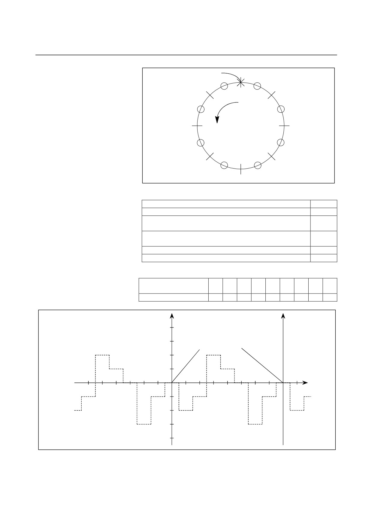
The correspondence between the machine coordinate and the
compensation position No. is as follows:
The compensation value is output at the circled position.
If the sum of the compensation value from 61 to 68 is not zero, the
pitch error per rotation accumulates, resulting in a positional shift.
For compensation position 60, set the same compensation value as for
68.
- 182 -
B-64120EN/01
4.DESCRIPTION OF PARAMETERS
Reference position
0.0
45.0
315.0
(61)
(68)
(60)
(62)
(67)
90.0
270.0
(+)
(63)
(66)
(64)
(65)
135.0
225.0
180.0
Set the parameters as follows:
Parameter
Setting
No. 3620: Compensation point number for reference position
60
No. 3621: Compensation point number for farthest point in the
60
negative direction
No. 3622: Compensation point number for farthest point in the
68
positive direction
No. 3623: Compensation magnification
1
No. 3624: Compensation point interval
45000
The following is an example of compensation values.
No. of the
60
61
62
63
64
65
66
67
68
compensation position
Compensation value
+1
-2
+1
+3
-1
-1
-3
+2
+1
Pitch error compensation value
(absolute value)
+4
+3
Reference position
+2
+1
Machine coordinate
0
0
90
135
180
225
270
315
45
90
135
180
225
270
315
45
(deg)
-1
-2
-3
-4
- 183 -
4.DESCRIPTION OF PARAMETERS
B-64120EN/01
Travel distance per revolution in pitch error compensation of rotation axis
3625
type
NOTE
When this parameter has been set, the power must
be turned off before operation is continued.
[Data type]
2-word axis
[Valid data range]
0 to 99999999
If the pitch error compensation of rotation axis type is performed (bit
1 (ROSx) of parameter No. 1006 is set to 0 and bit 0 (ROTx) of
parameter No. 1006 is set to 1), set the travel distance per revolution.
The travel distance per revolution does not have to be 360 degrees,
and a cycle of pitch error compensation of rotation axis type can be
set.
However, the travel distance per revolution, compensation interval,
and number of compensation points must satisfy the following
condition:
(Travel distance per revolution) = (Compensation interval) × (Number
of compensation points)
The compensation at each compensation point must be set so
that the total compensation per revolution equals 0.
NOTE
1 If 0 is set, the travel distance per revolution
becomes 360 degrees.
2 When setting a value other than 360 (and 0)
degrees, set the same value as the value set in
parameter No. 1260.
Number of pitch error compensation point at the farthest end in the negative
3626
direction (for movement in the negative direction)
NOTE
When this parameter has been set, the power must
be turned off before operation is continued.
[Data type] Word axis
[Unit of data] Number
[Valid data range]
0 to 1023, 3000 to 4023
When using both-direction pitch error compensation, set the number
of pitch error compensation point at the farthest end in the negative
direction for a movement in the negative direction.
NOTE
1 For a movement in the positive direction, set the
compensation point number at the farthest end in
the negative direction in parameter No. 3621.
2 A set of compensation data items for a single axis
should not be set to lie astride 1023 and 3000.
- 184 -

B-64120EN/01
4.DESCRIPTION OF PARAMETERS
Pitch error compensation (absolute value) at reference position when a
3627
movement to the reference position is made from the direction opposite to
the direction of reference position return
NOTE
When this parameter has been set, the power must
be turned off before operation is continued.
[Data type] Word axis
[Unit of data] Detection unit
[Valid data range]
-32768 to 32767
Set the absolute value of pitch error compensation at reference
position when a movement to the reference position is made from the
negative direction if the direction of reference position return (bit 5
(ZMI) of parameter No.
1006) is positive or from the positive
direction if the direction of reference position return is negative.
- 185 -
4.DESCRIPTION OF PARAMETERS
B-64120EN/01
4.20
PARAMETERS OF SPINDLE CONTROL
#7
#6
#5
#4
#3
#2
#1
#0
3700
ESP
ESV
MSE
NRF
[Data type]
Bit
NRF
The first move command (such as G00 and G01) after the serial
spindle is switched to Cs axis contouring control performs:
0 : Positioning after returning to the reference position.
1 : Normal positioning.
NOTE
When using the Cs axis establishment function,
this parameter is recommended to be set to 1.
MSE
Rigid tapping synchronization error data output when bit 5 (ESV) of
parameter No. 3700 is set to 1 or when bit 7 (ESP) of parameter No.
3700 is set to 1 is:
0 : A synchronization error in the positional deviation.
(equivalent
to DGN No. 456)
1 : A synchronization error in the machine position.
(equivalent to
DGN No. 459)
ESV
When bit 7 (ESP) of parameter No. 3700 is set to 1, rigid tapping
synchronization error data is:
0 : Not output to the servo system.
1 : Output to the servo system.
NOTE
Set this parameter as necessary when making
servo and spindle adjustments by using a servo
guide and so forth. After completing adjustments,
reset this parameter to 0.
ESP
Rigid tapping synchronization error data is:
0 : Not output to the spindle.
1 : Output to the spindle.
NOTE
Set this parameter as necessary when making
servo and spindle adjustments by using a servo
guide and so forth. After completing adjustments,
reset this parameter to 0.
- 186 -

B-64120EN/01
4.DESCRIPTION OF PARAMETERS
#7
#6
#5
#4
#3
#2
#1
#0
3701
SS2
ISI
NOTE
When this parameter is set, the power must be
turned off before operation is continued.
[Data type]
Bit
ISI
The serial interface for the first and second spindles are:
0 : Used.
1 : Not used.
NOTE
1 This parameter is valid when the spindle serial
output option is provided.
2 It is used when the CNC is started with serial
interface control for the first and second serial
spindles disabled temporarily (for example, for
CNC startup adjustment).
3 Usually, it should be set to 0.
4 If this parameter is set to 1 when using the serial
spindle and analog spindle at the same time, the
analog spindle is set the first axis.
SS2
In serial spindle control, the second spindle is:
0 : Not used.
1 : Used.
NOTE
1 This parameter is valid, when the spindle serial
output option is provided and parameter ISI(bit 1 of
parameter No.3701)is 0.
2
(a) Confirmation of connection of the second serial
spindle amplifier, and communication with it
(b) Control of the second spindle during
asynchronous control (SIND2)
When this parameter is set, it is also necessary to
set the serial spindle parameter for the second
spindle.
- 187 -
4.DESCRIPTION OF PARAMETERS
B-64120EN/01
#7
#6
#5
#4
#3
#2
#1
#0
3702
OR2
OR1
NOTE
When this parameter is set, the power must be
turned off before operation is continued.
[Data type]
Bit
OR1
Whether the stop-position external-setting type orientation function is
used by the first spindle motor
0 : Not used
1 : Used
OR2
Whether the stop-position external-setting type orientation function is
used by the second spindle motor
0 : Not used
1 : Used
#7
#6
#5
#4
#3
#2
#1
#0
MPP
3703
NOTE
When this parameter is set, the power must be
turned off before operation is continued.
[Data type]
Bit
MPP
Under multi-spindle control, the spindle is not selected by a spindle
signal
(SWS1 to SWS3 <G027 bits 0 to 2>), and a programmed
command (address P) is:
0 : Not used.
1 : Used.
NOTE
If this parameter is set to 1, set parameters No.
3781 to No. 3783 as well.
- 188 -
B-64120EN/01
4.DESCRIPTION OF PARAMETERS
#7
#6
#5
#4
#3
#2
#1
#0
3704
CSS
SSS
NOTE
When this parameter has been set, the power must
be turned off before operation is continued.
[Data type]
Bit
SSS
Synchronous spindle control by each spindle is:
0 : Not performed.
1 : Performed.
The master axis and slave axis of synchronous spindle control can be
selected from the first to second spindles.
The target spindle of synchronous spindle control is specified
in
parameters No. 4831 to 4832.
In addition, the following signals affect the control.
Synchronous spindle signal of each spindle
SPSYC1 to SPSYC2 <G288 bits 0 to 1>
Signal of synchronous control of the spindle phase for each spindle
SPPHS1 to SPPHS2 <G289 bits 0 to 1>
CSS
On the second spindle, Cs contour control is:
0 : Not performed.
1 : Performed.
If Cs contour control is performed on each spindle as specified
by this parameter, set parameter No. 1023 as indicated below.
Setting
-1 = Axis of Cs contour control by the first spindle
-2 = Axis of Cs contour control by the second spindle
NOTE
1 A single spindle cannot be specified as multiple
axes of Cs contour control.
2 This parameter cannot be used with the spindle
positioning function. When using the spindle
positioning function, set bit 7 (CSS) of parameter
No. 3704 to 0.
#7
#6
#5
#4
#3
#2
#1
#0
EVS
ESF
3705
SFA
NSF
SGT
SGB
GST
ESF
[Data type]
Bit
ESF
When the spindle control function (Spindle analog output or Spindle
serial output) is used, and the constant surface speed control function
is used or bit 4 (GTT) of parameter No.3705 is set to 1:
0 : S codes and SF are output for all S commands.
1 : S codes and SF are not output for an S command in constant
surface speed control mode (G96 mode) or for an S command
used to specify maximum spindle speed clamping (G50S---;)
- 189 -

4.DESCRIPTION OF PARAMETERS
B-64120EN/01
NOTE
For the T series, this parameter is enabled when bit
4 (EVS) of parameter No.3705 is set to 1.
For the M series, SF is not output:
(1) For an S command used to specify maximum
spindle speed clamping (G92S---;) in constant
surface speed control mode
(2) When bit 5 (NSF) of parameter No.3705 is set
to 1
GST
The SOR signal is used for:
0 : Spindle orientation
1 : Gear shift
NOTE
If the function of constant surface speed control or
bit 4 (GTT) of parameter No. 3706 is specified, this
parameter is invalid.
SGB
Gear switching method
0 : Method A (Parameters 3741 to 3743 for the maximum spindle
speed at each gear are used for gear selection.)
1 : Method B (Parameters 3751 and 3752 for the spindle speed at the
gear switching point are used for gear selection.)
SGT
Gear switching method during tapping cycle (G84 and G74)
0 : Method A (Same as the normal gear switching method)
1 : Method B (Gears are switched during tapping cycle according to
the spindle speed set in parameters 3761 and 3762).
EVS
When the spindle control function (Spindle analog output or Spindle
serial output) is used, S codes and SF are:
0 : Not output for an S command.
1 : Output for an S command.
NOTE
The output of S codes and SF for an S command in
constant surface speed control mode (G96), or for
an S command used to specify maximum spindle
speed clamping (G50S---;) depends on the setting
of bit 0 (ESF) of parameter No.3705.
NSF
If the function of constant surface speed control is specified or if bit 4
(GTT) of parameter No. 3706 is set to 1 and when an S code is
specified,
0 : SF is output.
1 : SF is not output.
SFA
The SF signal is output:
0 : When gears are switched.
1 : Irrespective of whether gears are switched.
- 190 -
B-64120EN/01
4.DESCRIPTION OF PARAMETERS
#7
#6
#5
#4
#3
#2
#1
#0
TCW
CWM
ORM
PG2
PG1
3706
TCW
CWM
ORM
GTT
PG2
PG1
[Data type]
Bit
PG2 and PG1
Gear ratio of spindle to position coder
Magnification
PG2
PG1
×1
0
0
Number of spindle
×2
0
1
revolutions
Magnification=
×4
1
0
Number of position
×8
1
1
coder revolutions
GTT
Selection of a spindle gear selection method
0: Type M.
1 : Type T.
NOTE
1
The gear selection method differs as described
below. For details, refer to the description of
spindle control in the connection manual (function
part).
Type M:
The CNC determines a proper gear from the
parameter setting and S command value, and
requests the PMC to specify the gear and its
switching.
In addition, spindle control is exercised according
to a gear selected by the CNC.
Type T:
The CNC exercises spindle control according to a
gear selected by the PMC.
2
When the constant surface speed control option is
selected, type T is selected, regardless of whether
this parameter is specified.
3
When type T spindle gear switching is selected, the
following parameters have no effect:
No.3705#2 SGB, No.3751, No.3752, No.3705#3
SGT,
No.3761, No.3762, No.3705#6 SFA, No.3735,
No.3736
On the other hand, parameter No. 3744 becomes
usable for ordinary spindle control.
ORM
Voltage polarity during spindle orientation
0 : Positive
1 : Negative
TCW, CWM
Voltage polarity when the spindle speed voltage is output
TCW
CWM
Voltage polarity
0
0
Both M03 and M04 positive
0
1
Both M03 and M04 negative
- 191 -
4.DESCRIPTION OF PARAMETERS
B-64120EN/01
1
0
M03 positive, M04 negative
1
1
M03 negative, M04 positive
#7
#6
#5
#4
#3
#2
#1
#0
3707
P22
P21
[Data type]
Bit
P22 and P21
Gear ratio of spindle to second position coder
Magnification
P22
P21
×1
0
0
Number of spindle
×2
0
1
revolutions
Magnification=
×4
1
0
Number of position
×8
1
1
coder revolutions
NOTE
This parameter is valid when the multi-spindle
control option is selected.
#7
#6
#5
#4
#3
#2
#1
#0
TSO
SOC
SVD
SAT
SAR
3708
TSO
SOC
SVD
SAR
[Data type]
Bit
SAR
The spindle speed arrival signal is:
0 : Not checked
1 : Checked
SAT
Check of the spindle speed arrival signal at the start of executing the
thread cutting block
0 : The signal is checked only when SAR, #0 of parameter 3708, is
set.
1 : The signal is always checked irrespective of whether SAR is set.
NOTE
When thread cutting blocks are consecutive, the
spindle speed arrival signal is not checked for the
second and subsequent thread cutting blocks.
SVD
When the SIND signal is on, the detection of spindle speed fluctuation
is:
0 : Disabled
1 : Enabled
SOC
During constant surface speed control (G96 mode), the speed clamp
by the maximum spindle speed clamp command (M series: G92 S_; T
series: G50 S_;) is carried out:
0 : Before spindle speed override.
1 : After spindle speed override.
If this parameter is set to
0, the spindle speed may exceed the
maximum spindle speed (numeric value following S in G92 S_; (M
series) or G50 S_; (T series)).
If this parameter is set to
1, the spindle speed is limited to the
maximum spindle speed.
- 192 -
B-64120EN/01
4.DESCRIPTION OF PARAMETERS
The spindle speed is limited to the upper limit of spindle speed
specified in parameter No. 3772, irrespective of the setting of this
parameter.
TSO
During a threading or tapping cycle, the spindle override is:
0 : Disabled (tied to 100%).
1 : Enabled.
NOTE
During rigid tapping, the override is tied to 100%,
irrespective of the setting of this parameter.
#7
#6
#5
#4
#3
#2
#1
#0
THB
MRS
MSI
RSC
SAM
3709
SMC
RSC
[Data type]
Bit
SAM
The sampling frequency to obtain the average spindle speed
0 :
4 (Normally, set to 0.)
1 :
1
RSC
In the constant surface speed control mode, the surface speed of a
rapid traverse block is calculated:
0 : In accordance with the coordinates of the end point.
1 : In accordance with the current value, as in cutting feed.
MSI
In multi-spindle control, the SIND signal is valid
0 : Only when the first spindle is valid (SIND signal for the 2nd, 3rd
spindle becomes ineffective)
1 : For each spindle irrespective of whether the spindle is selected
(Each spindle has its own SIND signal).
MRS
When the S 12-bit code signals and actual spindle speed signals are
output in multi-spindle control:
0: Signals common to the first through second spindles are used.
In this case, information about a spindle selected by the spindle
selection signal (SWS1-SWS2<G027#0-#1>) is output.
1: Information about each of the first through third spindles is
output on individual signals.
When MRS
Signal
When MRS is set to 0
is set to 1
S 12-bit code signals
First spindle (SWS1 = 1)
R01O-R12O<F036,F037>
Second spindle (SWS1 =
First spindle
Actual spindle speed signals
0, SWS2 = 1)
AR0-AR15<F040,F041>
S 12-bit code signals 2
R01O3-R12O2<F200,F201>
Second
-
Actual spindle speed signals 2
spindle
AR200-AR215<F202,F203>
NOTE
To use this parameter, the multi-spindle control
option and spindle serial output are required.
SMC
The function to check a large S command is:
- 193 -
4.DESCRIPTION OF PARAMETERS
B-64120EN/01
0 : Not used.
1 : Used.
If a spindle gear of M type is selected, this function compares the
specified S value and the settings of parameters No. 3741 to No. 3743
and raises an alarm if the S value is greater.
If this function is used, specifying an S value larger than the settings
of parameters No. 3741 to No. 3743 causes P/S alarm 5310 to be
raised.
NOTE
This function cannot be used together with any of
bit 4 (GTT) of parameter No. 3706, constant
surface speed control, or multi-spindle control.
THB
The threading start type is:
0 : Type A.
1 : Type B.
NOTE
When using PMC axis control, set this parameter to
1.
#7
#6
#5
#4
#3
#2
#1
#0
CSL
3710
CSL
SGR
[Data type]
Bit
SGR
When method B is selected as the spindle gear switching method for a
tapping cycle (G84 or G74) (bit 3 (SGT) of parameter No. 3705 = 1),
gear switching method B is used for:
0 : Both tapping and rigid tapping.
1 : Rigid tapping only.
CSL
In Cs contour control mode, fine acceleration/deceleration is disabled
for:
0 : An axis selected by the signal (CDFn <G0127>) issued from the
PMC. (n = 1 to 4)
1 : An axis for which interpolation is performed with the Cs contour
controlled axis (parameter No. 39n0). (n = 0 to 2)
#7
#6
#5
#4
#3
#2
#1
#0
3712
CSF
[Data type]
Bit
CSF
The Cs axis coordinate setup function is:
0 : Disabled.
1 : Enabled.
NOTE
When setting this parameter to 1, also set bit 5 of
parameter No. 4353 to 1.
- 194 -
B-64120EN/01
4.DESCRIPTION OF PARAMETERS
#7
#6
#5
#4
#3
#2
#1
#0
SIM
3713
NOTE
When this parameter has been set, the power must
be turned off before operation is continued.
[Data type]
Bit
SIM
In multi-spindle control, when address P is used for spindle selection
(bit 3 of parameter No. 3703 = 1), and an axis move command and S
command are specified in the same block:
0 : The S command becomes valid after an axis movement is
completed.
1 : The S command becomes valid at the same time when an axis
movement is made.
#7
#6
#5
#4
#3
#2
#1
#0
3715
NSAx
[Data type]
Bit axis
NSAx
This parameter specifies an axis for which confirmation of the spindle
speed reached signal (SAR) is unnecessary when a move command is
executed for the axis. When a move command is issued only for an
axis for which 1 is set in this parameter, the spindle speed reached
signal (SAR) is not checked.
0 : Confirmation of SAR is necessary.
1 : Confirmation of SAR is unnecessary.
3730
Data used for adjusting the gain of the analog output of spindle speed
[Data type]
Word
[Unit of data]
0.1 %
[Valid data range]
700 to 1250
Set data used for adjusting the gain of the analog output of
spindle speed.
[Adjustment method]
(1) Assign standard value 1000 to the parameter.
(2) Specify the spindle speed so that the analog output of the spindle
speed is the maximum voltage (10 V).
(3) Measure the output voltage.
(4) Assign the value obtained by the following equation to parameter
No.3730.
10 (V)
Set value=
×1000
Measured data (V)
(5) After setting the parameter, specify the spindle speed so that the
analog output of the spindle speed is the maximum voltage.
Confirm that the output voltage is 10V.
- 195 -

4.DESCRIPTION OF PARAMETERS
B-64120EN/01
NOTE
This parameter needs not to be set for serial
spindles.
Compensation value for the offset voltage of the analog output of the spindle
3731
speed
[Data type]
Word
[Unit of data]
Velo
[Valid data range]
-1024 to+1024
Set compensation value for the offset voltage of the analog output of
the spindle speed.
-8191 × Offset voltage (V)
Set value=
12.5
[Adjustment method]
(1) Assign standard value 0 to the parameter.
(2) Specify the spindle speed so that the analog output of the spindle
speed is 0.
(3) Measure the output voltage.
(4) Assign the value obtained by the following equation to parameter
No.3731.
-8191 × Offset voltage (V)
Set value=
12.5
(5) After setting the parameter, specify the spindle speed so that the
analog output of the spindle speed is 0. Confirm that the output
voltage is 0V.
NOTE
This parameter usually need not to be set for serial
spindles (Set to 0).
- 196 -
B-64120EN/01
4.DESCRIPTION OF PARAMETERS
The spindle speed during spindle orientation or the spindle motor speed
3732
during spindle gear shift
[Data type]
Word
[Valid data range]
0 to 20000
Set the spindle speed during spindle orientation or the spindle motor
speed during gear shift.
When GST, #1 of parameter 3705, is set to 0, set the spindle speed
during spindle orientation in rpm.
When GST, #1 of parameter 3705, is set to 1, set the spindle motor
speed during spindle gear shift calculated from the following formula.
For a serial spindle
Spindle motor speed during spindle gear shift
Set value=
×16383
Maximum spindle motor speed
For an analog spindle
Spindle motor speed during spindle gear shift
Set value=
×4095
Maximum spindle motor speed
3735
Minimum clamp speed of the spindle motor
[Data type]
Word
[Valid data range]
0 to 4095
Set the minimum clamp speed of the spindle motor.
Minimum clamp speed of the spindle motor
Set value=
×4095
Maximum spindle motor speed
NOTE
If the function of constant surface speed control or
bit 4 (GTT) of parameter No. 3706 is specified, this
parameter is invalid.
- 197 -
4.DESCRIPTION OF PARAMETERS
B-64120EN/01
3736
Maximum clamp speed of the spindle motor
[Data type]
Word
[Valid data range]
0 to 4095
Set the maximum clamp speed of the spindle motor.
Maximum clamp speed of the spindle motor
Set value=
×4095
Maximum spindle motor speed
NOTE
If the function of constant surface speed control or
bit 4 (GTT) of parameter No. 3706 is specified, this
parameter is invalid.
In this case, the maximum clamp speed of spindle
motor cannot be specified. However, the maximum
spindle speed can be specified by the following
parameters.
Parameter No.3772 (for the first axis)
Parameter No.3802 (for the second axis)
Parameter No.3882 (for the third axis)
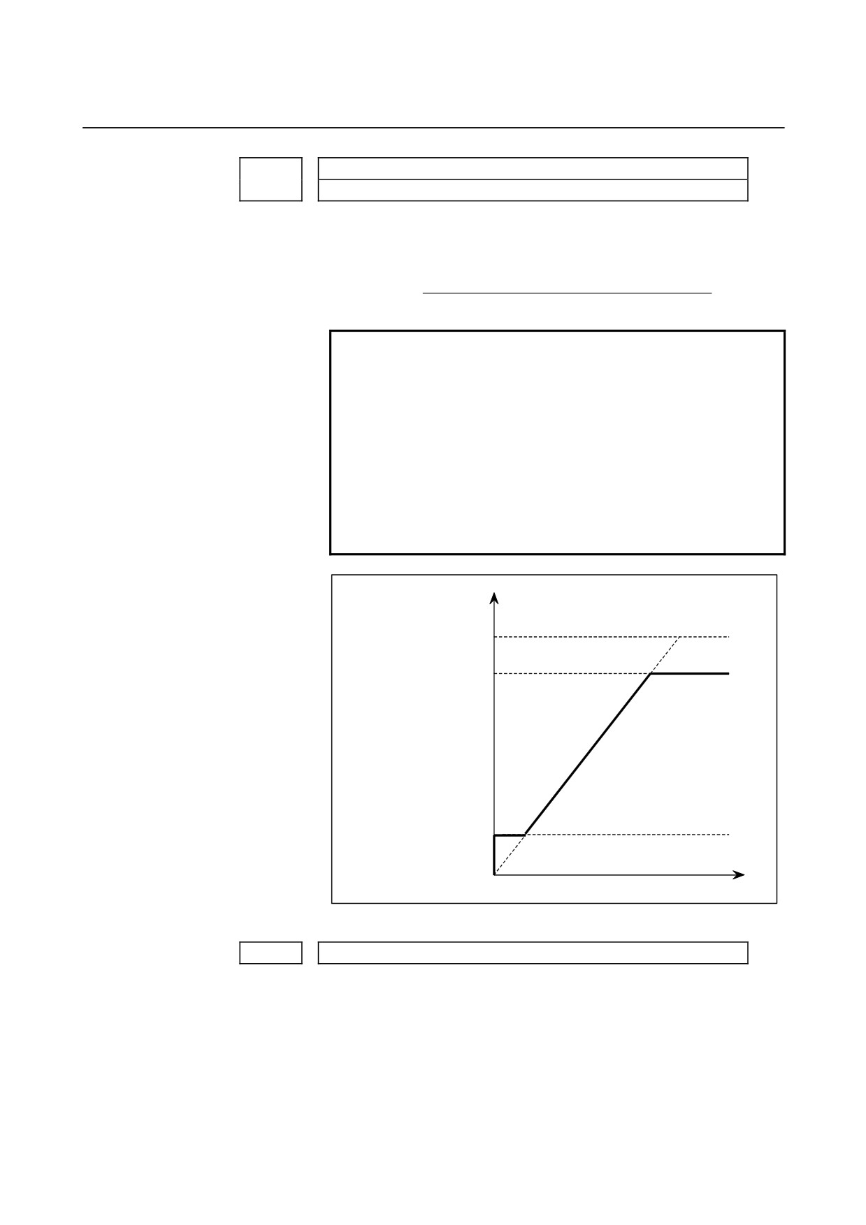
Spindle motor speed
Max. speed (4095, 10V)
Spindle motor max. clamp
speed (Parameter No.3736)
Spindle motor minimum clamp
speed (Parameter No.3735)
Spindle speed (S command)
Fig.4.20 (a) Maximum Clamp Speed of Spindle Motor
3740
Time elapsed prior to checking the spindle speed arrival signal
[Data type] Byte
[Unit of data] msec
[Valid data range]
0 to 225
Set the time elapsed from the execution of the S function up to the
checking of the spindle speed arrival signal.
- 198 -
B-64120EN/01
4.DESCRIPTION OF PARAMETERS
3741
Maximum spindle speed for gear 1
3742
Maximum spindle speed for gear 2
3743
Maximum spindle speed for gear 3
Maximum spindle speed for gear 4
3744
(Note)
[Data type] Two-word
[Unit of data] min-1
[Valid data range]
0 to 32767
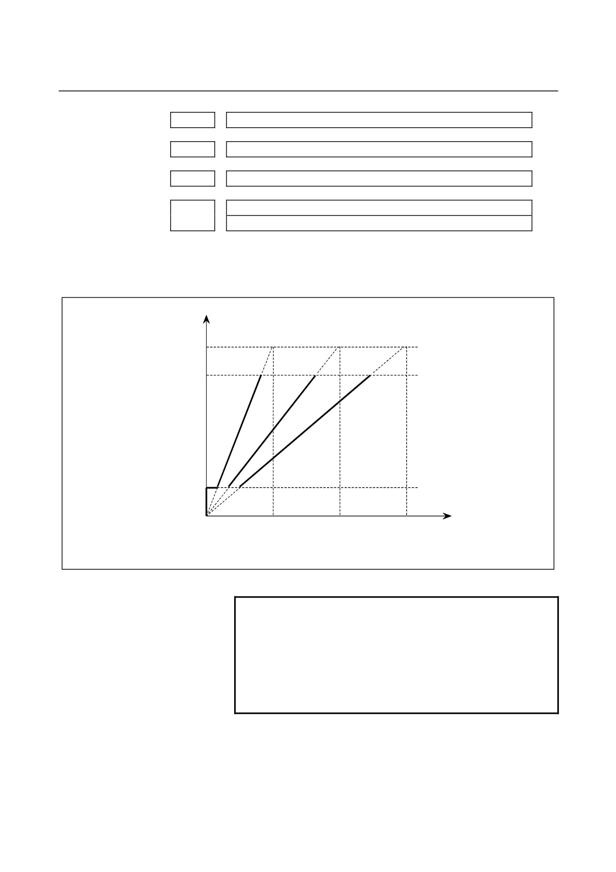
Set the maximum spindle speed corresponding to each gear.
Spindle motor speed
(Example for M series)
Max. speed (4095, 10V)
Spindle motor max. clamp
speed (Parameter No.3736)
Spindle motor minimum clamp
speed (Parameter No.3735)
Spindle speed
command (S
Gear 1
Gear 2
Gear 3
command)
Max. speed
Max. speed
Max. speed
(Parameter
(Parameter
(Parameter
No.3741)
No.3742)
No.3743)
Fig.4.20 (b) Maximum Spindle Speed Corresponding to Gear 1/2/3
NOTE
If a type-T gear shift scheme is selected for the M
series (with the constant surface speed control
option installed or parameter GTT (bit 4 of
parameter No. 3706) = 1), parameter No. 3744 is
usable also in the M series.
Note, however, that, even in this case, only up to
three main gear stages are usable for rigid tapping.
- 199 -
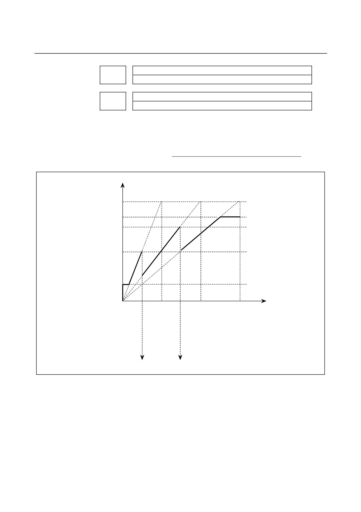
4.DESCRIPTION OF PARAMETERS
B-64120EN/01
3751
Spindle motor speed when switching from gear 1 to gear 2
3752
Spindle motor speed when switching from gear 2 to gear 3
[Data type] Word
[Valid data range]
0 to 4095
For gear switching method B, set the spindle motor speed when the
gears are switched.
Spindle motor speed when the gears are switched
Set value=
×4095
Maximum spindle motor speed
Spindle motor speed
Max. speed (4095, 10V)
Parameter No.3736
Spindle motor max. clamp speed
Parameter No.3752
Speed at gear 2-3 change point
Speed at gear 1-2 change point
Parameter No.3751
Spindle motor minimum clamp speed
Parameter No.3735
Spindle speed
command
Gear 1 max.
Gear 2
Gear 3
(S command)
speed
max. speed
max speed
parameter
parameter
parameter
No.3741
No.3742
No.3743
Gear 1-2
Gear 2-3
change point
change point
Fig.4.20 (c) Spindle Motor Speed at Gear 1-2/2-3 Change Point
- 200 -
B-64120EN/01
4.DESCRIPTION OF PARAMETERS
3761
Spindle speed when switching from gear 1 to gear 2 during tapping
3762
Spindle speed when switching from gear 2 to gear 3 during tapping
[Data type]
2-word
[Unit of data] min-1
[Valid data range]
0 to 32767
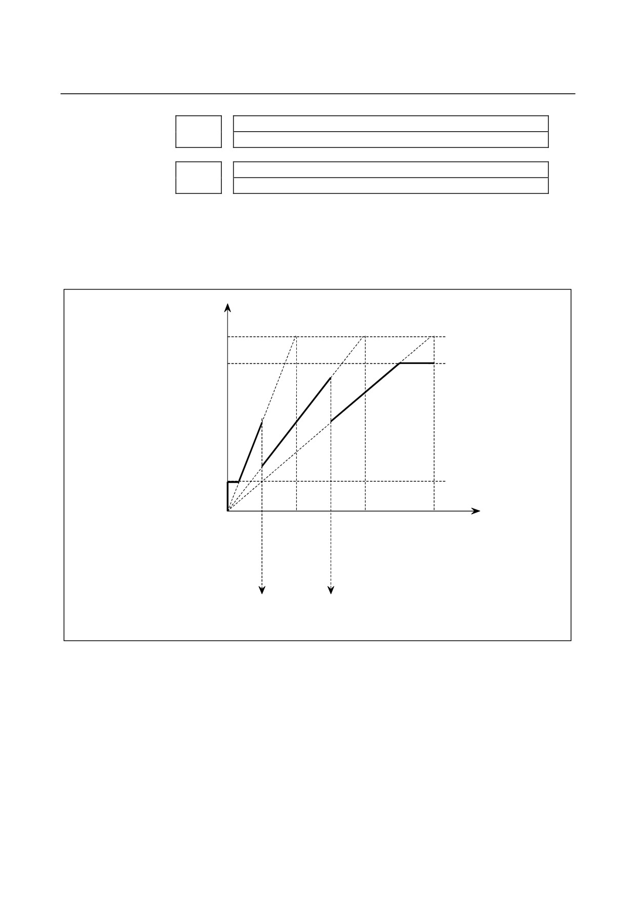
When method B is selected (SGT,#3 of parameter 3705, is set
to 1) for the tapping cycle gear switching method, set the spindle
speed when the gears are switched.
Spindle motor speed
Max. speed (4095, 10V)
Spindle motor max.
clamp speed
(Parameter No.3736)
Spindle motor minimum
clamp speed
(Parameter No.3735)
Spindle speed
Gear 1
Gear 2
Gear 3
command
Max. speed
Max. speed
Max. speed
(S command)
Parameter
Parameter
Parameter
No.3741
No.3742
No.3743
Gear 1-2
Gear 2-3
change point
change point
parameter
parameter
No.3761
No.3762
Fig.4.20 (d) Spindle Motor Speed at Gear 1-2/2-3 Change Point during Tapping
- 201 -