FANUC Series 0i-MODEL C, Series 0i Mate-MODEL C. PARAMETER MANUAL (B-64120EN/01) - page 6
4.DESCRIPTION OF PARAMETERS
B-64120EN/01
3017
Output time of reset signal RST
[Data type] Word
[Unit of data]
16 ms
[Valid data range]
0 to 255
To extend the output time of reset signal RST, the time to be added is
specified in this parameter.
RST signal output time = time required for reset + parameter × 16 ms
3030
Allowable number of digits for the M code
3031
Allowable number of digits for the S code
3032
Allowable number of digits for the T code
3033
Allowable number of digits for the B code
[Data type] Byte
[Valid data range]
1 to 8
Set the allowable numbers of digits for the M, S, T, and B codes.
NOTE
Up to 5 digits can be specified in the S code
- 142 -
B-64120EN/01
4.DESCRIPTION OF PARAMETERS
4.17
PARAMETERS OF DISPLAY AND EDIT (1 OF 2)
#7
#6
#5
#4
#3
#2
#1
#0
3100
COR
CEM
[Data type]
Bit
CEM
On screens such as the operation history screen and help screen, keys
on the MDI panel are indicated:
0 : In English.
1 : With graphics qualifying for CE marking. (A character generator
supporting graphics qualifying for CE marking is required.)
COR
Display
0 : Monochrome display
1 : Color display
NOTE
When using the 8.4" LCD, set this bit to 1.
#7
#6
#5
#4
#3
#2
#1
#0
3101
BGD
KBF
[Data type]
Bit
KBF
When the screen or mode is changed, the contents of the key-in buffer
are:
0 : Cleared.
1 : Not cleared.
NOTE
When KBF = 1, the contents of the key-in buffer
can all be cleared at one time by pressing the
key followed by the
key.
BGD
In background editing, a program currently selected in the foreground:
0 : Cannot be selected.
(BP/S alarm No.140 is issued disabling
selection.)
1 : Can be selected. (However, the program cannot be edited, only
displayed.)
- 143 -
4.DESCRIPTION OF PARAMETERS
B-64120EN/01
#7
#6
#5
#4
#3
#2
#1
#0
SPN
HNG
ITA
CHI
FRN
GRM
JPN
3102
DTH
SPN
HNG
ITA
CHI
FRN
GRM
JPN
#7
#6
#5
#4
#3
#2
#1
#0
3119
POR
#7
#6
#5
#4
#3
#2
#1
#0
3190
CH2
CZE
SWE
HUN
POL
NOTE
When this parameter has been set, the power must
be turned off before operation is continued.
[Data type]
Bit
Select the language to be used for the display.
CH2
CZE
SWE
HUN
POL
POR
DTH
SPN
HNG
ITA
CHI
FRN
GRM
JPN
Language
0
0
0
0
0
0
0
0
0
0
0
0
0
0
English
0
0
0
0
0
0
0
0
0
0
0
0
0
1
Japanese
0
0
0
0
0
0
0
0
0
0
0
0
1
0
German
0
0
0
0
0
0
0
0
0
0
0
1
0
0
French
Chinese (traditional
0
0
0
0
0
0
0
0
0
0
1
0
0
0
characters)
0
0
0
0
0
0
0
0
0
1
0
0
0
0
Italian
0
0
0
0
0
0
0
0
1
0
0
0
0
0
Korean
0
0
0
0
0
0
0
1
0
0
0
0
0
0
Spanish
0
0
0
0
0
0
1
0
0
0
0
0
0
0
Dutch
0
0
0
0
0
1
0
0
0
0
0
0
0
0
Portuguese
0
0
0
0
1
0
0
0
0
0
0
0
0
0
Polish
0
0
0
1
0
0
0
0
0
0
0
0
0
0
Hungarian
0
0
1
0
0
0
0
0
0
0
0
0
0
0
Swedish
0
1
0
0
0
0
0
0
0
0
0
0
0
0
Czech
Chinese (simplified
1
0
0
0
0
0
0
0
0
0
0
0
0
0
characters)
#7
#6
#5
#4
#3
#2
#1
#0
3103
NMH
[Data type]
Bit
NMH
The system alarm history screen is:
0 : Not displayed.
1 : Displayed.
- 144 -

B-64120EN/01
4.DESCRIPTION OF PARAMETERS
#7
#6
#5
#4
#3
#2
#1
#0
3104
DAC
DAL
DRC
DRL
PPD
MCN
[Data type]
Bit
MCN
Machine position
0 : Displayed according to the unit of output.
(The machine position is displayed regardless of whether metric
input or inch input is used; for a machine with metric output, the
machine position is displayed in mm, and for a machine with
inch output, the machine position is displayed in inches.)
1 : Displayed according to the unit of input.
(When input is made in mm, the machine position is displayed in
mm, and when input is made in inches, the machine position is
displayed in inches accordingly.)
PPD
Relative position display when a coordinate system is set
0 : Not preset
1 : Preset
NOTE
When PPD is set to 1 and the absolute position
display is preset by one of the following, the
relative position display is also preset to the same
value as the absolute position display:
1) The manual reference position return
2) Setting of a coordinate system by G92 (G50 for
T series G code system A)
DRL
Relative position
0 : The actual position displayed takes into account tool length
offset (M series) or tool offset (T series).
1 : The programmed position displayed does not take into account
tool length offset (M series) or tool offset (T series).
NOTE
When tool geometry compensation of the T system
is to be performed by shifting the coordinate
system (with bit 4 (LGT) of parameter No.5002 set
to 0), the programmed position, ignoring tool offset,
is displayed (with this parameter set to 1), but the
programmed position, ignoring tool geometry
compensation, cannot be displayed.
DRC
Relative position
0 : The actual position displayed takes into account cutter
compensation (M series) or tool nose radius compensation (T
series).
1 : The programmed position displayed does not take into account
cutter compensation (M series) or tool nose radius compensation
(T series).
- 145 -
4.DESCRIPTION OF PARAMETERS
B-64120EN/01
DAL
Absolute position
0 : The actual position displayed takes into account tool length
offset (M series) or tool offset (T series).
1 : The programmed position displayed does not take into account
tool length offset (M series) or tool offset (T series).
NOTE
When tool geometry compensation of the T system
is to be performed by shifting the coordinate
system (with bit 4 (LGT) of parameter No.5002 set
to 0), the programmed position, ignoring tool offset,
is displayed (with this parameter set to 1), but the
programmed position, ignoring tool geometry
compensation, cannot be displayed.
DAC
Absolute position
0 : The actual position displayed takes into account cutter
compensation (M series) or tool nose radius compensation (T
series).
1 : The programmed position displayed does not take into account
cutter compensation (M series) or tool nose radius compensation
(T series).
#7
#6
#5
#4
#3
#2
#1
#0
DPS
PCF
DPF
3105
SMF
DPS
PCF
DPF
[Data type]
Bit
DPF
Display of the actual speed on the current position display screen,
program check screen and program screen (MD1 mode)
0 : Not displayed
1 : Displayed
PCF
Addition of the movement of the PMC-controlled axes to the actual
speed display
0 : Added
1 : Not added
NOTE
For each setting, movement along any axis other
than those controlled by the CNC (see the
description of parameter No. 1010) is not reflected
in the actual speed display.
DPS
Actual spindle speed and T code
0 : Not always displayed
1 : Always displayed
- 146 -
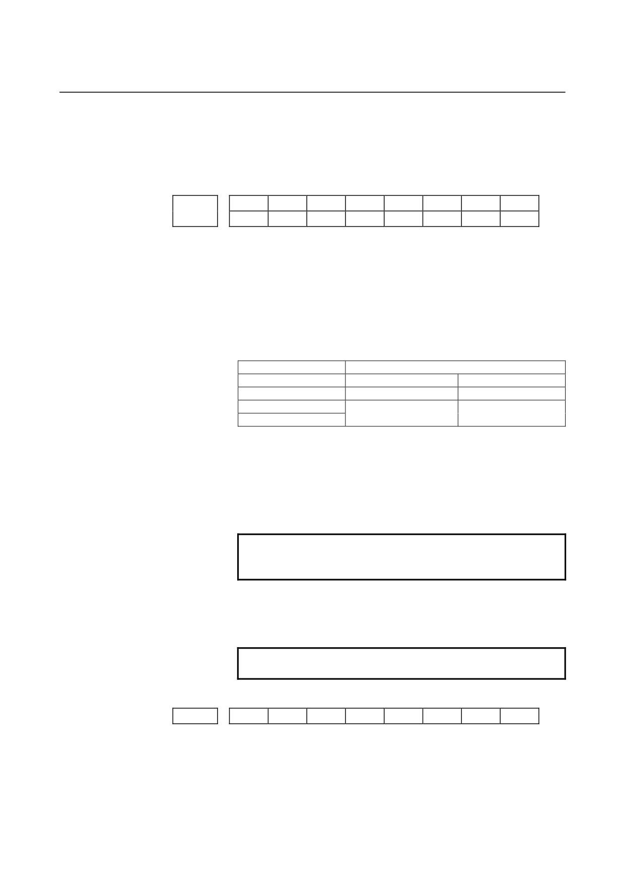
B-64120EN/01
4.DESCRIPTION OF PARAMETERS
SMF
During simplified synchronous control, movement along a slave axis
is: (see the parameter No.8311)
0 : Included in the actual speed display
1 : Not included in the actual speed display
#7
#6
#5
#4
#3
#2
#1
#0
OHS
SOV
OPH
SPD
GPL
3106
OHS
SOV
OPH
GPL
[Data type]
Bit
GPL
On the program list screen, the list-by-group function is:
0 : Disabled
1 : Enabled
SPD
Names for actual spindle speed values are displayed:
0 : Regardless of the selected spindle position coder
(in second
position coder selection signal (PC2SLC))
1 : Depending of the selected spindle position coder
(in second
position coder selection signal (PC2SLC))
SPD=0
SPD=1
Spindles 1 and 2
Spindles 1
Spindles 2
S
S1
S2
SACT
SACT1
SACT2
ACT, S
OPH
The operation history screen is:
0 : Not displayed.
1 : Displayed.
SOV
The spindle override value is:
0 : Not displayed.
1 : Displayed.
NOTE
This parameter is enabled only when bit 2 (DPS) of
parameter No.3105 is set to 1.
OHS
Operation history sampling is:
0 : Performed.
1 : Not performed.
NOTE
Normally, set 0 (sampling is performed).
#7
#6
#5
#4
#3
#2
#1
#0
3107
MDL
SOR
REV
DNC
[Data type]
Bit
DNC
Upon reset, the program display for DNC operation is:
0 : Not cleared
1 : Cleared
- 147 -
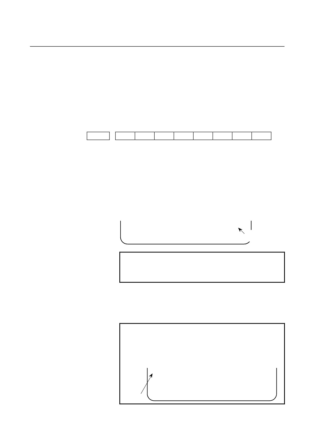
4.DESCRIPTION OF PARAMETERS
B-64120EN/01
REV
The actual speed in feed per revolution mode is displayed in:
0 : MM/MIN or INCH/MIN.
1 : MM/REV or INCH/REV.
SOR
Display of the program directory
0 : Programs are listed in the order of registration.
1 : Programs are listed in the order of program number.
MDL
Display of the modal state on the program display screen
0 : Not displayed
1 : Displayed (only in the MDI mode)
#7
#6
#5
#4
#3
#2
#1
#0
3108
JSP
SLM
WCI
PCT
[Data type]
Bit
PCT
On the program check screen, T code displayed
0 : is a T code specified in a program (T).
1 : is a T code specified by the PMC (HD. T/NX. T)
WCI
On the workpiece coordinate system screen, a counter input is:
0 : Disabled.
1 : Enabled.
SLM
The spindle load meter is:
0 : Not displayed.
1 : Displayed.
>_
Sxxxxx Lxxx%
EDIT *** *** ***
12:34:56
Display of the
[
] [
] [
] [
] [
] spindle load meter
NOTE
1 This parameter is enabled only when the DPS
parameter (bit 2 of parameter No.3105) is set to 1.
2 This is valid only for serial spindles.
JSP
On the current position display screen and program check screen, jog
feed is:
0 : Not displayed.
1 : Displayed.
NOTE
In manual operation mode, the jog feedrate is
displayed. In automatic operation mode, the dry run
feedrate is displayed. In each case, the feedrate to
which a manual feedrate override has been applied
is displayed.
JOG F
8000
PART COUNT
15
RUN TIME
1H17M
CYCLE TIME
1H15S
ACT.F
1000 MM/M
MEM STRT MTN ***
12:34:59
[
]
[
]
[
]
[
]
[
]
Jog
feedrate
- 148 -
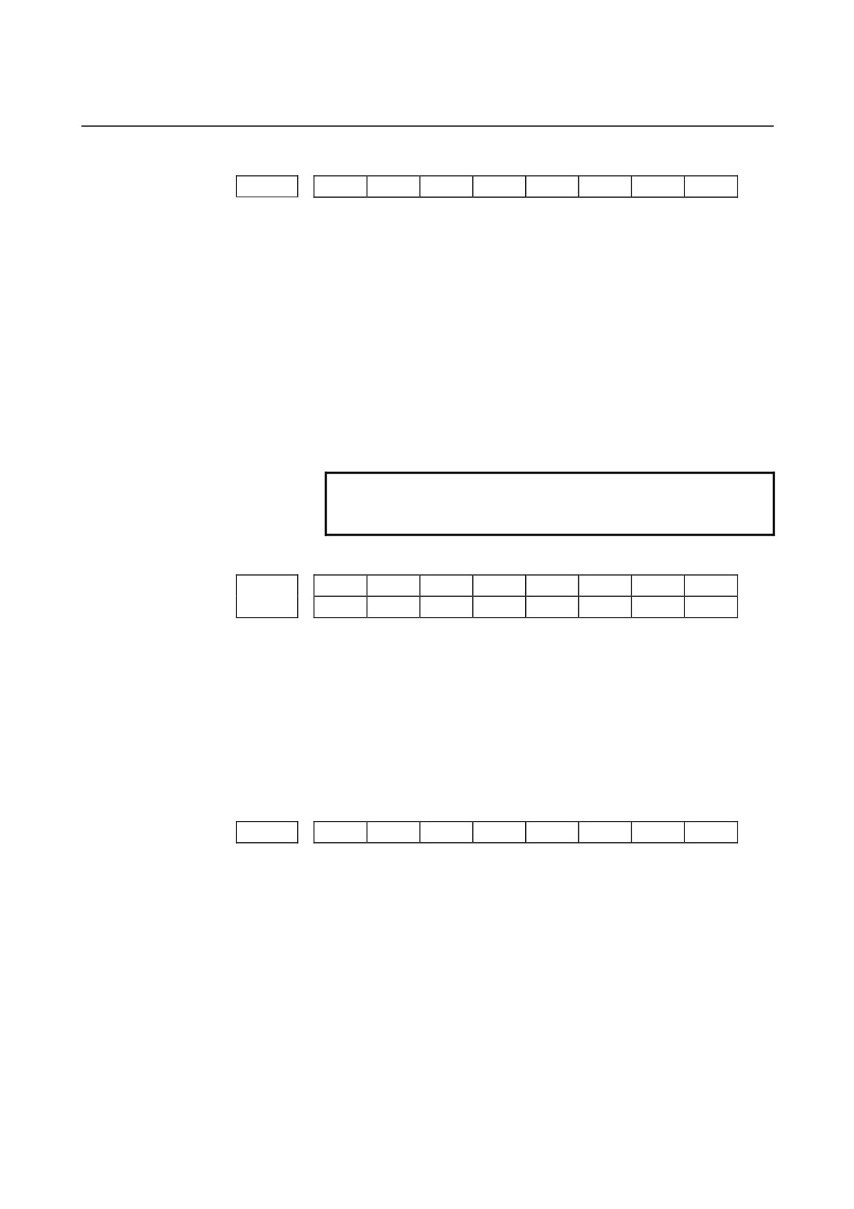
B-64120EN/01
4.DESCRIPTION OF PARAMETERS
#7
#6
#5
#4
#3
#2
#1
#0
3109
RHD
IKY
DWT
[Data type]
Bit
DWT
Characters G and W in the display of tool wear/geometry
compensation amount
0 : The characters are displayed at the left of each number.
1 : The characters are not displayed.
IKY
On the tool offset screen and workpiece shift screen (T series), soft
key [INPUT] is:
0 : Displayed.
1 : Not displayed.
RHD
When a manual handle interrupt is generated, the relative position
display is:
0 : Not updated.
1 : Updated.
NOTE
This parameter is enabled when the INH parameter
(bit 2 of parameter No.7100) is 1.
#7
#6
#5
#4
#3
#2
#1
#0
AHC
OFA
3110
AHC
[Data type]
Bit
OFA
The axis names on the offset screen, Y-axis offset screen, and 4th axis
offset screen are:
0 : Always X, Z, and Y.
1 : As specified by parameter No. 1020.
AHC
With a soft key, the alarm history:
0: Can be cleared.
1: Cannot be cleared.
#7
#6
#5
#4
#3
#2
#1
#0
3111
NPA
OPS
OPM
SVP
SPS
SVS
[Data type]
Bit
SVS
Servo tuning screen
0 : Not displayed
1 : Displayed
SPS
Spindle tuning screen
0 : Not displayed
1 : Displayed
SVP
Synchronization errors displayed on the spindle tuning screen
0 : Instantaneous values are displayed.
1 : Peak-hold values are displayed.
OPM
Operating monitor
0 : Not displayed
1 : Displayed
OPS
The speedometer on the operating monitor screen indicates:
- 149 -
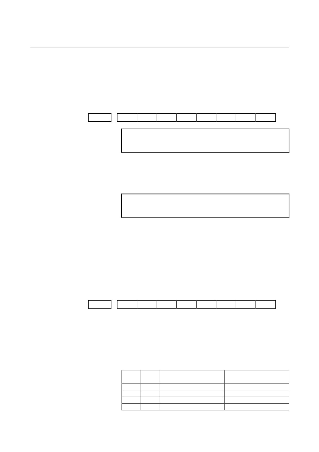
4.DESCRIPTION OF PARAMETERS
B-64120EN/01
0 : Spindle motor speed
1 : Spindle speed
NPA
Action taken when an alarm is generated or when an operator message
is entered
0 : The display shifts to the alarm or message screen.
1 : The display does not shift to the alarm or message screen.
#7
#6
#5
#4
#3
#2
#1
#0
3112
OPH
EAH
OMH
SGD
NOTE
When this parameter is set, the power must be
turned off before operation is continued.
[Data type]
Bit
SGD
Servo waveform
0 : Not displayed
1 : Displayed
NOTE
If SGD is set to 1, no graphic display other than
servo waveform display is done.
OMH
The external operator message history screen is:
0 : Not displayed.
1 : Displayed.
EAH
Messages of the external alarm/macro alarm in alarm history:
0 : Not recorded
1 : Recorded
OPH
The operation history log function is:
0 : Displayed.
1 : Enable.
#7
#6
#5
#4
#3
#2
#1
#0
3113
MS1
MS0
MHC
[Data type]
Bit
MHC
External operator message history data:
0 : Cannot be cleared.
1 : Can be cleared.
(Such data can be cleared using the [CLEAR] soft key.)
MS0, MS1
A combination of the number of characters preserved as external
operator message history data and the number of history data items is
set according to the table below.
Number of history data
Number of history data
MS1
MS0
characters
items
0
0
255
8
0
1
200
10
1
0
100
18
1
1
50
32
- 150 -
B-64120EN/01
4.DESCRIPTION OF PARAMETERS
NOTE
When the values of MS0 and MS1 are changed, all
preserved external operator message history data
is cleared.
#7
#6
#5
#4
#3
#2
#1
#0
3114
ICS
IUS
IMS
ISY
IOF
IPR
IPO
[Data type]
Bit
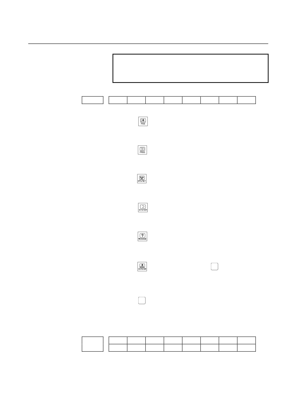
IPO
When the
function key is pressed while the position display
screen is being displayed:
0 : The screen is changed.
1 : The screen is not changed.
IPR
When the
function key is pressed while the program screen is
being displayed:
0 : The screen is changed.
1 : The screen is not changed.
IOF
When the
function key is pressed while the offset/setting screen
is being displayed:
0 : The screen is changed.
1 : The screen is not changed.
ISY
When the
function key is pressed while the system screen is
being displayed:
0 : The screen is changed.
1 : The screen is not changed.
IMS
When the
function key is pressed while the message screen is
being displayed:
0 : The screen is changed.
1 : The screen is not changed.
GRAPH
IUS
When the
(using small MDI unit) or
(using standard MDI
unit) function key is pressed while the custom or graphic screen is
being displayed:
0 : The screen is changed.
1 : The screen is not changed.
CUSTOM
ICS
When the
(using standard MDI unit) function key is pressed
while the custom screen is being displayed:
0 : The screen is changed.
1 : The screen is not changed.
#7
#6
#5
#4
#3
#2
#1
#0
NDFx
SFMx
NDAx
NDPx
3115
D10x
NDFx
NDAx
NDPx
[Data type]
Bit axis
NDPx
Display of the current position for each axis
0 : The current position is displayed.
1 : The current position is not displayed.
- 151 -
4.DESCRIPTION OF PARAMETERS
B-64120EN/01
NDAx
Position display using absolute coordinates and relative coordinates is:
0 : Performed.
1 : Not performed.
(Machine coordinates are displayed.)
SFMx
In current position display, subscripts are:
0 : Added to the absolute, relative, and machine coordinate axis
names.
1 : Assed only to the machine coordinate axis names.
NDFx
To the actual speed display, axis movement data is:
0 : Added.
1 : Not added.
NOTE
Even if the PCF parameter (bit 1 of parameter
No.3105) is set to 0, so as to add PMC controlled
axis movement data to the actual speed display,
the movement data for a PMC controlled axis for
which NDFx is set to 1 is not added to the actual
speed display.
D10x
The current positions (absolute position, relative position, machine
position, remaining travel, and travel by manual handle interrupt), and
workpiece zero-point offset are:
0 : Displayed as usual.
(Not multiplied by ten.)
1 : Multiplied by ten, and displayed.
Example:
The current position on the Y-axis is multiplied by ten and
displayed.
X 1.2345 → X 1.2345
Y 1.2345 → Y 12.345
Z 1.2345 → Z 1.2345
- 152 -
B-64120EN/01
4.DESCRIPTION OF PARAMETERS
#7
#6
#5
#4
#3
#2
#1
#0
3116
MDC
T8D
COA
FOV
PWR
[Data type]
Bit
PWR
Alarm No.100 (parameter enable) :
0 : Clear by
+
key
1 : Clear by
key
FOV
In the field of specified feedrate F on the program check screen,
0 : The specified feedrate is displayed.
1 :
(Specified feedrate) x (override) is displayed.
COA
While an external alarm state is present or while an external message
is being displayed, automatic screen erasure is:
0 : Performed.
1 : Not performed.
T8D
T codes that are always displayed are displayed with:
0 : Four digits.
1 : Eight digits.
This parameter expands the T code display to eight digits for
the continuous S or T display (bit 2 (DPS) of parameter No. 3105 is
set to 1).
MDC
Maintenance information by operating soft key :
0 : All clear disable.
1 : All clear enable.
#7
#6
#5
#4
#3
#2
#1
#0
ANS
SPP
3117
ANS
SMS
NOTE
When this parameter is set, the power must be
turned off before operation is continued.
[Data type]
Bit
SMS
On the program check screen, the soft key to enable or disable the
graph of spindle speed and load is:
0 : Not displayed.
1 : Displayed.
SPP
On the diagnostic screen, spindle position data (the number of pulses
from the position coder, detected after the detection of the
one-revolution signal) is:
0 : Not displayed.
1 : Displayed.
(Diagnostic Nos. 445 to 447)
ANS
The subscript of each axis name set in parameter No.
3131 is
displayed:
0 : Only when the current position is displayed.
1 : On the parameter screen, diagnosis screen, alarm screen, and
alarm history screen as well as when the current position is
displayed.
#7
#6
#5
#4
#3
#2
#1
#0
- 153 -
4.DESCRIPTION OF PARAMETERS
B-64120EN/01
3118
AS2
AS1
[Data type]
Bit
AS1 to AS2
When the actual spindle speeds (SACT) of the first spindle and second
spindle are displayed, each value is:
0 : The value calculated based on the feedback pulses from the
position coder.
1 : The value calculated from the spindle motor speed (the same as
the spindle speed displayed on the operating monitor screen).
#7
#6
#5
#4
#3
#2
#1
#0
3119
NVG
TPA
POR
NOTE
When this parameter is set, the power must be
turned off before operation is continued.
[Data type]
Bit
POR
Display in Portuguese is:
0: Disabled.
1: Enabled.
TAP
When the external touch panel interface option is available,
the
external touch panel is:
0: Enabled.
1: Disabled.
NVG
When a color display device is used, VGA mode is:
0: Used.
1: Not used.
Time from the output of an alarm to the termination of sampling (waveform
3120
diagnosis function)
[Data type]
Word
[Unit of data]
ms
[Valid data range]
1 to 32760
When the waveform diagnosis function is used, this parameter sets the
time form the output of a servo alarm until data collection. Storage
operation is stopped because of the alarm.
(This means that the
termination of data collection can be delayed by a specified time.)
3121
Store-type waveform diagnosis data select (waveform diagnosis function)
[Data type]
Byte
[Valid data range]
0 to 1
The six types of sampling data in store-type waveform diagnosis are:
0 : Thermal simulation data.
1 : Spindle load meter.
- 154 -
B-64120EN/01
4.DESCRIPTION OF PARAMETERS
3122
Time interval used to record time data in operation history
[Data type]
Word
[Unit of data]
min
[Valid data range]
0 to 1439
Time data is recorded in operation history at set intervals.
When 0 is specified in this parameter, 10 minutes is assumed as the
default. However, note that time data is not recorded if there is no data
to be recorded at the specified time.
3123
Time until automatic screen clear function is applied
[Data type]
Byte
[Unit of data]
min
[Valid data range]
1 to 255
This parameter specifies the period that must elapse before the
automatic screen clear function is applied.
This parameter is valid when bit 1 (COK) of parameter No. 3208 is 0.
However, the automatic screen clear function is disabled if 0 is set in
this parameter.
NOTE
When the automatic screen clear function is
enabled, manual screen clearing with
CAN+FUNCTION is disabled.
#7
#6
#5
#4
#3
#2
#1
#0
3124
D08
D07
D06
D05
D04
D03
D02
D01
#7
#6
#5
#4
#3
#2
#1
#0
3125
D16
D15
D14
D13
D12
D11
D10
D09
#7
#6
#5
#4
#3
#2
#1
#0
3126
D24
D23
D22
D21
D20
D19
D18
D17
#7
#6
#5
#4
#3
#2
#1
#0
3127
D25
[Data type]
Bit
Dxx (xx: 01 to 25)
When modal G code is displayed on the program check screen, the xx
group G code is:
0 : Displayed.
1 : Not displayed.
- 155 -
4.DESCRIPTION OF PARAMETERS
B-64120EN/01
3131
Subscript of each axis name
[Data type]
Byte axis
This parameter specifies a subscript (one character) of each axis name
with a code.
The subscript (one character) specified in this parameter is displayed
following the axis name.
NOTE
For characters and codes, see the correspondence
table in Appendix A.
[Example]
When the axes include X, Z, C, and Y, and the following settings
are made, the axis names are displayed as XA, Z1, CS, and Y1:
Parameter 3131x
65 (A)
Parameter 3131z
49 (1)
Parameter 3131c
83 (S)
Parameter 3131y
49 (1)
Axis name (absolute coordinate) for current position display
3132
Axis name (relative coordinate) for current position display
3133
[Data type]
Byte axis
[Valid data range]
0 to 255
These parameters set the axis name for current position display.
When G code system B or C is used, the axis name set in parameter
No.3132 is used for both absolute and relative coordinate axes.
The values set in these parameters are used only for display.
For a command address, the axis name set in parameter No.1020 is
used.
When 0 is specified in these parameters, the value set in parameter
No.1020 is used.
Axis display order on workpiece coordinate system screen and workpiece
3134
shift screen
[Data type]
Byte axis
[Valid data range]
0, 1 to the number of controlled axes
This parameter specifies the order in which axes are displayed on the
workpiece coordinate system screen and workpiece shift screen (for T
series).
When the parameters of all axes are set to 0, all axes are displayed.
When the parameters of some axes are set, the axes for which a value
of 0 is specified do not appear. The displayed axes are consecutive
without spaces being left for non-displayed axes.
- 156 -
B-64120EN/01
4.DESCRIPTION OF PARAMETERS
3151
Number of the axis for which the 1st load meter for the servo motor is used
3152
Number of the axis for which the 2nd load meter for the servo motor is used
3153
Number of the axis for which the 3rd load meter for the servo motor is used
3154
Number of the axis for which the 4th load meter for servo motor is used
[Data type]
Byte
[Valid data range]
0, 1, . . . , the number of control axes
Set the numbers of the axes for which measurement values on the load
meters for the four servo motors are displayed. Set the parameters to 0
for those axes for which a load meter need not be displayed.
3163
Time required to smooth the spindle load meter readings
[Data type]
Byte
[Unit of data]
32 ms
[Valid data range]
0 to 32
When the spindle load meter reading is displayed (see the description
of the SLM parameter (bit 6 of parameter No.3108)), smoothing can
be applied to the spindle load meter reading to prevent flickering.
This parameter sets the time width for smoothing.
Setting
Time for smoothing (msec)
0
256
1
32
2
64
3
96
:
:
32
1024
Each smoothing operation is performed for a time width of between
32 ms and 1024 ms.
#7
#6
#5
#4
#3
#2
#1
#0
3190
CH2
CZE
SWE
HUN
POL
NOTE
When this parameter is set, the power must be
turned off before operation is continued.
[Data type]
Bit
POL
Display in Polish is:
0 : Not performed.
1 : Performed.
HUN
Display in Hungarian is:
0 : Not performed.
1 : Performed.
SWE
Display in Swedish is:
0 : Not performed.
1 : Performed.
CZE
Display in Czech is:
- 157 -

4.DESCRIPTION OF PARAMETERS
B-64120EN/01
0 : Not performed.
1 : Performed.
CH2
Display in Chinese (simplified Chinese characters)
0 : Not performed.
1 : Performed.
#7
#6
#5
#4
#3
#2
#1
#0
CAP
FSS
STS
FPS
3191
CAP
STS
WKI
[Data type]
Bit
FPS
The unit of values in the display of actual speeds in feed per
revolution mode is:
0 : Feedrate per minute.
1 : Feedrate per spindle rotation.
This parameter is valid when bit 3 (REV) of parameter No. 3107 is set
to 1.
WKI
On the workpiece coordinate system setting screen, the soft key
[INPUT] is:
0 : Displayed.
1 : Not displayed.
STS
When data is input on the setting screen, a confirmation message is:
0 : Not displayed.
1 : Displayed.
FSS
The feedrate display is switched:
0 : In accordance with the operation state.
1 : By a DI signal.
CAP
The position of soft key [ALL] that appears by pressing soft key
[ERASE] for clearing offset values on the offset screen is:
0 : Not changed.
1 : Changed.
NOTE
Soft key [ALL] is displayed in the same position as
soft key [ERASE]. Therefore, when soft key
[ERASE] is pressed twice by mistake, offset data
may be all cleared.
Since the position of soft key [ALL] is changed
when this parameter is set to 1, it is possible to
prevent offset data from being all cleared even
when soft key [ERASE] is pressed twice by
mistake.
- 158 -

B-64120EN/01
4.DESCRIPTION OF PARAMETERS
#7
#6
#5
#4
#3
#2
#1
#0
3192
RDM
[Data type]
Bit
RDM
The machine remote diagnostic message notification function is:
0 : Enabled.
1 : Disabled.
#7
#6
#5
#4
#3
#2
#1
#0
3195
CPR
[Data type]
Bit
CPR
Pressing the [SYSTEM] function key:
0 : Displays the parameter setting assistance screen.
1 : Does not display the parameter setting assistance screen.
#7
#6
#5
#4
#3
#2
#1
#0
3201
MIP
NPE
N99
PUO
REP
RAL
RDL
[Data type]
Bit
RDL
When a program is registered by input/output device external control
0 : The new program is registered following the programs already
registered.
1 : All registered programs are deleted, then the new program is
registered. Note that programs which are protected from being
edited are not deleted.
RAL
When programs are registered through the reader/puncher interface
0 : All programs are registered.
1 : Only one program is registered.
REP
Action in response to an attempt to register a program whose number
is the same as that of an existing program
0 : An alarm is generated.
1 : The existing program is deleted, then the new program is
registered. Note that if the existing program is protected from
being edited, it is not deleted, and an alarm is generated.
PUO
When address O of a program number is output in ISO code:
0 : ":" is output.
1 : "O" is output.
N99
With an M99 block, when bit 6 (NPE) of parameter No.3201 = 0,
program registration is assumed to be:
0 : Completed
1 : Not completed
NPE
With an M02, M30, or M99 block, program registration is assumed to
be:
0 : Completed
1 : Not completed
MIP
Program registration by external start signal (MINP) :
0 : Not performed.
1 : Performed.
#7
#6
#5
#4
#3
#2
#1
#0
- 159 -
4.DESCRIPTION OF PARAMETERS
B-64120EN/01
3202
PSR
CPD
NE9
OSR
CND
OLV
NE8
[Data type]
Bit
NE8
Editing of subprograms with program numbers 8000 to 8999
0 : Not inhibited
1 : Inhibited
The following edit operations are disabled:
(1) Program deletion
(Even when deletion of all programs is specified,
programs with program numbers 8000 to 8999 are not deleted.)
(2) Program output (Even when outputting all programs is specified,
programs with program numbers 8000 to 8999 are not output.)
(3) Program number search
(4) Program editing of registered programs
(5) Program registration
(6) Program collation
(7) Displaying programs
OLV
When a program other than the selected program is deleted or output:
0 : The display of the selected program is not held.
1 : The display of the selected program is held.
CND
By using the [CONDENSE] soft key on the program directory screen,
the program condensing operation is:
0 : Not performed. (The [CONDENSE] soft key is not displayed.)
1 : Performed.
OSR
In programming number search, when pressing soft key [O-SEARCH]
without inputting program number by key :
0 : Search the following program number
1 : Operation is invalid
NE9
Editing of subprograms with program numbers 9000 to 9999
0 : Not inhibited
1 : Inhibited
The following program editing during operation is invalid.
(1) Program deletion
(Even when deletion of all programs is
specified, programs with program numbers 9000 to 9999 are not
deleted.)
(2) Program punching
(Even when punching of all programs is
specified, programs with program numbers 9000 to 9999 are not
punched.)
(3) Program number search
(4) Program editing after registration
(5) Program registration
(6) Program collation
(7) Displaying programs
CPD
When an NC program is deleted, a confirmation message and
confirmation soft key are:
0 : Not output.
1 : Output.
PSR
Search for the program number of a protected program
0 : Disabled
1 : Enabled
- 160 -
B-64120EN/01
4.DESCRIPTION OF PARAMETERS
NOTE
If this parameter is set, a protected program is also
displayed.
#7
#6
#5
#4
#3
#2
#1
#0
3203
MCL
MER
MIE
[Data type]
Bit
MIE
After MDI operation is started, program editing during operation is:
0 : Enabled
1 : Disabled
MER
When the last block of a program has been executed at single block
operation in the MDI mode, the executed block is:
0 : Not deleted
1 : Deleted
NOTE
When MER is set to 0, the program is deleted if the
end-of-record mark (%) is read and executed. (The
mark % is automatically inserted at the end of a
program.)
MCL
Whether a program prepared in the MDI mode is cleared by reset
0 : Not deleted
1 : deleted
#7
#6
#5
#4
#3
#2
#1
#0
3204
MKP
EXK
PAR
[Data type]
Bit
PAR
When a small keyboard is used, characters "[" and "]" are:
0 : Used as "[" and "]".
1 : Used as "(" and ")".
EXK
The input character extension function is:
0 : Not used. ([C-EXT] soft key is displayed.)
1 : Used.
NOTE
The [C-EXT] soft key is used to select an operation
on the program screen. This soft key enables the
entry of "(", ")", and "@" using soft keys. This soft
key is useful when using the small MDI keyboard,
which does not have the "(", ")", and "@" keys.
MKP
When M02, M30, or EOR(%) is executed during MDI operation, the
created MDI program is:
0 : Erased automatically.
1 : Not erased automatically.
- 161 -
4.DESCRIPTION OF PARAMETERS
B-64120EN/01
NOTE
If the MER parameter (bit 6 of parameter No.3203)
is 1, executing the last block provides a choice of
whether to automatically erase a created program.
#7
#6
#5
#4
#3
#2
#1
#0
3205
MCK
BGC
OSC
PNS
CMO
CHG
COL
[Data type]
Bit
COL
When a program is displayed or output, any colons
(:) in the
comments of the program are:
0 : Converted to letter O
1 : Displayed or output as is
CHG
When the change function of the extended edit function is used:
0 : Once the user has decided whether to make a change, the cursor
is moved to the target position.
1 : The cursor is moved to the change source, after which the user
can choose whether to make a change.
CMO
In extended tape editing, the copy or move operation:
0 : Is performed in the usual way.
1 : Can also copy or move data from a program to a key-in buffer in
units of words.
PNS
On the program screen, a search by a cursor key is:
0 : Performed.
1 : Not performed.
OSC
On the offset screen, offset value erasure by a soft key is:
0 : Enabled.
1 : Disabled.
BGC
When background editing starts:
0 : The edit program is initialized (no program is selected).
1 : The previous edit program is edited continuously.
(Continuous editing is allowed only when neither editing nor
operation is being performed in the foreground (that is, when
continuation is possible).)
MCK
The system tape memory check function is:
0 : Not used.
1 : Used.
(This setting is inhibited.)
#7
#6
#5
#4
#3
#2
#1
#0
3206
NS2
PHS
MIF
[Data type]
Bit
MIF
Editing of the maintenance information screen is:
0 : Not prohibited.
1 : Prohibited.
PHS
The selection of an operation history signal and parameters
(No.
12801 to No. 128900) are:
0 : Not linked.
1 : Linked.
NS2
The CNC screen display function dual display is:
0 : Not used.
- 162 -
B-64120EN/01
4.DESCRIPTION OF PARAMETERS
1 : Used.
#7
#6
#5
#4
#3
#2
#1
#0
3207
OM4
NOTE
When this parameter has been set, the power must
be turned off before operation is continued.
[Data type]
Bit
OM4
A message displayed on the external operator message screen can
have:
0 : Up to 256 characters, and just a single message can be displayed.
1 : Up to 64 characters, and up to four messages can be displayed.
#7
#6
#5
#4
#3
#2
#1
#0
3208
COK
SKY
[Data type]
Bit
SKY
The function key [SYSTEM] on the MDI panel is:
0 : Enabled.
1 : Disabled.
COK
The automatic screen erase function is:
0 : Enabled.
1 : Disabled.
NOTE
If this parameter is set to 1, manual screen erasure
by the CAN + FUNCTION key is enabled,
irrespective of the setting of parameter No. 3123.
#7
#6
#5
#4
#3
#2
#1
#0
3209
UPP
NFU
MPD
[Data type]
Bit
MPD
When a subprogram is executed, the main program number is:
0 : Not displayed.
1 : Displayed.
NFU
In the screen erase function/automatic screen erase function, when the
function key is pressed to erase or display a screen, switching of
screen with the function key is:
0 : Performed.
1 : Not performed.
UPP
The FOCAS1/ETHERNET cnc_upload3( ) function:
0 : Does not upload the protected programs.
1 : Uploads the protected programs if a search is possible.
3210
Password
[Data type]
2-word axis
- 163 -

4.DESCRIPTION OF PARAMETERS
B-64120EN/01
This parameter sets a password for protecting program Nos.
9000 to 9999. When a value other than zero is set in this parameter
and this value differs from the keyword set in parameter No.3211, bit
4 (NE9) of parameter No.3202 for protecting program Nos. 9000 to
9999 is automatically set to 1. This disables the editing of program
Nos. 9000 to 9999. Until the value set as the password is set as a
keyword, NE9 cannot be set to
0 and the password cannot be
modified.
NOTE
1 The state where password ≠ 0 and password ≠
keyword is referred to as the locked state. When an
attempt is made to modify the password by MDI
input operation in this state, the warning message
"WRITE PROTECTED" is displayed to indicate that
the password cannot be modified. When an
attempt is made to modify the password with G10
(programmable parameter input), P/S alarm
No.231 is issued.
2 When the value of the password is not 0, the
parameter screen does not display the password.
Care must be taken in setting a password.
3211
Keyword
[Data type]
2-word
When the value set as the password (set in parameter No.3210) is set
in this parameter, the locked state is released and the user can now
modify the password and the value set in bit 4 (NE9) of parameter
No.3202.
NOTE
The value set in this parameter is not displayed.
When the power is turned off, this parameter is set
to 0.
3216
Increment in sequence numbers inserted automatically
The following parameter can be set at "Setting screen".
[Data type]
Word
[Valid data range]
0 to 9999
Set the increment for sequence numbers for automatic sequence
number insertion (when SEQ, #5 of parameter 0000, is set to 1.)
- 164 -
B-64120EN/01
4.DESCRIPTION OF PARAMETERS
#7
#6
#5
#4
#3
#2
#1
#0
3232
ND9
ND8
[Data type]
Bit
ND8
While program No. 8000 to 8999 is being executed as a subprogram
or macro program, display on the program screen is:
0 : Not disabled.
1 : Disabled.
ND9
While program No. 9000 to 9999 is being executed as a subprogram
or macro program, display on the program screen is:
0 : Not disabled.
1 : Disabled.
3241
Character blinking in the AI advanced preview control mode or AI contour
control mode (first character)
3242
Character blinking in the AI advanced preview control mode or AI contour
control mode (second character)
3243
Character blinking in the AI advanced preview control mode or AI contour
control mode (third character)
3244
Character blinking in the AI advanced preview control mode or AI contour
control mode (fourth character)
3245
Character blinking in the AI advanced preview control mode or AI contour
control mode (fifth character)
3246
Character blinking in the AI advanced preview control mode or AI contour
control mode (sixth character)
3247
Character blinking in the AI advanced preview control mode or AI contour
control mode (seventh character)
[Data type]
Byte
[Valid data range]
0 to 255
Set the character codes of characters blinking in the AI advanced
preview control mode or AI contour control mode.
NOTE
1 Set character codes according to the character
code list in Appendix A.
2 If 0 is set, "AICC" blinks when the AI contour
control option is provided, and when the option is
not provided, "AIAPC" blinks.
- 165 -

4.DESCRIPTION OF PARAMETERS
B-64120EN/01
#7
#6
#5
#4
#3
#2
#1
#0
3290
KEY
MCM
IWZ
WZO
MCV
GOF
WOF
[Data type]
Bit
WOF
Setting the tool offset value by MDI key input is:
0 : Not disabled
1 : Disabled (With parameter No.3294 and No.3295, set the offset
number range in which updating the setting is to be disabled.)
GOF
Setting the tool offset value by MDI key input is:
0 : Not disabled
1 : Disabled (With parameter No.3294 and No.3295, set the offset
number range in which updating the setting is to be disabled.)
MCV
Macro variable setting by MDI key input is:
0 : Not disabled
1 : Disabled
NOTE
If this parameter is set to 1, input of tool life
management data by MDI is also disabled.
WZO
Setting a workpiece zero point offset value by MDI key input is:
0 : Not disabled
1 : Disabled
IWZ
Setting a workpiece zero point offset value or workpiece shift value
(T-series) by MDI key input in the automatic operation activation or
halt state is:
0 : Not disabled
1 : Disabled
MCM
The setting of custom macros by MDI key operation is:
0 : Enabled regardless of the mode.
1 : Enabled only in the MDI mode.
KEY
For memory protection keys:
0 : The KEY1, KEY2, KEY3, and KEY4 signals are used.
1 : Only the KEY1 signal is used.
- 166 -
B-64120EN/01
4.DESCRIPTION OF PARAMETERS
NOTE
The functions of the signals depend on whether
KEY=0 or KEY=1.
When KEY = 0:
- KEY1: Enables a tool offset value and a
workpiece zero point offset value to be
input.
- KEY2: Enables setting data and macro variables
to be input.
- KEY3: Enables program registration and editing.
- KEY4: Enables PMC data (counter and data
table) to be input.
When KEY = 1:
- KEY1: Enables program registration and editing,
and enables PMC parameter input.
- KEY2 to KEY4: Not used
#7
#6
#5
#4
#3
#2
#1
#0
3291
WPT
[Data type]
Bit
WPT
The input of the tool wear compensation amount is:
0 : Enabled according to memory protection key signal KEY1.
1 : Always enabled.
#7
#6
#5
#4
#3
#2
#1
#0
3292
PK5
[Data type]
Bit
PK5
The KEYPRM signal (memory protection signal, parameter write
setting) is:
0 : Disabled.
1 : Enabled.
If this parameter is set to
1, PWE on the setting screen becomes
invalid, and the KEYPRM signal <G046#0> is used to make memory
protection and parameter write settings.
- 167 -
4.DESCRIPTION OF PARAMETERS
B-64120EN/01
3294
Start number of tool offset values whose input by MDI is disabled
Number of tool offset values (from the start number) whose input by MDI is
3295
disabled
[Data type]
Word
To prevent tool offset values from being changed by MDI key input
operation using bit 0 (WOF) of parameter No. 3290 and bit 1 (GOF)
of parameter No. 3290, set the inhibited range in this parameter.
Set the start offset number of the tool offset values to be protected in
parameter No. 3294 and the number of tool offset values from the start
in parameter No. 3295.
When 0 or a negative value is set in parameter No.3294 or parameter
No.3295, no modification of the tool offset values is allowed.
When the value set with parameter No.3294 is greater than the
maximum tool offset count, no modification is allowed.
[Example]
The following setting disables the modification of both the tool
geometry compensation values and tool wear compensation
values corresponding to offset numbers 51 to 60:
Bit 1 (GOF) of parameter No.3290=1 (Disables tool offset value
modification.)
Bit
0
(WOF) of parameter No.3290=1
(Disables tool wear
compensation value modification.)
Parameter No.3294 = 51
Parameter No.3295 = 10
If bit 0 (WOF) of parameter No.3290 is set to 0, the modification
of the tool offset values alone is disabled. The tool wear
compensation values may be modified.
#7
#6
#5
#4
#3
#2
#1
#0
3301
HDC
HCG
HCA
HCC
[Data type]
Bit
HCC
In the VGA-compatible mode display,
0 : A 256-color bit map data of the screen hard copy is created.
1 : A 16-color bit map data of the screen hard copy is created.
HCA
An alarm message related to hard copy is:
0 : Not displayed.
1 : Displayed.
HCG
In a monochrome bit map,
0 : Black and white are not inverted. (same as the screen image)
1 : Black and white are inverted.
HDC
A screen hard copy is:
0 : Not provided.
1 : Provided.
- 168 -

B-64120EN/01
4.DESCRIPTION OF PARAMETERS
4.18
PARAMETERS OF PROGRAMS
#7
#6
#5
#4
#3
#2
#1
#0
GSC
GSB
FCD
DPI
3401
ABS
MAB
DPI
[Data type]
Bit
DPI
When a decimal point is omitted in an address that can include a
decimal point
0 : The least input increment is assumed.
1 : The unit of mm, inches, or second is assumed.
(Pocket
calculator type decimal point input)
FCD
When an F command and a G command (G98, G99) for feed per
minute or feed per rotation are specified in the same block, and the G
command (G98, G99) is specified after the F command, the F
command is:
0 : Assumed to be specified in the mode (G98 or G99) when the F
command is specified
1 : Assumed to be specified in the mode of the G command (G98 or
G99) of the same block
NOTE
1 When FCD = 1:
If the block containing a G command (G98, G99)
does not include an F command, the last F
command specified is assumed to be specified in
the G command mode of the block.
Example
N1 G99 ;
N2 Faaaa G98 ; - Faaaa is assumed to be
specified in the G98 mode.
N3 Fbbbb ;
- Fbbbb is assumed to be
specified in the G98 mode.
N4 G99 ;
- Fbbbb is assumed to be
specified in G99 mode.
2 In G code system B or C, G98 and G99 function
are specified in G94 and G95.
MAB
Switching between the absolute and incremental commands in MDI
operation
0 : Performed by G90 or G91
1 : Depending on the setting of ABS, #5 of parameter No.3401
ABS
Program command in MDI operation
0 : Assumed as an incremental command
1 : Assumed as an absolute command
NOTE
ABS is valid when MAB, #4 of parameter No.3401,
is set to 1.
- 169 -
4.DESCRIPTION OF PARAMETERS
B-64120EN/01
GSB, GSC
The G code system is set.
GSC
GSB
G code
0
0
G code system A
0
1
G code system B
1
0
G code system C
#7
#6
#5
#4
#3
#2
#1
#0
G23
CLR
FPM
G91
G01
3402
G23
CLR
G91
G19
G18
G01
[Data type]
Bit
G01
Mode entered when the power is turned on or when the control is
cleared
0 : G00 mode (positioning)
1 : G01 mode (linear interpolation)
G18 and G19
Plane selected when power is turned on or when the control is cleared
G19
G18
G17, G18 or G19 mode
0
0
G17 mode (plane XY)
0
1
G18 mode (plane ZX)
1
0
G19 mode (plane YZ)
G91
When the power is turned on or when the control is cleared
0 : G90 mode (absolute command)
1 : G91 mode (incremental command)
FPM
When the power is turned on
0 : Feed per revolution on
1 : Feed per minute mode
CLR
Reset button on the MDI panel, external reset signal, reset and rewind
signal, and emergency stop signal
0 : Cause reset state.
1 : Cause clear state.
For the reset and clear states, refer to Appendix in the Operator's
Manual.
G23
When the power is turned on
0 : G22 mode (stored stroke check on)
1 : G23 mode (stored stroke check off)
#7
#6
#5
#4
#3
#2
#1
#0
3403
AD2
CIR
[Data type]
Bit
CIR
When neither the distance (I, J, K) from a start point to the center nor
an arc radius (R) is specified in circular interpolation (G02, G03):
0 : The tool moves to an end point by linear interpolation.
1 : P/S alarm No.022 is issued.
AD2
Specification of the same address two or more times in a block is:
0 : Enabled (Next specification is enabled.)
1 : Disabled (P/S alarm No.5074)
- 170 -
B-64120EN/01
4.DESCRIPTION OF PARAMETERS
NOTE
1 When 1 is set, specifying two or more G codes of
the same group in a block will also result in an
alarm being issued.
2 Up to three M codes can be specified in a single
block, when bit 7 (M3B) of parameter No.3404 is
set to 1.
#7
#6
#5
#4
#3
#2
#1
#0
M3B
EOR
M02
M30
SBP
POL
3404
M3B
EOR
M02
M30
SBP
POL
NOP
[Data type]
Bit
NOP
When a program is executed, a block consisting of an O number, EOB,
or N number is:
0 : Not ignored, but regarded as being one block.
1 : Ignored.
POL
For a command address allowing a decimal point, omission of the
decimal point is:
0 : Enabled
1 : Disabled (P/S alarm No.5073)
SBP
Address P of the block including M198 in the subprogram call
function
0 : Indicating a file number
1 : Indicating a program number
M30
When M30 is specified in a memory operation:
0 : M30 is sent to the machine, and the head of the program is
automatically searched for. So, when the ready signal FIN is
returned and a reset or reset and rewind operation is not
performed, the program is executed, starting from the beginning.
1 : M30 is sent to the machine, but the head of the program is not
searched for. (The head of the program is searched for by the
reset and rewind signal.)
M02
When M02 is specified in memory operation
0 : M02 is sent to the machine, and the head of the program is
automatically searched for. So, when the end signal FIN is
returned and a reset or reset and rewind operation is not
performed, the program is executed, starting from the beginning.
1 : M02 is sent to the machine, but the head of the program is not
searched for.
EOR
When the end-of-record mark (%) is read during program execution:
0 : P/S alarm No.5010 occurs. (Automatic operation is stopped, and
the system enters the alarm state.)
1 : No alarm occurs.
(Automatic operation is stopped, and the
system is reset.)
M3B
The number of M codes that can be specified in one block
0 : One
1 : Up to three
#7
#6
#5
#4
#3
#2
#1
#0
3405
QAB
QLG
DDP
CCR
G36
PPS
DWL
AUX
- 171 -