FANUC Series 0i-MODEL C, Series 0i Mate-MODEL C. PARAMETER MANUAL (B-64120EN/01) - page 4
4.DESCRIPTION OF PARAMETERS
B-64120EN/01
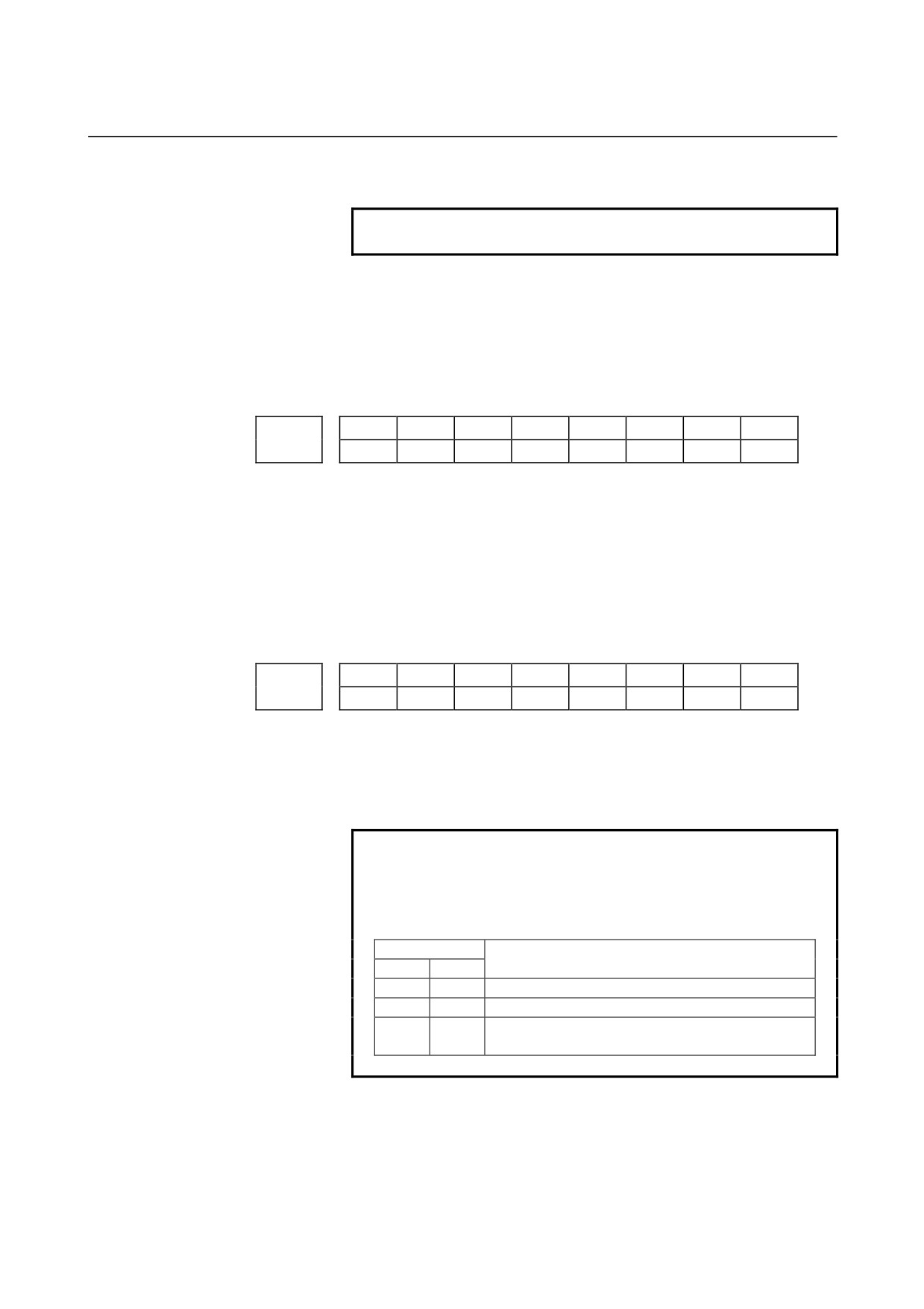
1: Bell-shaped acceleration/deceleration.
NOTE
Bit 4 (PRT) of parameter No. 1603 is invalid.
BEL
In the AI contour control mode:
0 : Linear acceleration/deceleration before look-ahead interpolation
is used.
1 : Bell-shaped
acceleration/deceleration
before
look-ahead
interpolation is used.
#7
#6
#5
#4
#3
#2
#1
#0
1604
DS2
[Data type]
Bit
DS2
When an overtravel alarm is issued for stored stroke check 2 during
linear acceleration/deceleration before interpolation, the function to
perform deceleration in advance so that the feedrate set in parameter
No. 12700 can be attained at the issuance of the alarm is:
0 : Disabled.
1 : Enabled.
#7
#6
#5
#4
#3
#2
#1
#0
JGLx
CTLx
1610
JGLx
CTBx
CTLx
[Data type]
Bit axis
CTLx
Acceleration/deceleration in cutting feed including feed in dry run
0 : Exponential acceleration/deceleration is applied.
1 : Linear acceleration/deceleration after interpolation is applied.
NOTE
To use bell-shaped acceleration/deceleration after
interpolation, set this parameter to 0 and select the
acceleration/deceleration using CTBx, bit 1 of
parameter No.1610.
Parameter
Acceleration/deceleration
CTBx
CTLx
0
0
Exponential acceleration/deceleration
0
1
Linear acceleration/deceleration after interpolation
Bell-shaped acceleration/deceleration after
1
0
interpolation
CTBx Acceleration/deceleration in cutting feed including feed in dry run
0 : Exponential acceleration/deceleration or linear acceleration/
deceleration after interpolation is applied
(depending on the
setting in CTLx, bit 0 of parameter No.1610).
- 82 -

B-64120EN/01
4.DESCRIPTION OF PARAMETERS
1 : Bell-shaped acceleration/deceleration after interpolation is
applied.
NOTE
This parameter is effective only when the function
of bell-shaped acceleration/deceleration after
interpolation in cutting feed is provided. If the
function is not provided, the setting in CTLx, bit 0 of
parameter No.1610, determines the type of
acceleration/deceleration irrespective of the setting
in this parameter.
JGLx
Acceleration/deceleration in jog feed
0 : Exponential acceleration/deceleration is applied.
1 : Linear acceleration/deceleration after interpolation or bell-shaped
acceleration/deceleration
after
interpolation
is
applied
(depending on which is used for cutting feed).
Time constant T or T1
used for linear acceleration/deceleration or
1620
bell-shaped acceleration/deceleration in rapid traverse for each axis
[Data type]
Word axis
[Unit of data]
ms
[Valid data range]
0 to 4000
Specify a time constant used for acceleration/deceleration in rapid
traverse for each axis.
(1) When bell-shaped acceleration/deceleration is set
Set time constant T1 for bell-shaped acceleration/deceleration in
this parameter, and set time constant T2 in parameter No. 1621.
(2) When linear acceleration/deceleration is set
Set time constant T for linear acceleration/deceleration in this
parameter, and set 0 in parameter No. 1621.
NOTE
1 When parameter No.1621 (time constant T2 used
for bell-shaped acceleration/deceleration in rapid
traverse) is set to 0, linear
acceleration/deceleration is applied in rapid
traverse even if the function is provided. In this
case, this parameter stands for a time constant
used in linear acceleration/deceleration in rapid
traverse.
2 Depending on the set time constant values, a
movement may be made at a feedrate a little lower
than the rapid traverse rate for a certain time
before the rapid traverse rate is attained by
acceleration. To prevent this, set the time
constants to a multiple of 8.
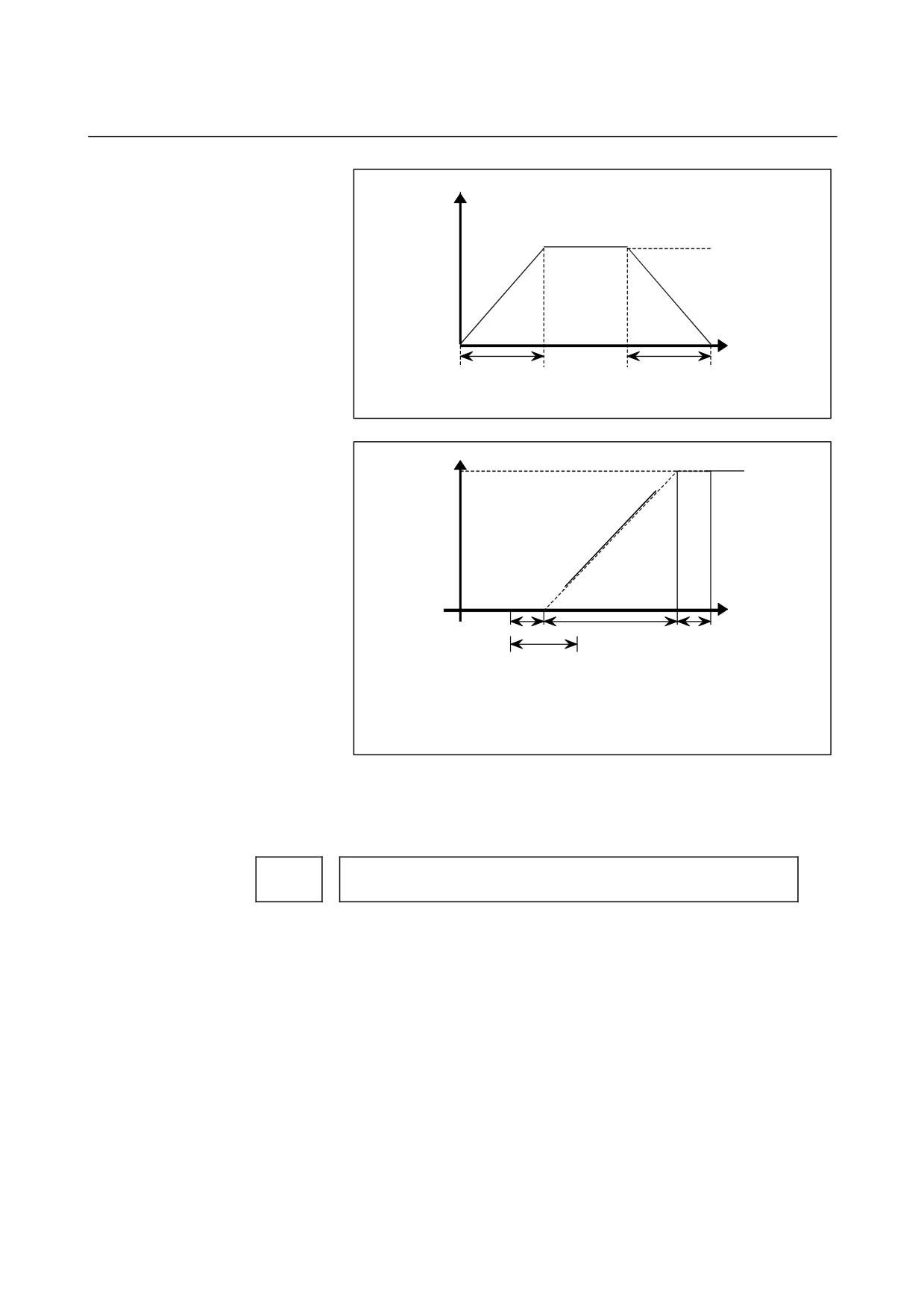
<Rapid traverse linear acceleration/deceleration>
- 83 -
4.DESCRIPTION OF PARAMETERS
B-64120EN/01
Speed
Rapid traverse
feed rate
Time
T
T
T: Time constant for linear acceleration/deceleration
<Rapid traverse bell shaped acceleration/deceleration>
Speed
Rapid
traverse rate
Time
T
2
/
T
1
T
2/2
T
2
T
1
: Set a time constant used for linear acceleration/deceleration
T
2: Set a time for rounding.
Total time=T
1
+ T
2
Time for linear=T
1 - T2
Time for rounding part=T
2
Set the value when the rapid traverse rate is 100%. If it is under 100%,
the total time is reduced. (Constant acceleration method)
The value of T1 is determined from the torque of motor. Usually set
the value of T2 to 24 ms or 32 ms.
Time constant t T2
used for bell-shaped acceleration/deceleration in rapid
1621
traverse for each axis
[Data type] Word axis
[Unit of data] ms
[Valid data range]
0 to 512
Specify time constant T2 used for bell-shaped acceleration/
deceleration in rapid traverse for each axis.
- 84 -
B-64120EN/01
4.DESCRIPTION OF PARAMETERS
NOTE
1 Set parameter No.1620 to time constant T1 used
for bell-shaped acceleration/deceleration in rapid
traverse, and set this parameter to time constant
T2.
For details of time constants T1 and T2, see the
description of parameter No.1620.
2 When this parameter is set to 0, linear acceleration/
deceleration is applied in rapid traverse. The
setting in parameter No.1620 is used as a time
constant in linear acceleration/deceleration.
Time constant of exponential acceleration/deceleration or bell-shaped
1622
acceleration/deceleration after interpolation, or linear
acceleration/deceleration after interpolation in cutting feed for each axis
[Data type]
Word axis
[Unit of data]
ms
[Valid data range]
0 to 4000 (exponential acceleration/deceleration in cutting feed)
0 to
512
(linear or bell-shaped acceleration/deceleration after
interpolation in cutting feed)
Set the time constant used for exponential acceleration/deceleration in
cutting feed, bell-shaped acceleration/deceleration after interpolation
or linear acceleration/deceleration after interpolation in cutting feed
for each axis. Except for special applications, the same time constant
must be set for all axes in this parameter. If the time constants set for
the axes differ from each other, proper straight lines and arcs cannot
be obtained.
This parameter is valid for threading, irrespective of the
acceleration/deceleration type. For threading cycles G76 and G92
(G78 in the G code system B or C), this parameter is valid for
operations other than exponential acceleration/deceleration. (T series)
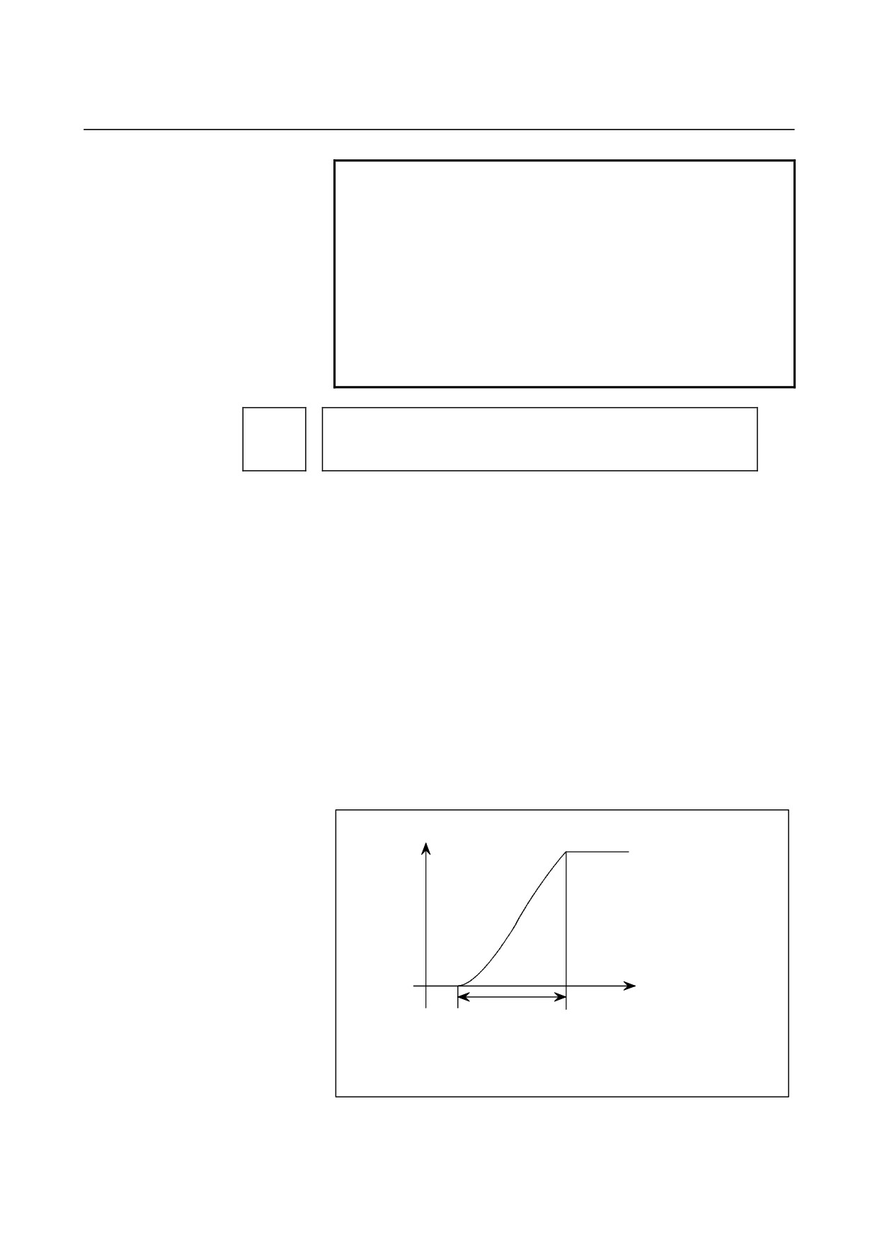
Bell-shaped acceleration/deceleration after cutting feed interpolation
Speed
Time
T
T : Total time. it is constant irrespective of feed rate.
(Time constant is constant).
The curve corresponds to that T
1
= T/2 and T
2
= T/2
set in parameter No.1620 and 1621.
- 85 -
4.DESCRIPTION OF PARAMETERS
B-64120EN/01
1623
FL rate of exponential acceleration/deceleration in cutting feed for each axis
[Data type]
Word axis
[Unit of data, valid data range]
Valid data range
Increment system
Unit of data
IS-A, IS-B
IS-C
Millimeter machine
1 mm/min
0, 6 to 15000
0, 6 to 12000
Inch machine
0.1 inch/min
0, 6 to 6000
0, 6 to 4800
Rotation axis
1 deg/min
0, 6 to 15000
0, 6 to 12000
Set the lower limit (FL rate) of exponential acceleration/deceleration
in cutting feed for each axis.
NOTE
Except for special applications, this parameter
must be set to 0 for all axes. If a value other than 0
is specified, proper straight lines and arcs cannot
be obtained.
Time constant of exponential acceleration/deceleration or bell-shaped
1624
acceleration/deceleration or linear acceleration/deceleration after
interpolation, in jog feed for each axis.
[Data type]
Word axis
[Unit of data]
ms
[Valid data range]
0 to 4000 (exponential acceleration/deceleration in jog feed)
0 to
512
(linear or bell-shaped acceleration/deceleration after
interpolation in jog feed)
Set the time constant used for exponential acceleration/deceleration,
bell-shaped acceleration/deceleration or linear acceleration/
deceleration after interpolation in jog feed for each axis. The type to
select depends on the settings of the parameters CTLx, CTBx, and
JGLx (Nos. 1610#0, #1, and #4).
1625
FL rate of exponential acceleration/deceleration in jog feed for each axis.
[Data type]
Word axis
[Unit of data, valid data range]
Valid data range
Increment system
Unit of data
IS-A, IS-B
IS-C
Millimeter machine
1 mm/min
6 to 15000
6 to 12000
Inch machine
0.1 inch/min
6 to 6000
6 to 4800
Rotation axis
1 deg/min
6 to 15000
6 to 12000
Set the lower limit (FL rate) of exponential acceleration/deceleration
in cutting feed for each axis.
Time constant of exponential acceleration/deceleration in the thread cutting
1626
cycle for each axis
- 86 -

B-64120EN/01
4.DESCRIPTION OF PARAMETERS
[Data type] Word axis
[Unit of data] ms
[Valid data range]
0 to 4000
Set the time constant used for exponential acceleration/deceleration in
the thread cutting cycle (G76, G78 (G92 in G code system A)) for
each axis.
If the acceleration type is not exponential acceleration/deceleration,
parameter No. 1622 becomes valid.
FL rate of exponential acceleration /deceleration in the thread cutting cycle
1627
for each axis
[Data type] Word axis
[Unit of data, valid data range]
Valid data range
Increment system
Unit of data
IS-A, IS-B
IS-C
Millimeter machine
1 mm/min
6 to 15000
6 to 12000
Inch machine
0.1 inch/min
6 to 6000
6 to 4800
Set the lower limit (FL rate) of exponential acceleration/deceleration
in the thread cutting cycle (G76, G78 (G92 in G code system A)) for
each axis.
- 87 -
4.DESCRIPTION OF PARAMETERS
B-64120EN/01
Minimum deceleration ratio (MDR) of the inner circular cutting rate in
1710
automatic corner override
[Data type] Byte
[Unit of data]
%
[Valid data range]
1 to 100
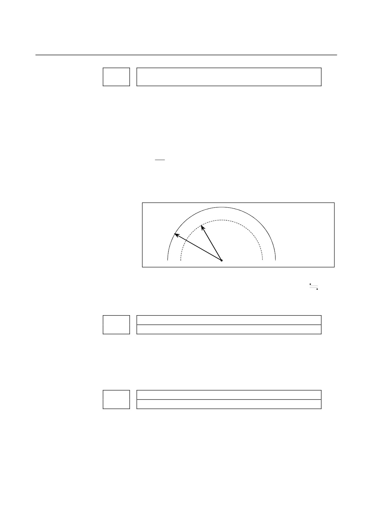
This parameter sets the minimum deceleration ratio (MDR) when the
inner circular cutting speed is changed by automatic corner override.
In circular cutting with an inward offset, the actual feedrate
for a specified feedrate (F) is expressed as follows:
Rc
F×
Rp
Rc: Radius of the path of the cutter's center.
Rp: Programmed radius
Then, the actual feedrate is controlled so that the feedrate on the
programmed path can achieve the specified feedrate F.
Rc
Path of the
Programmed path
cutter's center
Rp
Fig. 4.17 (a) Rp and Rc
If Rc is too small in comparison with Rp, such that Rc/Rp
0, the
cutter will stop. To prevent this, a minimum deceleration ratio (MDR)
is set.
1711
Angle (θp) used to recognize an inner corner in inner corner override
[Data type]
Byte
[Unit of data]
Degree
[Valid data range]
1 to 179 (standard value = 91)
This parameter sets the angle used to recognize an inner corner for
inner corner override by automatic corner override.
1712
Amount of override for an inner corner
[Data type]
Byte
[Unit of data]
%
[Valid data range]
1 to 100 (standard value = 50)
Set the amount of override for an inner corner.
- 88 -
B-64120EN/01
4.DESCRIPTION OF PARAMETERS
1713
Distance Le from the starting point in inner corner override
[Data type]
2-word
[Unit of data]
Increment system
IS-A
IS-B
IS-C
Unit
Millimeter input
1
0.1
0.01
mm
Inch input
0.1
0.01
0.001
inch
[Valid data range]
0 to 3999
Set distance Le from the starting point in an inner comer for corner
override.
1714
Distance Ls up to the ending point in inner corner override
[Data type]
2-word
[Unit of data]
Increment system
IS-A
IS-B
IS-C
Unit
Millimeter input
1
0.1
0.01
mm
Inch input
0.1
0.01
0.001
inch
[Valid data range]
0 to 3999
Set distance Ls up to the end point in an inner corner for corner
override.
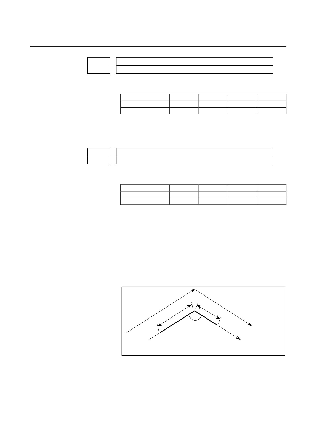
If θ ≤ θp, the inside of a comer is recognized. (θp is set in parameter
1711.)
When an inner corner is recognized, the feedrate is overridden in the
range of Le in the block immediately before the intersection of the
corner and Ls in the next block following the intersection.
Ls and Le are each a straight line connecting the intersection of the
corner and a given point on the path of the cutter's center.
Ls and Le are set in parameters 1713 and 1714.
Ls
Le
θ
b
Programmed
a
path
Cutter center path
An override is applied from point a to b.
Fig.4.17 (b) Distance Le and Ls in the automatic corner override at an
inner corner
- 89 -
4.DESCRIPTION OF PARAMETERS
B-64120EN/01
1722
Rapid traverse feedrate reduction ratio for overlapping rapid traverse blocks
[Data type]
Byte axis
[Unit of data]
%
[Valid data range]
1 to 100
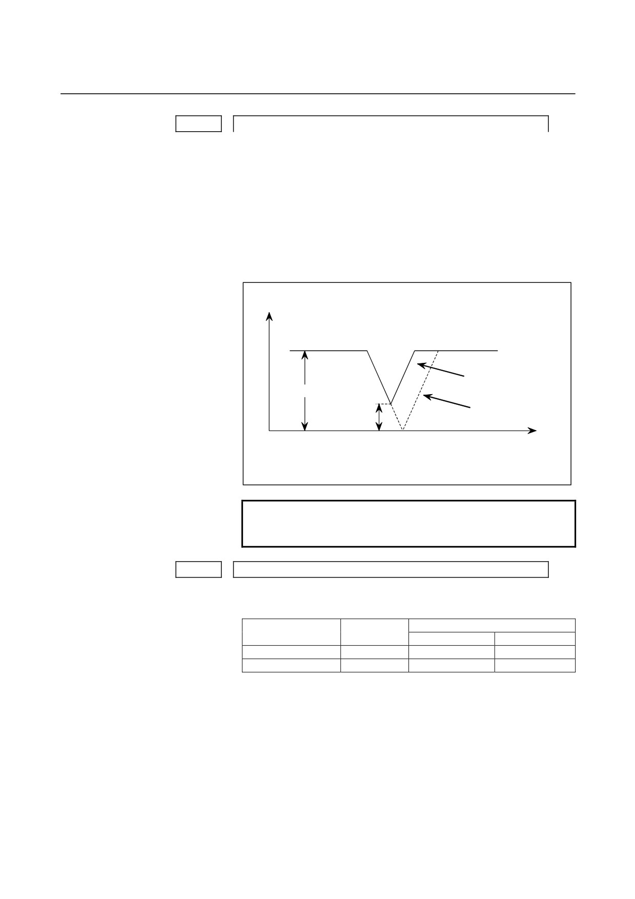
This parameter is used when rapid traverse blocks are arranged
successively, or when a rapid traverse block is followed by a block
that does not cause, movement. When the feedrate for each axis of a
block is reduced to the ratio set in this parameter, the execution of the
next block is started.
Examples
X-axis feedrate
N1 G00 X- - ;
N2 G00 X- - ;
When the function of
overlapping rapid traverse
blocks is enabled
Fh
When the function of
overlapping rapid traverse
blocks is disabled
Fd
t
Fh
: Rapid traverse feedrate
α
: Setting of parameter No.1722 (feedrate reduction ratio)
Fd : Feedrate where deceleration is terminated: Fh × α/100
NOTE
The parameter No.1722 is effective when
parameter No.1601 #4 (RT0) is set to 1.
1730
Maximum feedrate for arc radius R
[Data type]
Word
[Unit of data, valid data range]
Valid data range
Increment system
Unit of data
IS-A, IS-B
IS-C
Millimeter machine
1 mm/min
8 to 15000
8 to 12000
Inch machine
0.1 inch/min
8 to 6000
8 to 4800
Set a maximum feedrate for the arc radius set in parameter No.1731.
- 90 -
B-64120EN/01
4.DESCRIPTION OF PARAMETERS
1731
Arc radius value corresponding to a maximum feedrate
[Data type]
2-word
[Unit of data]
Increment system
IS-A
IS-B
IS-C
Unit
Linear axis (millimeter machine)
0.01
0.001
0.0001
mm
Linear axis (inch machine)
0.001
0.0001
0.00001
inch
[Valid data range]
1000 to 99999999
Set the arc radius corresponding to the maximum feedrate set in
parameter No.1730.
1732
Minimum value (RV min) for arc radius-based feedrate clamp
[Data type]
Word
[Unit of data, valid data range]
Valid data range
Increment system
Unit of data
IS-A, IS-B
IS-C
Millimeter machine
1 mm/min
0 to 15000
0 to 12000
Inch machine
0.1 inch/min
0 to 6000
0 to 4800
The arc radius-based feedrate clamping function reduces the
maximum feedrate as the arc radius decreases. When the specified
maximum feedrate is not greater than RV min (minimum value for arc
radius-based feedrate clamping), RV min is used as the maximum
feedrate.
1740
Critical angle subtended by two blocks for automatic corner deceleration
[Data type]
2-word
[Unit of data]
0.001 deg
[Valid data range]
0 to 180000
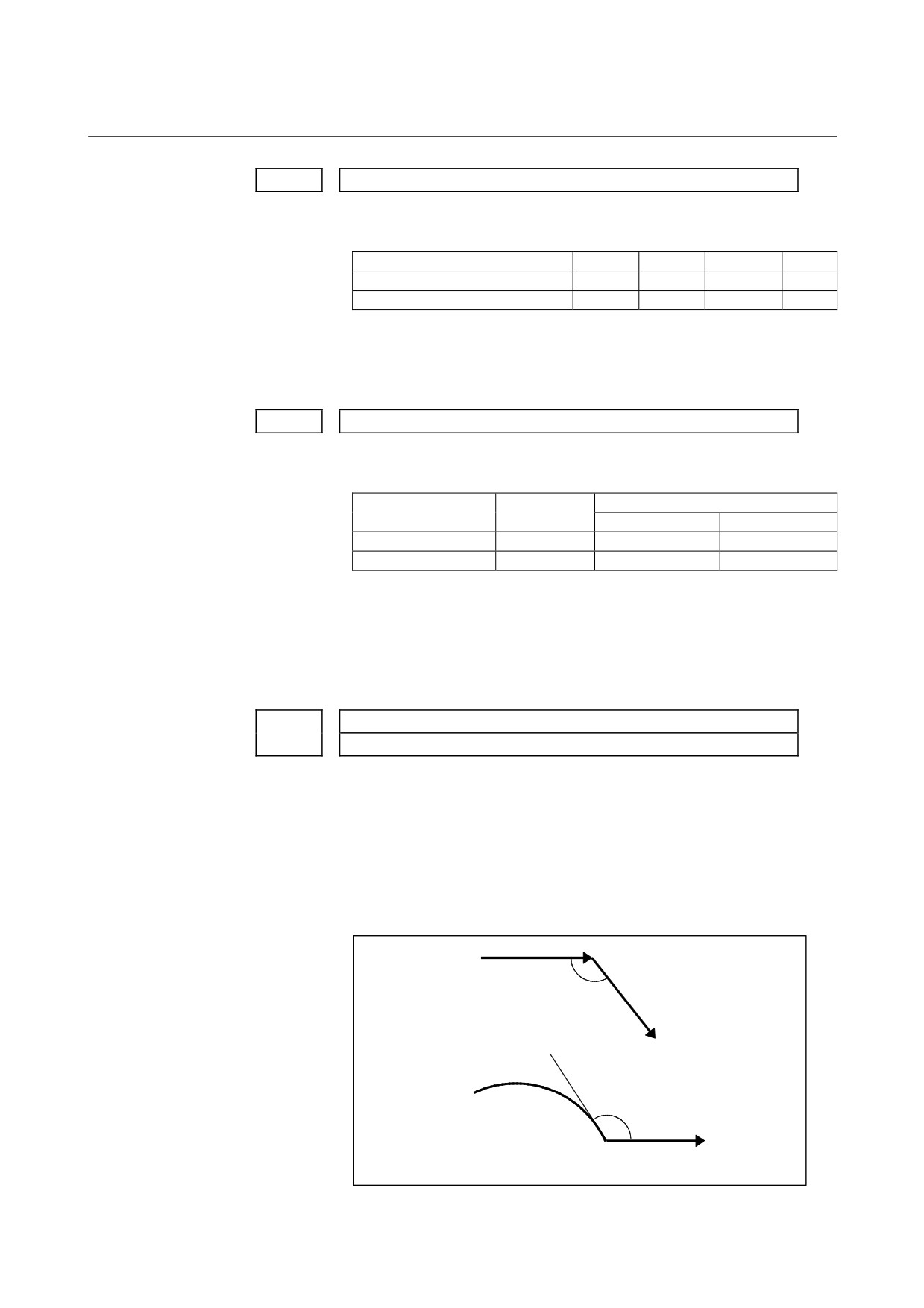
Set a critical angle to be subtended by two blocks for corner
deceleration when the angle-based automatic corner deceleration
function is used.
The angle subtended by two blocks is defined as q in the examples
shown below.
Block A (G01)
Block B (G01)
θ
Angle subtended by two straight lines
θ
Block A (G02)
Block B(G01)
Angle subtended by an arc and its tangent
- 91 -
4.DESCRIPTION OF PARAMETERS
B-64120EN/01
1741
Feedrate for assuming the termination of automatic corner deceleration
(for acceleration/deceleration after interpolation)
[Data type]
Word axis
[Unit of data, valid data range]
Valid data range
Increment system
Unit of data
IS-A, IS-B
IS-C
Millimeter machine
1 mm/min
6 to 15000
6 to 12000
Inch machine
0.1 inch/min
6 to 6000
6 to 4800
Rotation axis
1 deg/min
6 to 15000
6 to 12000
Set the feedrate for assuming the termination of deceleration in
automatic corner deceleration.
Exponential acceleration/deceleration time constant for cutting feed in the
1762
advanced preview control mode
[Data type]
Word axis
[Unit of data]
ms
[Valid data range]
0 to 4000
Set an exponential acceleration/deceleration time constant for cutting
feed in the advanced preview control mode.
Minimum speed in exponential acceleration/deceleration for cutting feed in
1763
the advanced preview control mode
[Data type]
Word axis
[Unit of data, valid data range]
Valid data range
Increment system
Unit of data
IS-A, IS-B
IS-C
Millimeter machine
1 mm/min
6 to 15000
6 to 12000
Inch machine
0.1 inch/min
6 to 6000
6 to 4800
Rotation axis
1 deg/min
6 to 15000
6 to 12000
Set minimum speed (FL) in exponential acceleration/deceleration for
cutting feed in the advanced preview control mode.
- 92 -
B-64120EN/01
4.DESCRIPTION OF PARAMETERS
Time constant of linear acceleration/deceleration or bell-shaped
acceleration/deceleration after interpolation in cutting feed in advanced
1768
preview control, AI advanced preview control, or AI contour control mode
[Data type]
Word
[Unit of data]
msec
[Valid data range]
Advanced preview control, AI advanced preview control
0, 8 to 512
AI contour control
0, 4 to 256
Set the time constant to be used for linear or bell-shaped
acceleration/deceleration after interpolation in cutting feed in
advanced preview control, AI advanced preview control, or AI
contour control mode.
NOTE
For bell-shaped acceleration/deceleration, the
function of bell-shaped acceleration/deceleration
after cutting feed interpolation is required.
Time constant of linear acceleration/deceleration or bell-shaped
acceleration/deceleration after interpolation in cutting feed for each axis in
1769
advanced preview control, AI advanced preview control, or AI contour
control mode
[Data type]
Word axis
[Unit of data]
msec
[Valid data range]
Advanced preview control, AI advanced prevoew control
0, 8 to 512
AI contour control
0, 4 to 256
Set the time constant to be used for linear or bell-shaped
acceleration/deceleration after interpolation in cutting feed in
advanced preview control, AI advanced preview control, or AI
contour control mode for each axis. Which acceleration/deceleration
type, the linear or bell-shaped type, is to be used is specified by bit 3
(BS2) and bit 6 (LS2) of parameter No. 1602.
NOTE
1 If 0 is set in parameter No. 1769 for all axes, the
value set in parameter No. 1768 is used. For other
than special purposes, set a time constant in
parameter No. 1768, which is common to all axes.
2 If a different time constant is set in parameter No.
1769, a correct straight line or arc shape cannot be
obtained.
Parameter 1 for setting the acceleration rate of linear
acceleration/deceleration before interpolation in advanced preview control,
AI advanced preview control, or AI contour control mode (maximum
1770
machining speed during linear acceleration/deceleration before
interpolation)
- 93 -
4.DESCRIPTION OF PARAMETERS
B-64120EN/01
[Data type]
2-word
[Unit of data, valid data range]
Valid data range
Increment system
Unit of data
IS-A, IS-B
IS-C
Millimeter machine
1 mm/min
6 to 240000
6 to 100000
Inch machine
0.1 inch/min
6 to 96000
6 to 48000
This parameter is used to set the acceleration rate of linear
acceleration/deceleration before interpolation in advanced preview
control, AI advanced preview control, or AI contour control mode. In
this parameter, set the maximum machining speed during linear
acceleration/deceleration before interpolation. Set the time used to
reach the maximum machining speed in parameter No.1771.
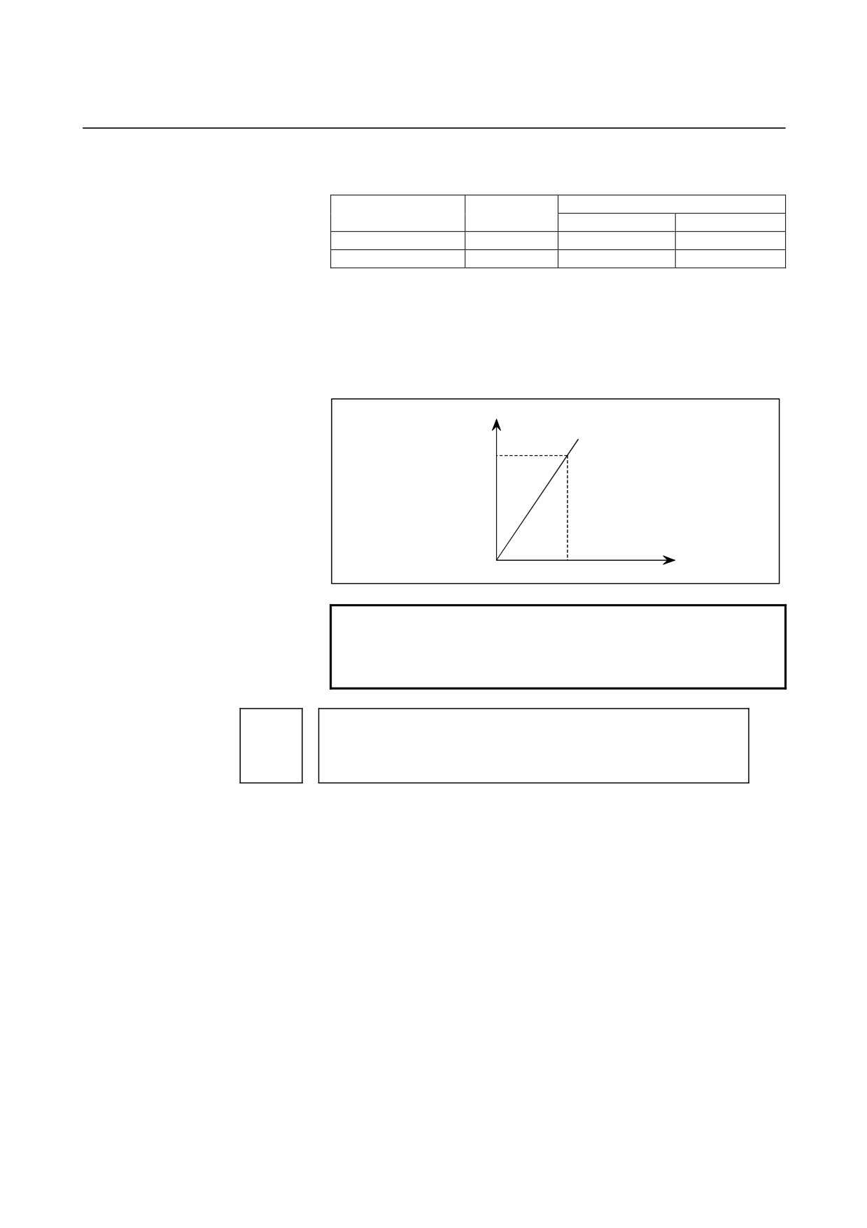
Speed
Parameter 1
(No.1770)
Time
Parameter 2 (No.1771)
NOTE
When 0 is set in parameter No.1770 or parameter
No.1771, linear acceleration/deceleration before
interpolation is disabled.
Parameter 2 for setting the acceleration rate of linear
acceleration/deceleration before interpolation in advanced preview control,
1771
AI advanced preview control, or AI contour control mode (time until the
maximum machining speed is reached during linear
acceleration/deceleration before interpolation)
[Data type] Word
[Unit of data] msec
[Valid range]
0 to 4000
This parameter is used to set the acceleration rate of linear
acceleration/deceleration before interpolation in advanced preview
control, AI advanced preview control, or AI contour control mode. In
this parameter, set the maximum machining speed during linear
acceleration/deceleration before interpolation. In this parameter, set
the time (time constant) used to reach the speed set in parameter
No.1770.
- 94 -
B-64120EN/01
4.DESCRIPTION OF PARAMETERS
NOTE
1 When 0 is set in parameter No.1770 or parameter
No.1771, linear acceleration/deceleration before
interpolation is disabled.
2 In parameter Nos. 1770 and 1771, set values that
satisfy the following:
Parameter No.1770/Parameter No.1771 ≥ 5
3 If 0 is set in parameter No. 1770 or 1771 in AI
advanced preview control or AI contour control, P/S
alarm 5157 is issued.
Time constant for bell-shaped acceleration/deceleration of acceleration time
1772
fixed type before look-ahead interpolation
[Data type]
Byte
[Unit of data]
msec
[Valid data range]
0 to 255
This parameter is used to set a time constant when the BEL parameter
(bit
7 of parameter No.1603) is set to 1, that is, when bell-shaped
acceleration/deceleration before look-ahead interpolation is selected in
AI contour control mode. Set the value of tb as shown below. When 0
is set, linear acceleration/deceleration before interpolation is applied.
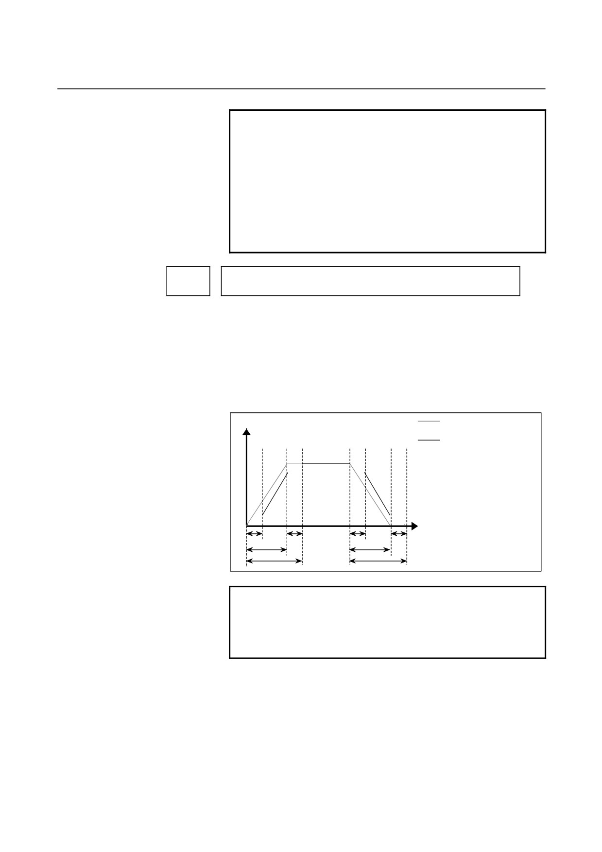
Feedrate
Linear
acceleration/deceleration
Bell-shaped
acceleration/deceleration
ta: Depends on linear acceleration.
tb: Bell-shaped time constant
tc: Bell-shaped
acceleration/deceleration
tc=ta+tb
Time
tb
tb
tb
tb
ta
ta
tc
tc
NOTE
The option for bell-shaped
acceleration/deceleration before look-ahead
interpolation is required. This parameter is enabled
only in AI contour control mode.
- 95 -
4.DESCRIPTION OF PARAMETERS
B-64120EN/01
Time constant T of rapid traverse linear acceleration/deceleration for each
1773
axis or time constant T1 of rapid traverse bell-shaped
acceleration/deceleration for each axis in AI contour control mode
[Data type]
Word axis
[Unit of data]
msec
[Valid data range]
0 to 4000
Set the time constant of rapid traverse acceleration/deceleration in AI
contour control mode.
(1) When bit 6 (RBL) of parameter No. 1603 is set to 1 (when
bell-shaped acceleration/deceleration is set)
Set time constant T1 of bell-shaped acceleration/deceleration in
this parameter, and set time constant T2 in parameter No. 1774.
(2) When bit 6 (RBL) of parameter No. 1603 is set to 0 (when linear
acceleration/deceleration is set)
Set time constant T of linear acceleration/deceleration in this
parameter, and set 0 in parameter No. 1774.
For an axis for which 0 is set in this parameter, the value set in
parameter No. 1620 is used.
NOTE
In advanced preview control and AI advanced
preview control modes, parameter No. 1773 cannot
be used.
1774
Time constant T2 of rapid traverse bell-shaped acceleration/deceleration for
each axis in AI contour control mode
[Data type] Word axis
[Unit of data] msec
[Valid data range]
0 to 512
For each axis, set time constant T2 of rapid traverse bell-shaped
acceleration/deceleration in AI contour control mode. For an axis for
which 0 is set in this parameter, the value set in parameter No. 1621 is
used.
- 96 -

B-64120EN/01
4.DESCRIPTION OF PARAMETERS
NOTE
1 In advanced preview control and AI advanced
preview control modes, parameter No. 1774
cannot be used.
2 To perform bell-shaped acceleration/deceleration,
set the following parameter:
AI advanced preview control and AI contour
control: Bit 6 (RBL) of parameter No. 1603 = 1
3 When acceleration/deceleration before
interpolation is set for rapid traverse, linear
interpolation type positioning is performed.
When the following parameters are set,
acceleration/deceleration before interpolation is
performed:
AI advanced preview control and AI contour
control: Bit 1 (AIR) of parameter No. 7054 = 0
Alternatively, bit 1 (LRP) of parameter No. 1401 =
1 and bit 1 (AIR) of parameter No.7054 = 1
1775
(Must not be used)*(Always set 0.)
1776
(Must not be used)*(Always set 0.)
Minimum speed for the automatic corner deceleration function (for advanced
1777
preview control, AI advanced preview control, or AI contour control)
[Data type] Word
[Unit of data, valid data range]
Valid data range
Increment system
Unit of data
IS-A, IS-B
IS-C
Millimeter machine
1 mm/min
6 to 15000
6 to 12000
Inch machine
0.1 inch/min
6 to 6000
6 to 4800
Set a speed at which the number of buffered pulses in deceleration is
assumed to be
0 when linear acceleration/deceleration before
interpolation is used.
Critical angle subtended by two blocks for automatic corner deceleration (for
1779
advanced preview control, AI advanced preview control, or AI contour
control)
[Data type]
2-word
[Unit of data]
0.001 deg
[Valid data range]
0 to 180000
Set a critical angle to be subtended by two blocks for corner
deceleration when the angle-based automatic corner deceleration
function is used.
The angle subtended by two blocks is defined as q in the examples
shown below.
- 97 -
4.DESCRIPTION OF PARAMETERS
B-64120EN/01
Block A (G01)
Block B (G01)
θ
Angle subtended by two straight lines
θ
Block A (G02)
Block B (G01)
Angle subtended by an arc and its tangent
Allowable speed difference for the speed difference-based corner
1780
deceleration function (for linear acceleration/deceleration before
interpolation)
[Data type] Word
[Unit of data, valid data range]
Valid data range
Increment system
Unit of data
IS-A, IS-B
IS-C
Millimeter machine
1 mm/min
6 to 15000
6 to 12000
Inch machine
0.1 inch/min
6 to 6000
6 to 4800
Set the speed difference for the speed difference-based automatic
corner deceleration function when linear acceleration/deceleration
before interpolation is used.
1781
Allowable speed difference for the speed difference-based corner
deceleration function (linear acceleration/deceleration after interpolation)
[Data type] Word axis
[Unit of data, valid data range]
Valid data range
Increment system
Unit of data
IS-A, IS-B
IS-C
Millimeter machine
1 mm/min
6 to 15000
6 to 12000
Inch machine
0.1 inch/min
6 to 6000
6 to 4800
Rotation axis
1 deg/min
6 to 15000
6 to 12000
Set speed difference for the speed difference-based automatic corner
deceleration function when linear acceleration/deceleration after
interpolation used.
- 98 -
B-64120EN/01
4.DESCRIPTION OF PARAMETERS
Allowable speed difference for the speed difference based corner
1783
deceleration function (linear acceleration/deceleration before interpolation)
[Data type] Word axis
[Unit of data, valid data range]
Valid data range
Increment system
Unit of data
IS-A, IS-B
IS-C
Millimeter machine
1 mm/min
6 to 15000
6 to 12000
Inch machine
0.1 inch/min
6 to 6000
6 to 4800
Rotation axis
1 deg/min
6 to 15000
6 to 12000
A separate allowable feedrate difference can be set for each axis. The
allowable feedrate difference is set for each axis with this parameter.
Among the axes that exceed the specified allowable feedrate
difference, the axis with the greatest ratio of the actual feedrate
difference to the allowable feedrate difference is used as the reference
to calculate the reduced feedrate at the corner.
Speed when overtravel alarm has generated during acceleration/deceleration
1784
before interpolation
[Data type]
Word
[Unit of data, valid data range]
Valid data range
Increment system
Unit of data
IS-A, IS-B
IS-C
Millimeter machine
1 mm/min
6 to 15000
6 to 12000
Inch machine
0.1 inch/min
6 to 6000
6 to 4800
Rotation axis
1 deg/min
6 to 15000
6 to 12000
Deceleration is started beforehand to reach the feedrate set in the
parameter when an overtravel alarm is issued (when a limit is reached)
during linear acceleration/deceleration before interpolation.
By
using this parameter, the overrun distance that occurs when an
overtravel alarm is output can be reduced.
This setting can be applied also to rapid traverse blocks by setting bit
0 (OTR) of parameter No.7057.
(M series)
NOTE
1 When 0 is set in this parameter, the control
described above is not exercised.
2 Use type-B linear acceleration/deceleration before
interpolation (by setting bit 0 (FWB) of parameter
No.1602 to 1).
3 The control described above is applicable only to
stored stroke check 1.
4 The control described above is performed for the
axes specified in the current block and next block.
By setting bit 5 (ODA) of parameter No. 7055, the
control can be performed just for the axis specified
in the current block.
- 99 -
4.DESCRIPTION OF PARAMETERS
B-64120EN/01
Parameter for determining an allowable acceleration when the feedrate is set
1785
by acceleration
[Data type] Word axis
[Unit of data] ms
[Valid data range]
0 to 32767
This parameter sets the time required to attain the maximum cutting
feedrate to determine the allowable acceleration when the feedrate is
determined by acceleration in AI advanced preview control mode or
AI contour control mode.
The maximum cutting feedrate and the data set in this parameter are
used to determine the allowable acceleration. As the maximum
cutting feedrate parameter, parameter No.1432
(maximum cutting
feedrate in AI advanced preview control mode or AI contour control
mode) is used.
Speed (mm/min)
Allowable
acceleration
Parameter (No.1432)
Time (msec)
Parameter (No.1785)
Time (time constant) until the maximum machining speed is reached during
linear acceleration/deceleration before interpolation in advanced preview
1786
control, AI advanced preview control, or AI contour control mode
(for rotation axes)
[Data type]
Word
[Unit of data]
msec
[Valid data range]
0 to 4000
This parameter is used to set the acceleration rate (for rotation axes) of
linear acceleration/deceleration before interpolation in advanced
preview control, AI advanced preview control, or AI contour control
mode.
This parameter sets the time (time constant) required to reach the
speed set in parameter No. 1770. The acceleration rate set by this
parameter applies to commands containing rotation axes.
(The
acceleration rate set by parameter No. 1771 applies to commands not
containing rotation axes.)
NOTE
If 0 is set in this parameter, the acceleration rate
set in parameter No. 1771 applies also to
commands containing rotation axes.
- 100 -

B-64120EN/01
4.DESCRIPTION OF PARAMETERS
Time constant of bell-shaped acceleration/deceleration of acceleration time
1787
fixed type before look-ahead interpolation in the AI advanced preview control
or AI contour control mode
(for rotation axes)
[Data type] Byte
[Unit of data] msec
[Valid data range]
0 to 255
This parameter sets the time constant
(for rotation axes) when
bell-shaped acceleration/deceleration before look-ahead interpolation
is selected as the acceleration/deceleration applied in AI advanced
preview control or AI contour control mode.
The time constant set in this parameter applies to commands
containing rotation axes.
(The time constant set in parameter No.
1772 applies to commands not containing rotation axes.)
NOTE
1 The option for bell-shaped
acceleration/deceleration before look-ahead
interpolation is required.
2 This parameter is valid only when a non-zero value
is set in parameter No. 1786.
- 101 -

4.DESCRIPTION OF PARAMETERS
B-64120EN/01
4.15
PARAMETERS OF SERVO (1 OF 2)
#7
#6
#5
#4
#3
#2
#1
#0
1800
RBK
FFR
OZR
CVR
[Data type]
Bit
CVR
When velocity control ready signal VRDY is set ON before position
control ready signal PRDY comes ON
0: A servo alarm is generated.
1: A servo alarm is not generated.
OZR
When manual reference position return is attempted in the halt state
during automatic operation (feed hold stop state) under any of the
conditions listed below:
0: Manual reference position return is not performed, with P/S
alarm No.091.
1: Manual reference position return is performed without an alarm
occurring.
<Conditions>
(1) When there is a remaining distance to travel.
(2) When an auxiliary function
(miscellaneous function,
spindle-speed function, tool function) is being executed.
(3) When a cycle such as a dwell cycle or canned cycle is being
executed.
FFR
Feed-forward control is enabled for
0 : Cutting feed only
1 : Cutting feed and rapid traverse
RBK
Backlash compensation applied separately for cutting feed and rapid
traverse
0: Not performed
1: Performed
#7
#6
#5
#4
#3
#2
#1
#0
CIN
CCI
PM2
PM1
1801
CIN
CCI
[Data type]
Bit
PM1, PM2
Sets a gear ratio between the spindle and motor when the servo
motor-based speed control function is used.
Magnification
PM2
PM1
1/1
0
0
Magnification=
1/2
0
1
spindle speed / motor speed
1/4
1
0
1/8
1
1
CCI
The in-position area for cutting feed is:
0 : Set in parameter No.1826 (same as for rapid traverse).
1 : Set in bit 5 (CIN) of parameter No.1801.
- 102 -
B-64120EN/01
4.DESCRIPTION OF PARAMETERS
CIN
When bit 4 (CCI) of parameter No.1801 = 1, the in-position area for
cutting feed is:
0 : Use value in parameter No.1827 if the next block is also for
cutting feed, or use value in parameter No.1826 if the next block
is not for cutting feed.
1 : Use value in parameter No.1827, regardless of the next block.
(The setting of parameter No.1826 is used for rapid traverse, and
the setting of parameter No.1827 is used for cutting feed.)
#7
#6
#5
#4
#3
#2
#1
#0
DPS
B15
DC2
DC4
CTS
1802
FWC
B15
DC2
DC4
NOTE
After this parameter is set, the power needs to be
turned off.
[Data type]
Bit
CTS
The servo motor-based speed control function is:
0 : Not used
1 : Used
DC4
The reference position on an encoder (linear scale or rotary encoder)
with absolute address reference marks is established as follows:
0 : An absolute position is established by detecting three reference
marks.
1 : An absolute position is established by detecting four reference
marks.
NOTE
With an encoder with the absolute address zero
point (linear scale or rotary encoder) (detection
circuit C), the setting of this parameter is invalid.
DC2
The reference position on the linear scale with absolute address
reference mark is established:
0: As determined by bit 1 (DC4) of parameter No. 1802.
1: By establishing the absolute position through detection of two
reference marks.
- 103 -
4.DESCRIPTION OF PARAMETERS
B-64120EN/01
NOTE
1 When this parameter is set to 1, set the direction of
the zero point of the encoder with bit 4 (SCPx) of
parameter No. 1817.
2 When a rotary encoder with absolute address
reference marks is used (bit 3 (DCRx) of parameter
No. 1815 = 1), this parameter becomes invalid.
Even if this parameter is set to 1, the setting of the
DC4 parameter is followed.
3 With an encoder with the absolute address zero
point (linear scale or rotary encoder) (detection
circuit C), the setting of this parameter is invalid.
B15
In backlash compensation, the travel direction is determined:
0: Without consideration of the compensation amount (pitch error,
external machine coordinate shift, etc.).
1: In consideration of the compensation amount. (FS15 format)
DPS
When servo motor-based speed control is applied, a position coder is:
0 : Used
1 : Not used
FWC
The processing of command multiplication (CMR) is performed:
0: After acceleration/deceleration after interpolation.
1: Before acceleration/deceleration after interpolation.
#7
#6
#5
#4
#3
#2
#1
#0
1803
TQF
TQA
TQI
[Data type]
Bit
TQI
While torque restriction is applied, in-position check is:
0 : Performed.
1 : Not performed.
TQA
While torque restriction is applied, checking for an excessive error in
the stopped state/during movement is:
0 : Performed.
1 : Not performed.
TQF
When torque control is performed by an axis control command of the
PMC axis control function, follow-up operation is:
0 : Not performed.
1 : Performed.
#7
#6
#5
#4
#3
#2
#1
#0
1804
SAK
ANA
IVO
[Data type]
Bit axis
IVO
When an attempt is made to release an emergency stop while the
VRDY OFF alarm ignore signal is 1:
0 : The emergency stop state is not released until the VRDY OFF
alarm ignore signal is set to 0.
1 : The emergency stop state is released.
- 104 -
B-64120EN/01
4.DESCRIPTION OF PARAMETERS
NOTE
When a reset is issued while the VRDY OFF alarm
ignore signal is set to 1 and the motor activating
current is low, the reset state can also be released,
provided this parameter is set to 1.
ANA
When an abnormal load is detected for an axis:
0 : Movement along all axes is stopped, and a servo alarm is output.
1 : No servo alarm is output, and movement along only the axes of
the group containing the axis with the abnormal load is stopped
in interlock mode. (The group number of each axis is set in
parameter No.1881.)
SAK
When the VRDY OFF alarm ignore signal IGNVRY is 1, or when the
VRDY OFF alarm ignore signals IGVRY1 to IGVRY8 are 1:
0 : Servo ready signal SA is set to 0.
1 : Servo ready signal SA remains set to 1.
#7
#6
#5
#4
#3
#2
#1
#0
1805
TQU
[Data type]
Bit
TQU
If follow-up is not performed by the torque control command of PMC
axis control, the servo error counter is:
0: Updated.
1: Not updated.
NOTE
1 This parameter is valid if follow-up is not performed
(bit 4 (TQF) of parameter No. 1803 is set to 0).
2 When torque control is switched to position control,
a reference position return must be made.
#7
#6
#5
#4
#3
#2
#1
#0
1807
SWP
[Data type]
Bit
SWP
When the αi servo amplifier is placed in the warning state (for a cause
such as a stopped fan):
0 : An alarm is issued.
Automatic operation enters the feed hold state, and the servo axis
decelerates and stops.
1 : No alarm is issued.
Automatic operation continues. When the amplifier state changes
from the warning state to alarm state, servo activation stops.
- 105 -

4.DESCRIPTION OF PARAMETERS
B-64120EN/01
#7
#6
#5
#4
#3
#2
#1
#0
NRTx
APCx
APZx
DCRx
DCLx
OPTx
1815
NRTx
APCx
APZx
DCRx
DCLx
OPTx
RVSx
NOTE
When this parameter has been set, the power must
be turned off before operation is continued.
[Data type]
Bit axis
RVSx
When rotation axis B type is set for an axis for which a scale not
having speed data is used:
0 : The NC does not maintain speed data.
1 : The NC maintains speed data.
NOTE
1 For axes that are of rotation axis B type and have a
movable range of one turn or more, use of a scale
having speed data is recommended.
2 This parameter is valid only for axes of rotation axis
B type.
3 The NC maintains speed data observed
immediately before power-off and uses the data to
obtain coordinates at the next power-on. Therefore,
if an axis turns 180 degrees or more while the
power is off, the coordinate value may be displaced
by one turn or more.
4 When you have changed this parameter, establish
the reference position again.
OPTx
Position detector
0 : A separate Pulsecoder is not used.
1 : A separate Pulsecoder is used.
For an absolute-position system using Inductosyn, set this
parameter to 1.
DCLx
As a separate position detector:
0 : Neither an encoder with absolute address reference marks (linear
scale or rotary encoder) nor encoder with the absolute address
zero point (linear scale or rotary encoder) (detection circuit C) is
used.
1 : An encoder with absolute address reference marks (linear scale
or rotary encoder) or encoder with the absolute address zero
point (linear scale or rotary encoder) (detection circuit C) is used.
- 106 -

B-64120EN/01
4.DESCRIPTION OF PARAMETERS
NOTE
When an encoder with absolute address reference
marks (linear scale or rotary encoder) or encoder
with the absolute address zero point (linear scale
or rotary encoder) (detection circuit C) (closed loop
system) is used, set bit 1 (OPTx) of parameter No.
1815 to 1. When a linear scale with the absolute
address zero point (detection circuit C) (linear
motor system) is used, however, set OPTx to 0.
DCRx
As an encoder with absolute address reference marks:
0 : A linear scale with absolute address reference marks is used.
1 : A rotary encoder with absolute address reference marks is used.
NOTE
1 Set bit 2 (DCLx) of parameter No. 1815 to 1.
2 When a rotary encoder with the absolute address
zero point (detection circuit C) is used, set this
parameter to 0.
APZx
Machine position and position on absolute position detector when the
absolute position detector is used
0 : Not corresponding
1 : Corresponding
NOTE
When an absolute position detector is used, after
primary adjustment is performed or after the
absolute position detector is replaced, this
parameter must be set to 0, power must be turned
off and on, then manual reference position return
must be performed. This completes the positional
correspondence between the machine position and
the position on the absolute position detector, and
sets this parameter to 1 automatically.
APCx
Position detector
0 : Other than absolute position detector
1 : Absolute position detector (absolute Pulsecoder)
For an absolute-position system using Inductosyn, set this
parameter to 1.
NRTx
When the machine coordinate value on a rotation axis passes the
0-degree point or a point at which the machine coordinate value is
rounded off (360 degrees or the setting of parameter No. 1260):
0 : The zero point (parameter Nos. 1860 and 1861) is updated.
1 : The zero point (parameter Nos. 1860 and 1861) is not updated.
When a scale not maintaining speed data is used, set this parameter to
1.
- 107 -
4.DESCRIPTION OF PARAMETERS
B-64120EN/01
NOTE
1 This parameter is valid only for axes of rotation axis
A type.
2 For axes of rotation axis A type that use a scale
having no speed data, be sure to set this
parameter.
3 When you have changed this parameter, establish
the reference position again.
#7
#6
#5
#4
#3
#2
#1
#0
TANx
SCPx
1817
TANx
SCPx
SCRx
NOTE
When this parameter has been set, the power must
be turned off before operation is continued.
[Data type]
Bit axis
SCRx
When rotation axis B type is set for an axis for which a scale not
having speed data is used, scale data conversion is:
0 : Not performed.
1 : Performed.
NOTE
1 This parameter is valid only for axes of rotation axis
B type.
2 When there is no discontinuous point in scale data
within the movable range of a rotation axis, do not
set this parameter for the axis even if the axis is of
rotation axis B type.
3 When you have changed this parameter, establish
the reference position again.
SCPx
When bit 2 (DC2) of parameter No. 1802 is set to 1, the zero point of
an encoder with absolute address reference marks (linear scale or
rotary encoder) is located:
0 : On the negative side.
(The reference position is located on the positive side when viewed
from the encoder zero point.)
1 : On the positive side.
(The reference position is located on the negative side when viewed
from the encoder zero point.)
- 108 -
B-64120EN/01
4.DESCRIPTION OF PARAMETERS
NOTE
1 If an incorrect value is set in this parameter, the
coordinate system cannot be established properly.
In this case, reverse the setting, and establish the
reference position again.
2 For an encoder with the absolute address zero
point (linear scale or rotary encoder) (detection
circuit C), the setting of this parameter is invalid.
TANx
Tandem control
0 : Not used
1 : Used
NOTE
Set this parameter to both master axis and slave
axis.
#7
#6
#5
#4
#3
#2
#1
#0
1818
SDCx
DG0x
RF2x
RFSx
[Data type]
Bit axis type
RFSx
When the reference position has not yet been established on an axis
for which an encoder with absolute address reference marks (linear
scale or rotary encoder) or encoder with the absolute address zero
point (linear scale or rotary encoder) (detection circuit C) is used, an
automatic reference position return
(G28) causes the following
behavior after the reference position is established:
0: A movement to the reference position is made.
1: A movement to the reference position is not made, but the
operation is completed.
RF2x
When the reference position has already been established on an axis
for which an encoder with absolute address reference marks (linear
scale or rotary encoder) or encoder with the absolute address zero
point (linear scale or rotary encoder) (detection circuit C) is used, an
automatic reference position return
(G28) causes the following
behavior:
0: A movement to the reference position is made.
1: A movement to the reference position is not made, but the
operation is completed.
DG0x
For an axis for which an encoder with absolute address reference
marks (linear scale or rotary encoder) is used, a reference position
return operation by a rapid traverse command or jog feed is:
0: Disabled.
1: Enabled.
SDCx
An encoder with the absolute address zero point (linear scale or rotary
encoder) (detection circuit C) is:
0 : Not used.
1 : Used.
- 109 -

4.DESCRIPTION OF PARAMETERS
B-64120EN/01
NOTE
After setting this parameter, be sure to turn off the
power. Note that P/S 0 (power-off request alarm) is
not issued.
#7
#6
#5
#4
#3
#2
#1
#0
DATx
CRFx
FUPx
1819
NAHx
DATx
CRFx
FUPx
[Data type]
Bit axis
FUPx
To perform follow-up when the servo is off is set for each axis.
0: The follow-up signal, *FLWU, determines whether follow-up is
performed or not.
When *FLWU is 0, follow-up is performed.
When *FLWU is 1, follow-up is not performed.
1: Follow-up is not performed.
NOTE
When the index table indexing function (M series)
is used, be sure to set FUPx of the 4th axis to 1.
CRFx
When servo alarm No.445
(software disconnection), No.446
(hardware disconnection), No.447 (hardware disconnection (separate
type)), or No.421 (excessive dual position feedback error) is issued:
0 : The reference position setting remains as is.
1 : The system enters the reference position undefined state.
DATx
With an encoder with absolute address reference marks (linear scale or
rotary encoder) or encoder with the absolute address zero point (linear
scale or rotary encode), automatic setting of parameter Nos. 1883 and
1884 at the time of a manual reference position return operation is:
0: Not performed.
1: Performed.
The automatic setting is performed according to the following steps:
<1> Set appropriate values in parameter Nos. 1815, 1821, and 1882.
* For an encoder with the absolute address zero point (linear
scale or rotary encoder) (detection circuit C), parameter No. 1882
need not be set.
<2> By manual operation, position the machine at the reference
position.
<3> Set this parameter to 1.
<4> Perform a manual reference position return operation. Upon
completion of the manual reference position return operation,
parameter Nos.1883 and 1884 are set, and this parameter is
automatically set to 0.
NAHx
In the advanced preview control mode, advanced feed-forward is:
0 : Used
1 : Not used
NOTE
Set 1 for a PMC-based control axis.
- 110 -
B-64120EN/01
4.DESCRIPTION OF PARAMETERS
1820
Command multiplier for each axis (CMR)
NOTE
When this parameter has been set, the power must
be turned off before operation is continued.
[Data type] Byte axis
Set a command multiplier indicating the ratio of the least
command increment to the detection unit for each axis.
Least command increment = detection unit × command multiplier
Relationship between the increment system and the least command
increment
(1) T series
Least
Least input increment
command
increment
Millimeter
0.001 mm (diameter specification)
0.0005 mm
Millimeter
input
0.001 mm (radius specification)
0.001 mm
machine
0.0001 inch (diameter specification)
0.0005 mm
Inch input
0.0001 inch (radius specification)
0.001 mm
IS-B
Millimeter
0.001 mm (diameter specification)
0.00005 inch
Inch
input
0.001 mm (radius specification)
0.0001 inch
machine
0.0001 inch (diameter specification)
0.00005 inch
Inch input
0.0001 inch (radius specification)
0.0001 inch
Rotation axis
0.001 deg
0.001 deg
Millimeter
0.0001 mm (diameter specification)
0.00005 mm
Millimeter
input
0.0001 mm (radius specification)
0.0001 mm
machine
0.00001 inch (diameter specification)
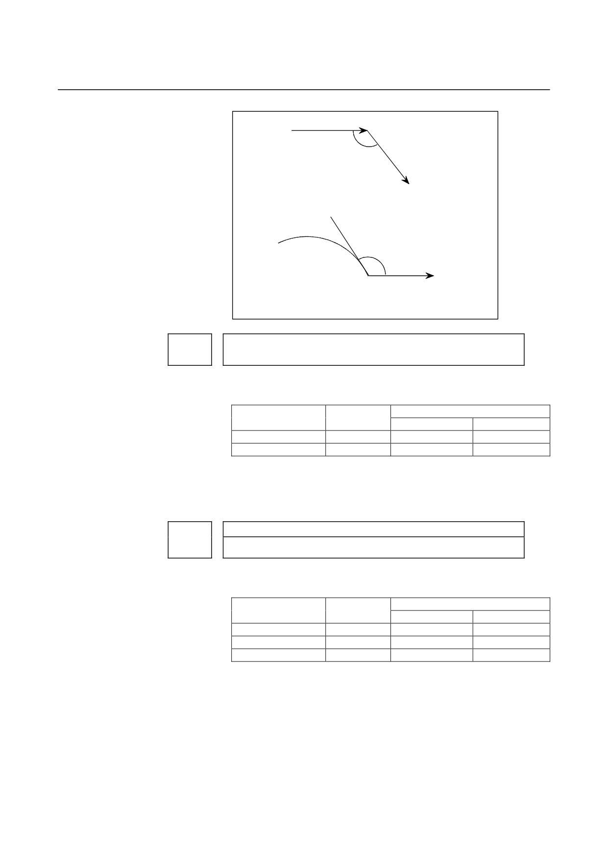
0.00005 mm
Inch input
0.00001 inch (radius specification)
0.0001 mm
IS-C
Millimeter
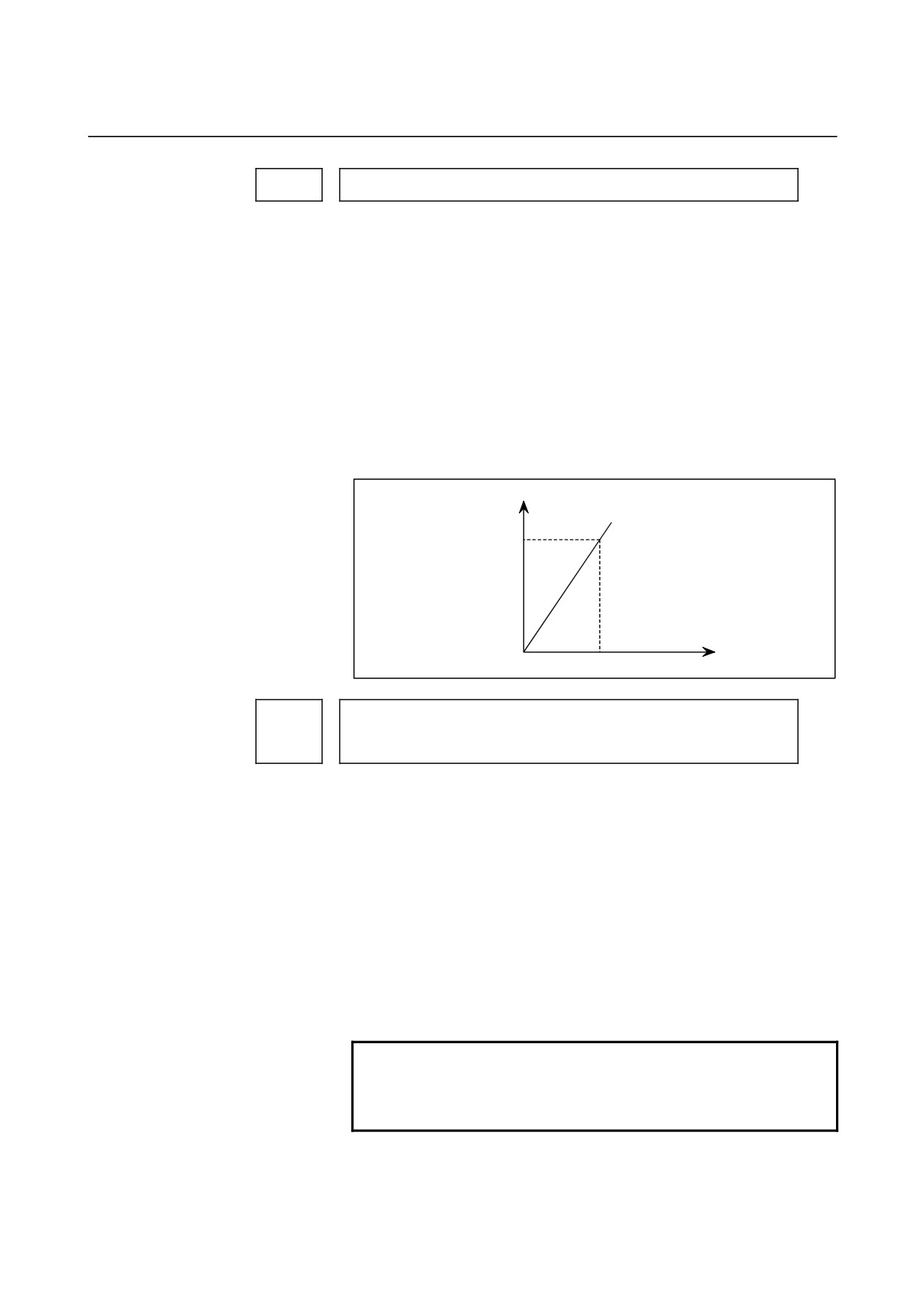
0.0001 mm (diameter specification)
0.000005 inch
Inch
input
0.0001 mm (radius specification)
0.00001 inch
machine
0.00001 inch (diameter specification)
0.000005 inch
Inch input
0.00001 inch (radius specification)
0.00001 inch
Rotation axis
0.0001 deg
0.0001 deg
(2) M series
Increment
Least input increment and least command increment
system
IS-A
IS-B
IS-C
Units
Millimeter
0.01
0.001
0.0001
mm
machine
Inch machine
0.001
0.0001
0.00001
inch
Rotation axis
0.01
0.001
0.0001
deg
Setting command multiply (CMR), detection multiply (DMR), and the
capacity of the reference counter
- 111 -