FANUC Series 0i-MODEL C, Series 0i Mate-MODEL C. PARAMETER MANUAL (B-64120EN/01) - page 3
4.DESCRIPTION OF PARAMETERS
B-64120EN/01
OTF When an overtravel alarm is issued:
0 : No signal is output.
1 : Signals are output to F124 and F126.
PLC Stroke limit check before movement is:
0: Not performed
1: Performed
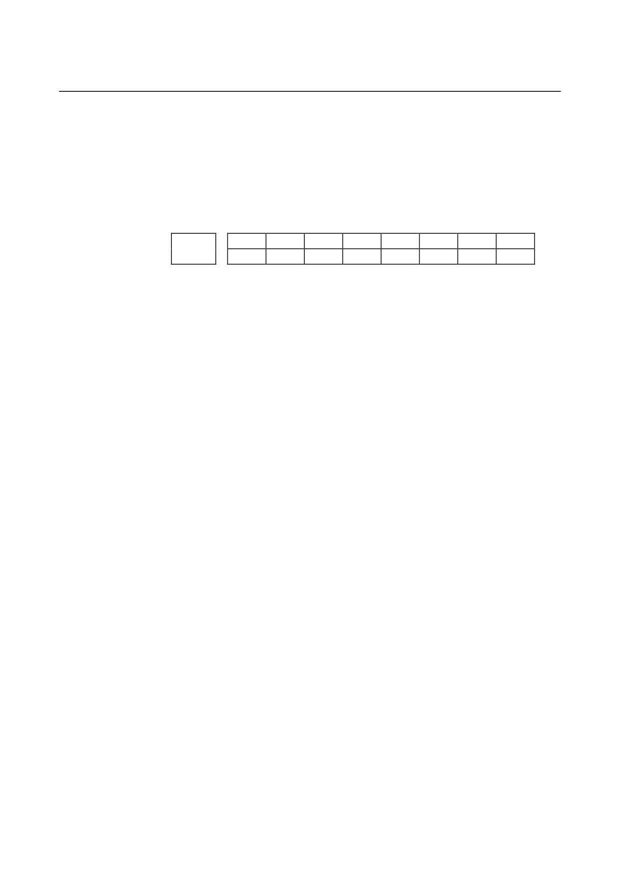
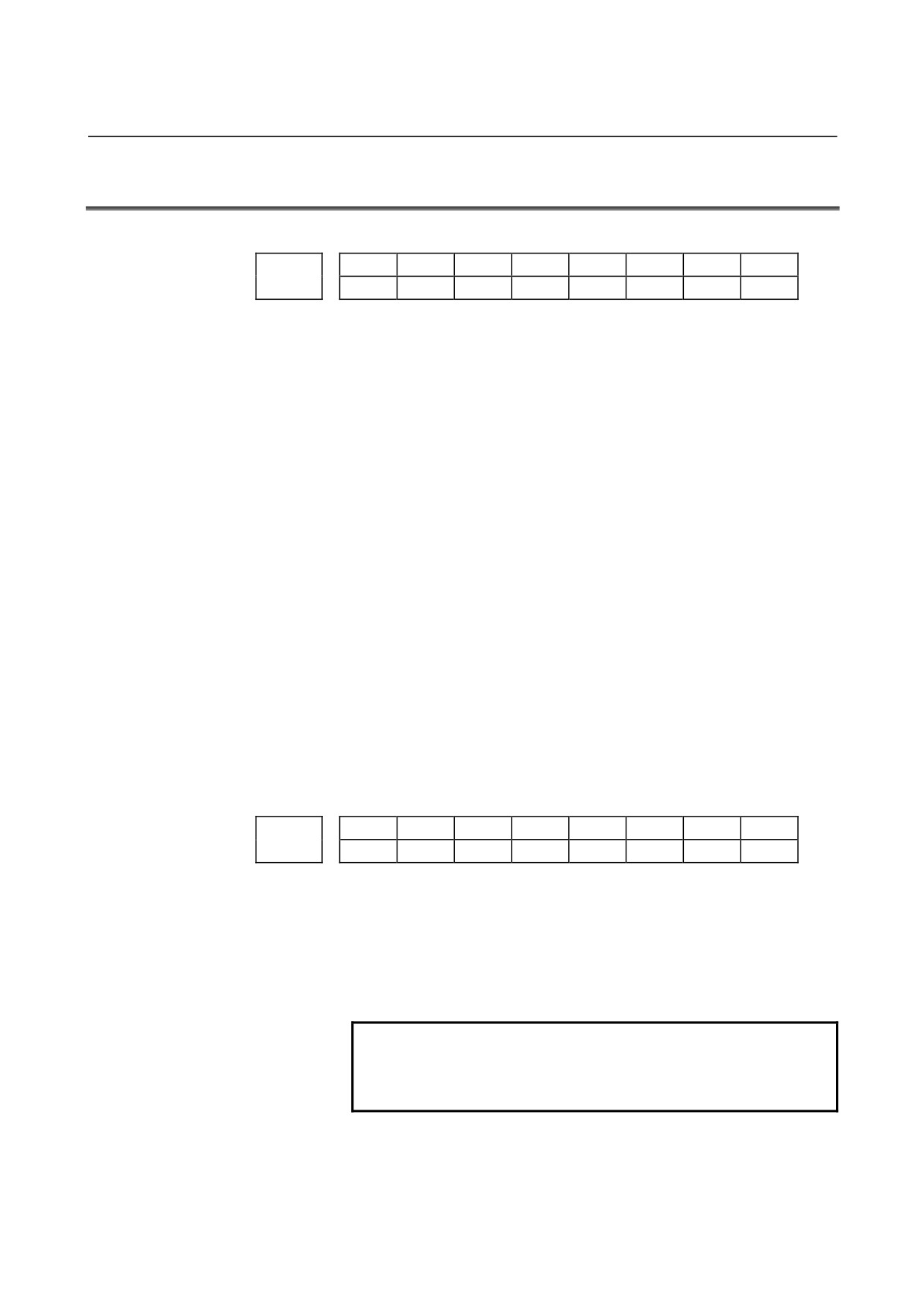
#7
#6
#5
#4
#3
#2
#1
#0
OT3x
OT2x
1310
OT2x
[Data type] Bit axis
OT2x Whether stored stroke check 2 is checked for each axis is set.
0: Stored stroke check 2 is not checked.
1: Stored stroke check 2 is checked.
OT3x Whether stored stroke check 3 is checked for each axis is set.
0: Stored stroke check 3 is not checked.
1: Stored stroke check 3 is checked.
- 52 -
B-64120EN/01
4.DESCRIPTION OF PARAMETERS
Coordinate value I of stored stroke check 1 in the positive direction on each
1320
axis
Coordinate value I of stored stroke check 1 in the negative direction on each
1321
axis
[Data type]
2-word axis
[Unit of data]
Increment system
IS-A
IS-B
IS-C
Unit
Millimeter machine
0.01
0.001
0.0001
mm
Inch machine
0.001
0.0001
0.00001
inch
Rotation axis
0.01
0.001
0.0001
deg
[Valid data range]
-99999999 to 99999999
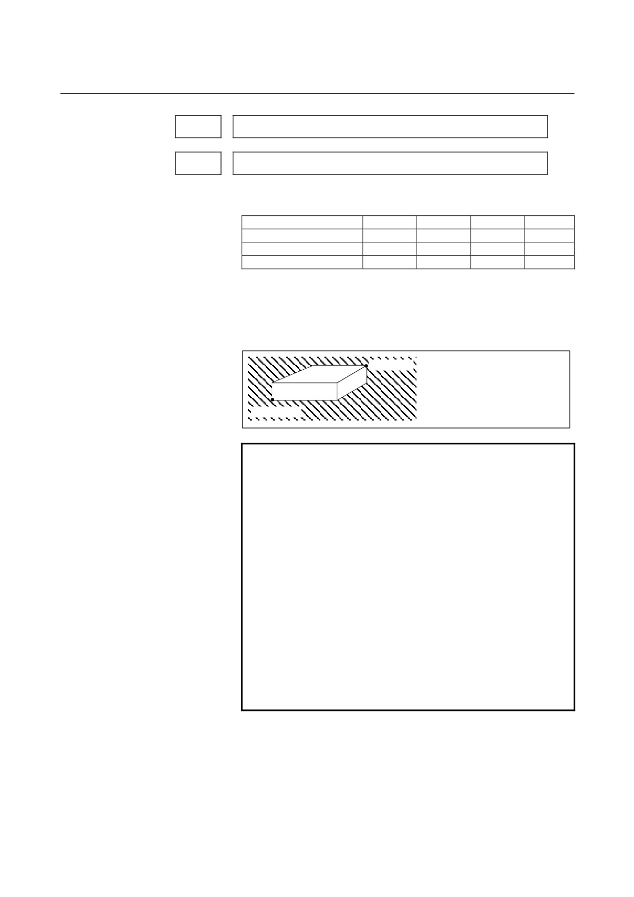
The coordinate values of stored stroke check 1 in the positive and
negative directions are set for each axis in the machine coordinate
system. The outside area of the two checks set in the parameters is
inhibited.
Set the machine coordinates of the
(Xp,Yp,Zp) boundaries in the positive direction (Xp,
Yp, and Zp) using parameter No. 1320,
and those of the boundaries in the
negative direction (Xm, Ym, and Zm)
using parameter No. 1321. The
(Xm,Ym,Zm)
prohibited area thus becomes the
hatched area in the figure on the left.
NOTE
1 For axes with diameter specification, a diameter
value must be set.
2 When the parameters are set as follows, the stroke
becomes infinite:
parameter 1320 < parameter 1321
For movement along the axis for which infinite
stroke is set, only increment commands are
available. (The stored stroke limit switching signal
also becomes invalid.) If an absolute command is
issued for this axis, the absolute register may
overflow, and normal movement will not result.
3 The prohibited area specified with these
parameters is invalid if bit 2 (LMS) of parameter
No. 1300 is set to 1 and stored stroke limit
switching signal EXLM <G007#6> is set to 1. In
such a case, the settings of parameters No. 1326
and 1327 are used, instead.
- 53 -
4.DESCRIPTION OF PARAMETERS
B-64120EN/01
Coordinate value of stored stroke check 2 in the positive direction on each
1322
axis
Coordinate value of stored stroke check 2 in the negative direction on each
1323
axis
[Data type]
2-word axis
[Unit of data]
Increment system
IS-A
IS-B
IS-C
Unit
Millimeter machine
0.01
0.001
0.0001
mm
Inch machine
0.001
0.0001
0.00001
inch
Rotation axis
0.01
0.001
0.0001
deg
[Valid data range]
-99999999 to 99999999
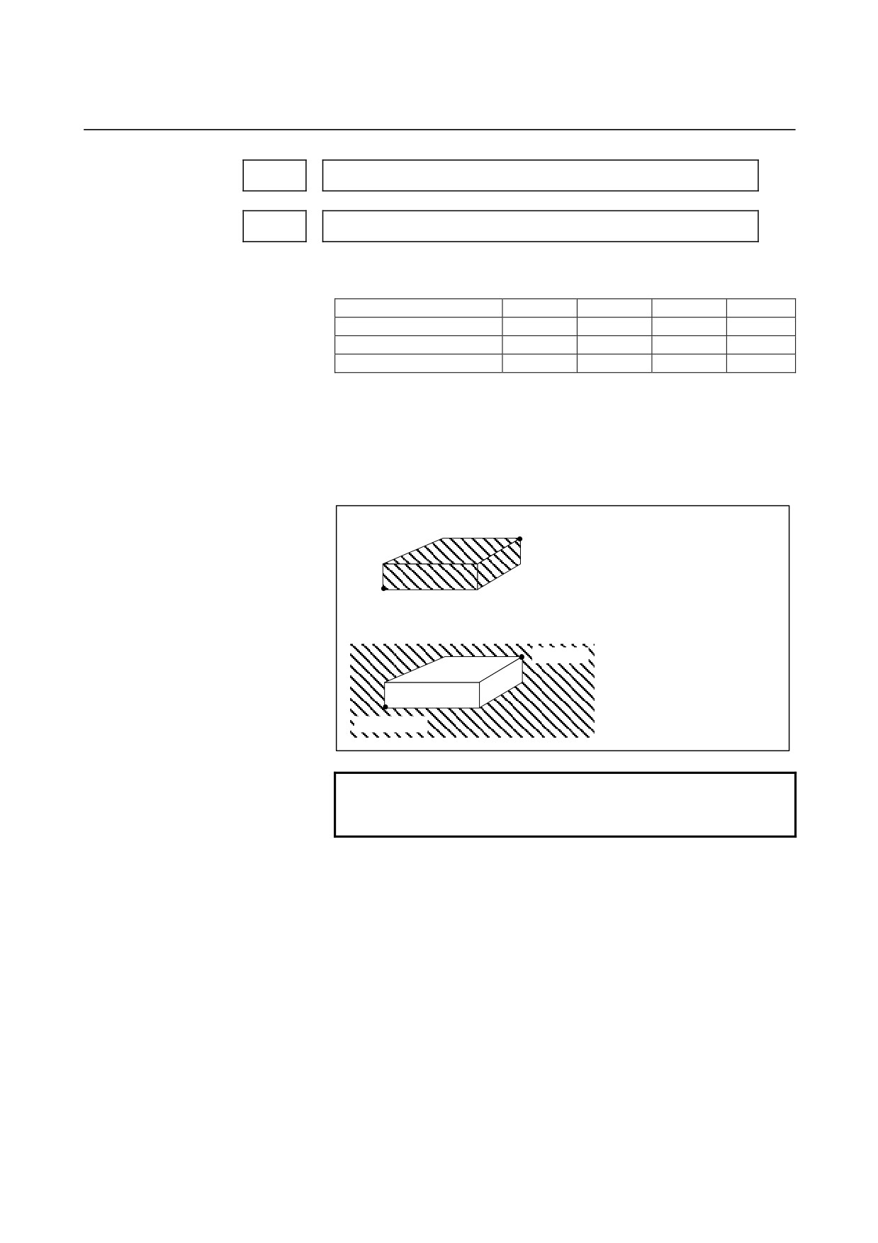
Set the coordinate values of stored stroke check 2 in the positive and
negative directions for each axis in the machine coordinate system.
OUT, #0 of parameter 1300, sets either the area outside of the area
inside specified by two checks are the inhibition area.
(1) When the prohibited area is inside the boundaries (OUT = 0)
(Xp,Yp,Zp)
Set the machine coordinates of the
boundaries in the positive direction
(Xp, Yp, and Zp) using parameter
No. 1322, and those of the
boundaries in the negative
(Xm,Ym,Zm)
direction (Xm, Ym, and Zm) using
(2) When the prohibited area is outside the parameter No. 1323. The
boundaries (OUT = 1)
prohibited area thus becomes the
(Xp,Yp,Zp)hatched area in the figure on the
left.
(Xm,Ym,Zm)
NOTE
For axes with diameter specification, a diameter
value must be set.
- 54 -
B-64120EN/01
4.DESCRIPTION OF PARAMETERS
Coordinate value of stored stroke check 3 in the positive direction on each
1324
axis
Coordinate value of stored stroke check 3 in the negative direction on each
1325
axis
[Data type]
2-word axis
[Unit of data]
Increment system
IS-A
IS-B
IS-C
Unit
Millimeter machine
0.01
0.001
0.0001
mm
Inch machine
0.001
0.0001
0.00001
inch
Rotation axis
0.01
0.001
0.0001
deg
[Valid data range]
-99999999 to 99999999
Set the coordinate values of stored stroke check 3 in the positive
and negative directions for each axis in the machine coordinate system.
The area inside the checks set in the parameter is inhibited.
NOTE
Specify diameters for any axis for which diameter
programming is specified.
Coordinate value II of stored stroke check 1 in the positive direction on each
1326
axis
Coordinate value II of stored stroke check 1 in the negative direction on each
1327
axis
[Data type]
2-word axis
[Unit of data]
Increment system
IS-A
IS-B
IS-C
Unit
Millimeter machine
0.01
0.001
0.0001
mm
Inch machine
0.001
0.0001
0.00001
inch
Rotation axis
0.01
0.001
0.0001
deg
[Valid data range]
-99999999 to 99999999
Set the coordinate values of stored stroke check 1 in the positive and
negative directions for each axis in the machine coordinate system.
The tool cannot enter the area outside the checks set in the parameter.
The inhibition area set in the parameter is enabled when bit 2 (LMS)
of parameter No. 1300 is 1 and stored stroke limit switching signal
EXLM <G007#6> is 1.
NOTE
1 Specify diameter values for any axes for which
diameter programming is specified.
2 These parameters are invalid if bit 2 (LMS) of
parameter No. 1300 is set to 0, or if stored stroke
limit switching signal EXLM <G007#6> is set to 0.
In such a case, the settings of parameters No.
1320 and 1321 are used, instead.
- 55 -
4.DESCRIPTION OF PARAMETERS
B-64120EN/01
4.12
PARAMETERS OF THE CHUCK AND TAILSTOCK
BARRIER (T SERIES)
1330
Profile of a chuck
[Data type]
Byte
[Valid data range]
0 or 1
0: Chuck which holds a workpiece on the inner surface
1: Chuck which holds a workpiece on the outer surface
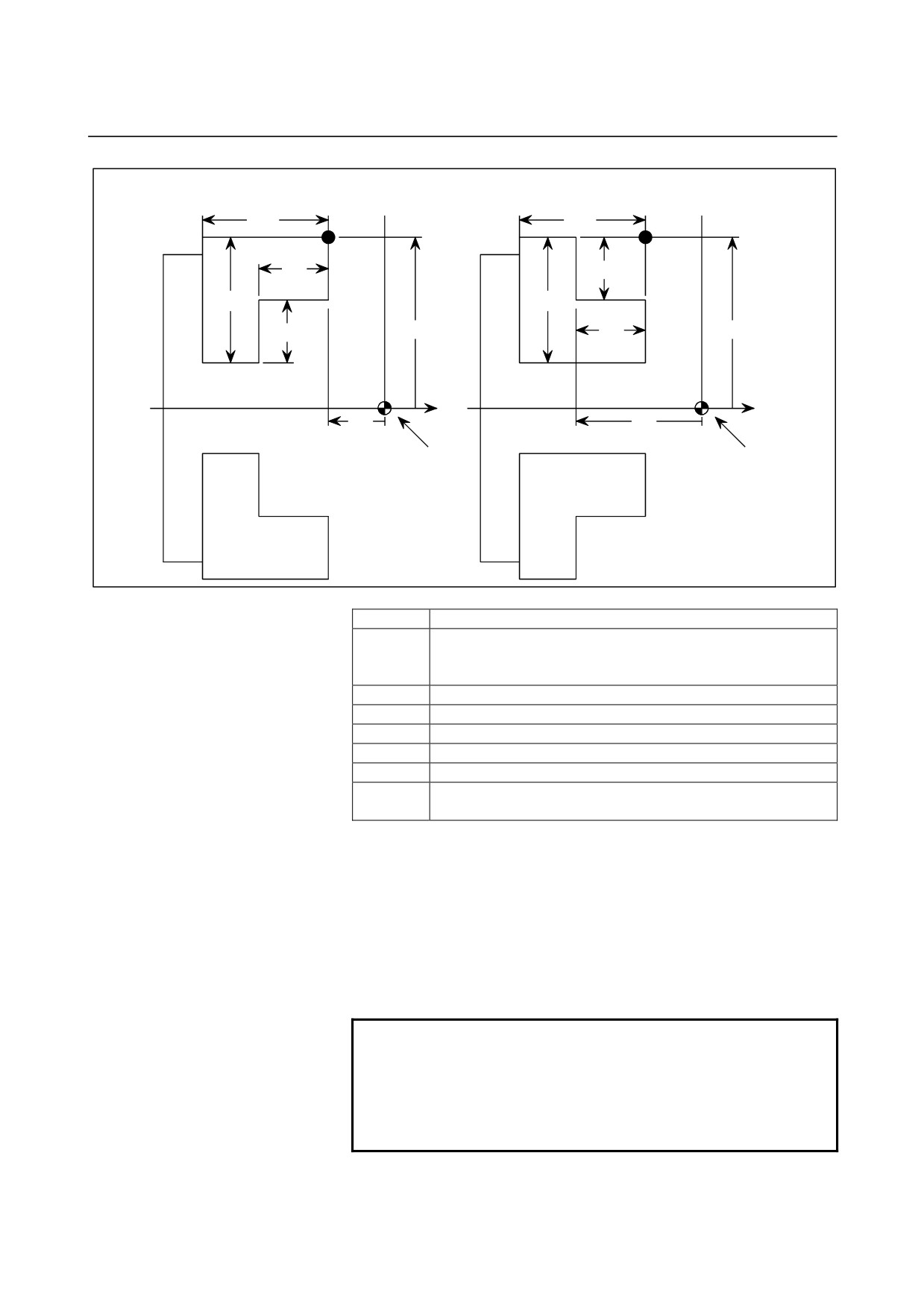
Dimensions of the claw of a chuck (L)
1331
Dimensions of the claw of a chuck (W)
1332
Dimensions of the part of a claw at which a workpiece is held (L1)
1333
Dimensions of the part of a claw at which a workpiece is held (W1)
1334
X coordinate of a chuck (CX)
1335
ZX coordinate of a chuck (CZ)
1336
[Data type]
2-word
[Unit of data]
Increment system
IS-B
IS-C
Unit
Millimeter machine
0.001
0.0001
mm
Inch machine
0.0001
0.00001
inch
[Valid range]
No.1331 to No.1334: 0 to 99999999
No.1335 to No.1336: -99999999 to 99999999
Specify the profile of a chuck.
- 56 -
B-64120EN/01
4.DESCRIPTION OF PARAMETERS
Chuck which holds a workpiece on the outer surface (TY= 1)
Chuck which holds a workpiece on the inner surface (TY= 0)
X
X
L
A
L
A
L1
W1
W
W
W1
CX
L1
CX
Z
Z
CZ
CZ
Zero point of the
Zero point of the
workpiece coordinate
workpiece coordinate
system
system
Symbol
Description
Profile of a chuck (0: Chuck which holds a workpiece on the
Ty
inner surface, 1: Chuck which holds a workpiece on the outer
surface)
CX
X coordinate of a chuck
CZ
Z coordinate of a chuck
L
Dimensions of the claw of a chuck
W
Dimensions of the claw of a chuck (radius input)
L1
Dimensions of the part of a claw at which a workpiece is held
Dimensions of the part of a claw at which a workpiece is held
W1
(radius input)
TY
Specifies the profile of a chuck. When TY is set to 0, the chuck
holding a workpiece on the inner surface is specified. When TY is set
to 1, the chuck holding a workpiece on the outer surface is specified.
The profile of the chuck is assumed to be symmetrical with respect to
the z-axis.
CX, and CZ
Specify the position (point A) of a chuck with the coordinates of the
workpiece coordinate system. In this case, do not use the coordinates
of the machine coordinate system.
NOTE
Specifying the coordinates with a diameter or
radius depends on whether the corresponding axis
conforms to diameter or radius specification. When
the axis conforms to diameter specification, specify
the coordinates with a diameter.
- 57 -
4.DESCRIPTION OF PARAMETERS
B-64120EN/01
L, L1, W and W1
Define the profile of a chuck.
NOTE
Always specify W and W1 with radiuses. Specify L
and L1 with radiuses when the Z-axis conforms to
radius specification.
Length of a tailstock (L)
1341
Diameter of a tailstock (D)
1342
Length of a tailstock (L1)
1343
Diameter of a tailstock (D1)
1344
Length of a tailstock (L2)
1345
Diameter of a tailstock (D2)
1346
Diameter of the hole of a tailstock (D3)
1347
Z coordinate of a tailstock (TZ)
1348
[Data type]
2-words
[Unit of data]
Increment system
IS-B
IS-C
Unit
Millimeter machine
0.001
0.0001
mm
Inch machine
0.0001
0.00001
inch
[Valid range]
No.1341 to No.1347: 0 to 99999999
No.1348: -99999999 to 99999999
Specify the profile of a tailstock.
- 58 -
B-64120EN/01
4.DESCRIPTION OF PARAMETERS
X
L
L
T
L
B
Workpiece
D
D
D
D
Z
Zero point of the
workpiece
coordinate system
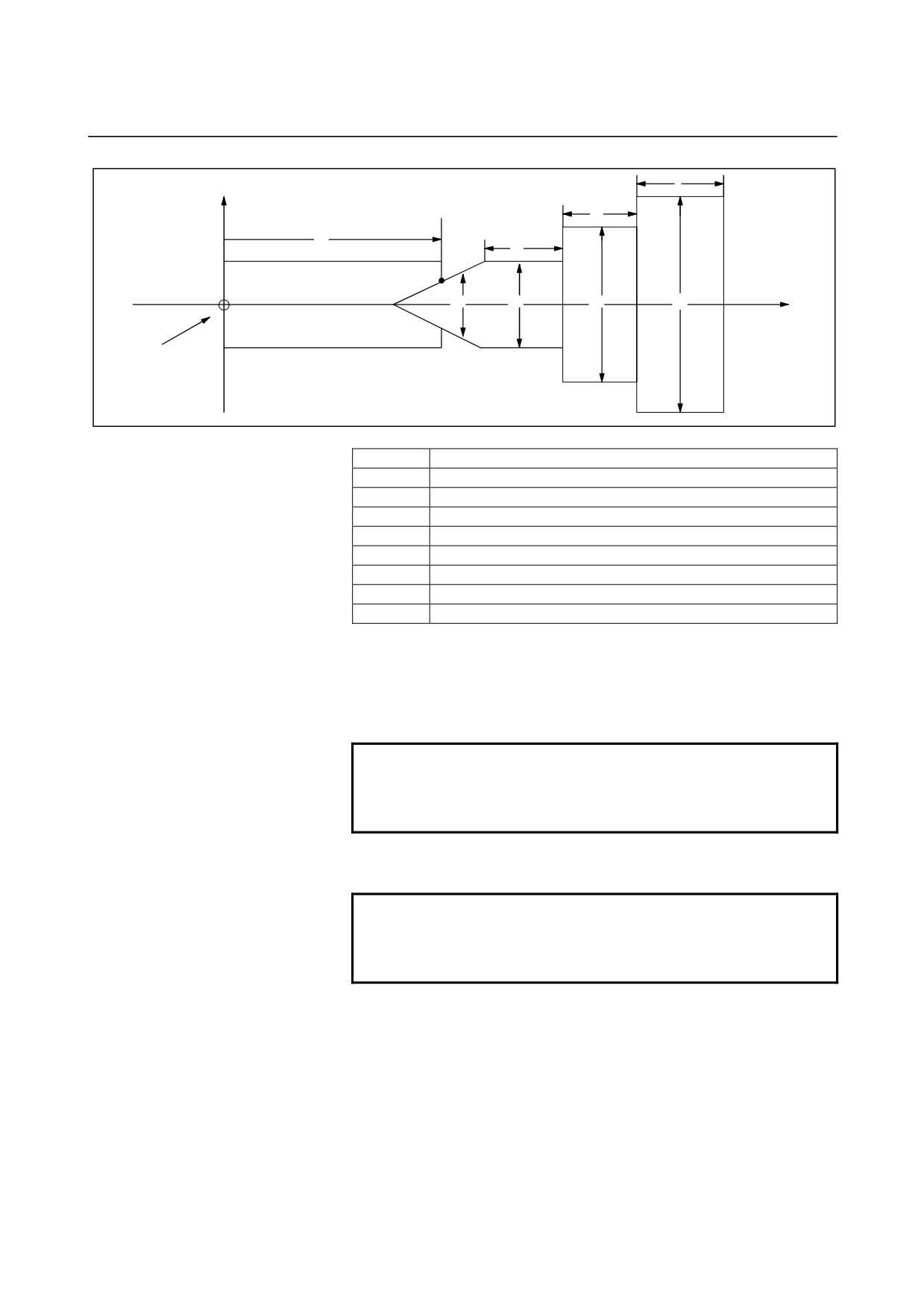
Symbol
Description
TZ
Z-axis coordinate of a tailstock
L
Length of a tailstock
D
Diameter of a tailstock (diameter input)
L1
Length of a tailstock (1)
D1
Diameter of a tailstock (1) (diameter input)
L2
Length of a tailstock (2)
D2
Diameter of a tailstock (2) (diameter input)
D3
Diameter of the hole of a tailstock (diameter input)
TZ:
Specifies the position
(point B) of a tailstock with the Z-axis
coordinate of the workpiece coordinate system. In this case, do not
use the coordinate of the machine coordinate system. The profile of
a tailstock is assumed to be symmetrical with respect to the Z-axis.
NOTE
Specifying the position of a tailstock with a radius
or diameter depends on whether the Z-axis
conforms to radius or diameter specification.
L, L1, L2, D, D1, D2, and D3
Define the profile of a tailstock.
NOTE
Always specify D, D1, D2, and D3 with diameters.
Specify L, L1, and L2 with radiuses if the Z-axis
conforms to radius specification.
- 59 -
4.DESCRIPTION OF PARAMETERS
B-64120EN/01
4.13
PARAMETERS OF FEEDRATE
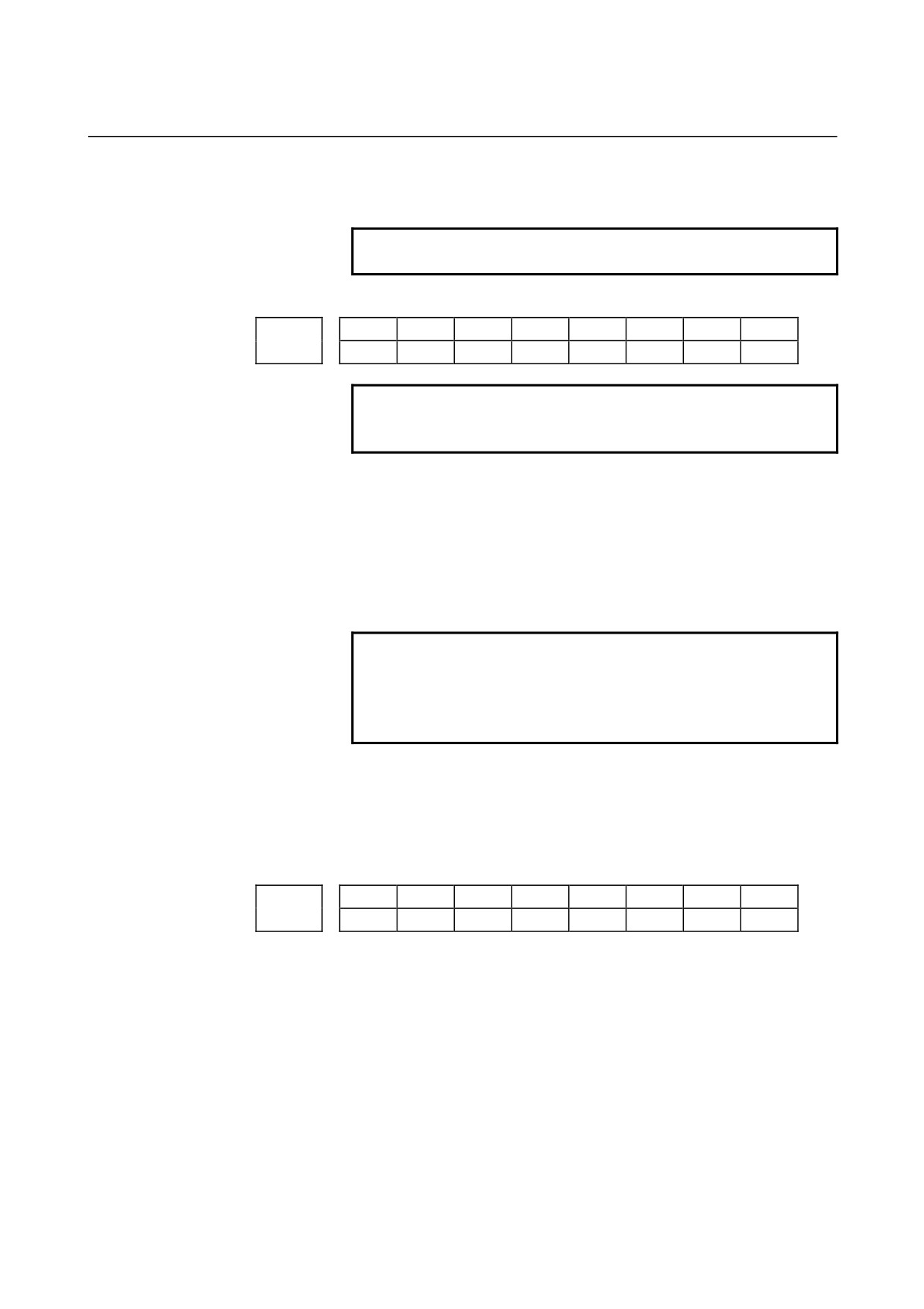
#7
#6
#5
#4
#3
#2
#1
#0
RDR
TDR
RF0
JZR
LRP
RPD
1401
RDR
TDR
RF0
LRP
RPD
[Data type]
Bit
RPD
Manual rapid traverse during the period from power-on time to the
completion of the reference position return.
0: Disabled (Jog feed is performed.)
1: Enabled
LRP
Positioning (G00)
0: Positioning is performed with non-linear type positioning so that
the tool moves along each axis independently at rapid traverse.
1: Positioning is performed with linear interpolation so that the tool
moves in a straight line.
JZR
The manual reference position return at JOG feedrate
0: Not performed
1: Performed
RF0
When cutting feedrate override is 0% during rapid traverse,
0: The machine tool does not stop moving.
1: The machine tool stops moving.
TDR
Dry run during threading or tapping (tapping cycle G74 or G84, rigid
tapping)
0: Enabled
1: Disabled
RDR
Dry run for rapid traverse command
0: Disabled
1: Enabled
#7
#6
#5
#4
#3
#2
#1
#0
JRV
JOV
NPC
1402
JOV
NPC
[Data type]
Bit
NPC
The feed per rotation command is:
0: Ineffective when a position coder is not provided.
1: Effective even when a position coder is not provided (because
the CNC converts it to the feed per minute command from F
command S command).
NOTE
To use a position coder, set this parameter to 0.
While this parameter is set to 1, threading cannot
be performed even if a position coder is provided.
JOV
Job override is:
0: Enabled
1: Disabled (tied to 100%)
JRV
Jog feed or incremental feed is
- 60 -
B-64120EN/01
4.DESCRIPTION OF PARAMETERS
0: Performed at feed per minute.
1: Performed at feed per rotation.
NOTE
Specify a feedrate in parameter No.1423.
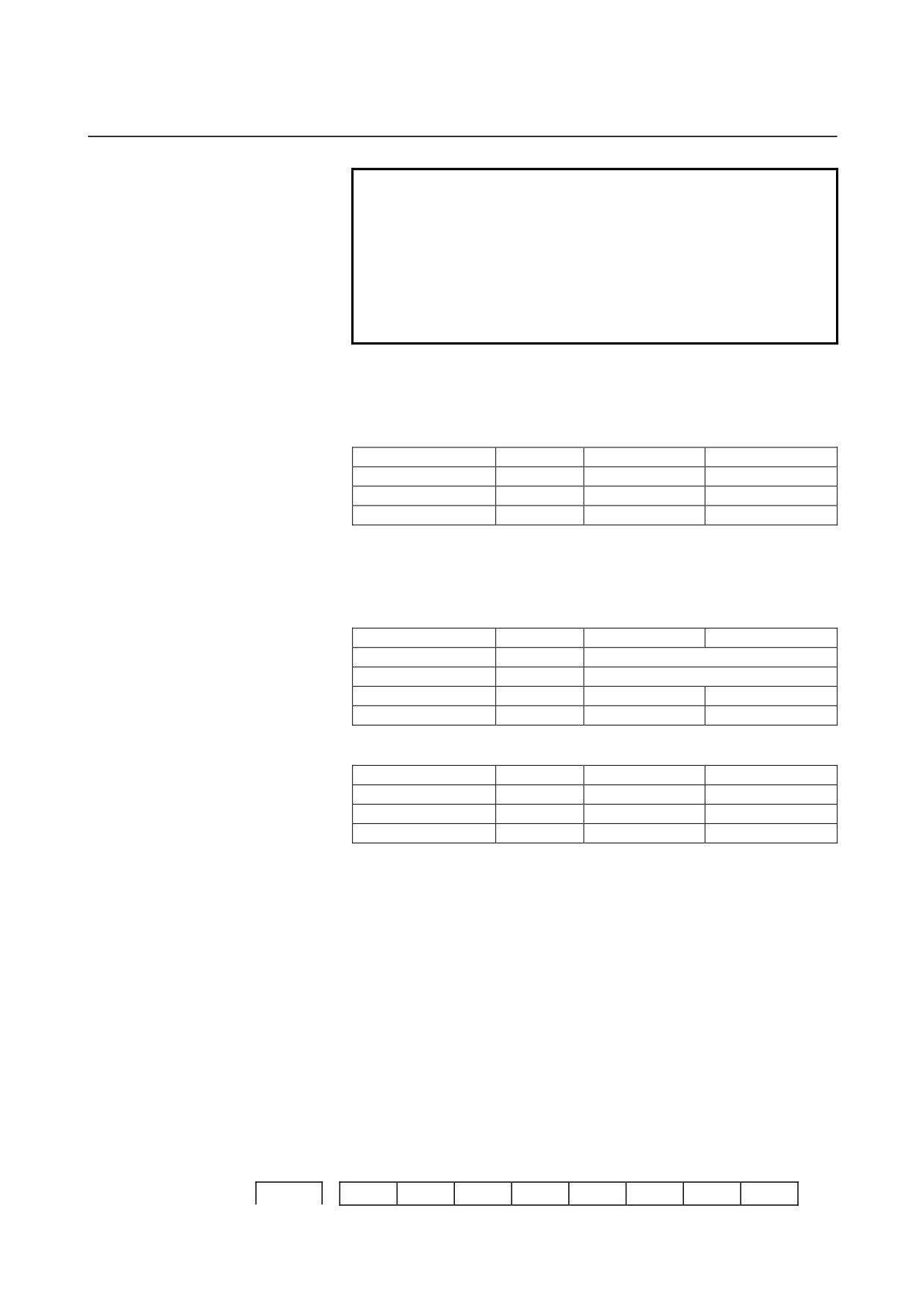
#7
#6
#5
#4
#3
#2
#1
#0
RTV
MIF
1403
NOTE
When this parameter is set, the power must be
turned off before operation is continued.
[Data type] Bit
MIF Cutting feedrates at feed per minute is specified by F commands
0: In units of 1 mm/min for millimeter machines or 0.01 inches/min
for inch machines.
1: In unit of 0.001 mm/min for millimeter machines or 0.00001
inches/min for inch machines.
NOTE
M series are not equipped with this parameter.
Cutting feedrates are specified by F commands in
units of 0.001 mm/min for millimeter machines or
0.00001 inches/min for inch machines.
RTV Override while the tool is retracting in threading
0 : Override is effective.
1 : Override is not effective.
#7
#6
#5
#4
#3
#2
#1
#0
FC0
FRV
F8A
DLF
HFC
1404
FC0
HCF
FRV
F8A
DLF
HFC
[Data type] Bit
HFC The feedrate for helical interpolation is:
0: Clamped so that the feedrates along an arc and linear axis do not
exceed the maximum cutting feedrate specified by parameter
(No.1422 or 1430).
1: Clamped so that the composite feedrate along an arc and linear
axis does not exceed the maximum cutting feedrate specified by
parameter (No.1422).
DLF After a reference position is set, manual reference position return
performed at:
0 : Rapid traverse rate (parameter No.1420)
1 : Manual rapid traverse rate (parameter No.1424)
- 61 -
4.DESCRIPTION OF PARAMETERS
B-64120EN/01
NOTE
This parameter selects a feedrate for reference
position return performed without dogs. This
parameter also selects a feedrate when manual
reference position return is performed according to
bit 7 (SJZ) of parameter No.0002 using rapid
traverse without deceleration dogs after a
reference position is set.
<For T series>
F8A
Valid data range for an F command in feed-per-minute mode
0: Range specified with bit 0 (MIF) of parameter No.1403
1:
Increment system
Units
IS-A, IS-B
IS-C
Millimeter input
mm/min
0.001 to 240000.
0.001 to 100000.
Inch input
inch/min
0.00001 to 9600.
0.00001 to 4000.
Rotation axis
deg/min
1 to 240000.
1 to 100000.
<For M series>
F8A
Valid data range for an F command with a decimal point in feed-per
minute mode
0:
Increment system
Units
IS-A, IS-B
IS-C
Millimeter input
mm/min
0.001 to 99999.999.
Inch input
inch/min
0.00001 to 999.99999.
Rotation axis (mm)
deg/min
1 to 240000.
1 to 100000.
Rotation axis (inch)
deg/min
1 to 9600.
1 to 4000.
1:
Increment system
Units
IS-A, IS-B
IS-C
Millimeter input
mm/min
0.001 to 240000.
0.001 to 100000.
Inch input
inch/min
0.00001 to 9600.
0.00001 to 4000.
Rotation axis
deg/min
1 to 240000.
1 to 100000.
FRV
For inch input, the valid range of the feedrate specified for feed per
revolution is:
0 : Standard range. (F0.000001 to 9.999999 inches per revolution)
1 : Extended to F50.0 inches per revolution.
(F0.000001 to
50.000000 inches per revolution)
HCF
In AI contour control
(M series), as the feedrate of helical
interpolation:
0 : A composite feedrate is specified.
1 : A feedrate along the arc is specified.
FC0
Specifies the behavior of the machine tool when a block (G01, G02,
G03, etc.) containing a feedrate command (F command) that is 0 is
issued during automatic operation, as follows:
0: A P/S alarm (No.011) is displayed, and the block is not executed.
1: No alarm is displayed, and the block is executed.
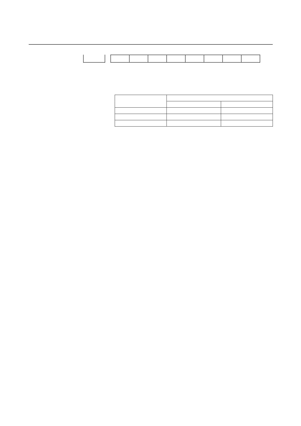
#7
#6
#5
#4
#3
#2
#1
#0
1405
FCI
EDR
- 62 -
B-64120EN/01
4.DESCRIPTION OF PARAMETERS
FCI
EDR
FD3
F1U
[Data type]
Bit
F1U
Specifies the units of the data for the parameters that set the feedrates
of the F1-digit feed commands (parameter Nos. 1451 to 1459).
Units of data
Increment system
When F1U is 0
When F1U is 1
Millimeter machine
0.1 mm/min
1 mm/min
Inch machine
0.001 inch/min
0.1 inch/min
Rotation axis
0.1 deg/min
1 deg/min
FD3
The number of significant digits of the fractional part in
the feedrate command (F command) for feed per revolution is:
0 : Up to two decimal positions (three decimal positions for inch
input).
1 : Up to three decimal positions (four decimal positions for inch
input).
EDR
Selects a parameter for setting the external deceleration applied during
interpolation type rapid traverse (bit 1 (LRP) of parameter No. 1401 =
1) .
0 : Parameter No. 1426 is used for setting the external deceleration
rate applied during interpolation type rapid traverse.
1 : The first axis of parameter No. 1427 is used for setting the
external deceleration rate applied during interpolation type rapid
traverse.
Similarly, for external deceleration 2, 3, 4, and 5, the first axis of
the external deceleration rate parameter for rapid traverse is used
if EDR is set to 1.
FCI
When the inch input and feed per revolution are set, the clamp
feedrate for cutting feed is set to:
0 :
9600 inch/min.
1 :
144000 inch/min.
- 63 -
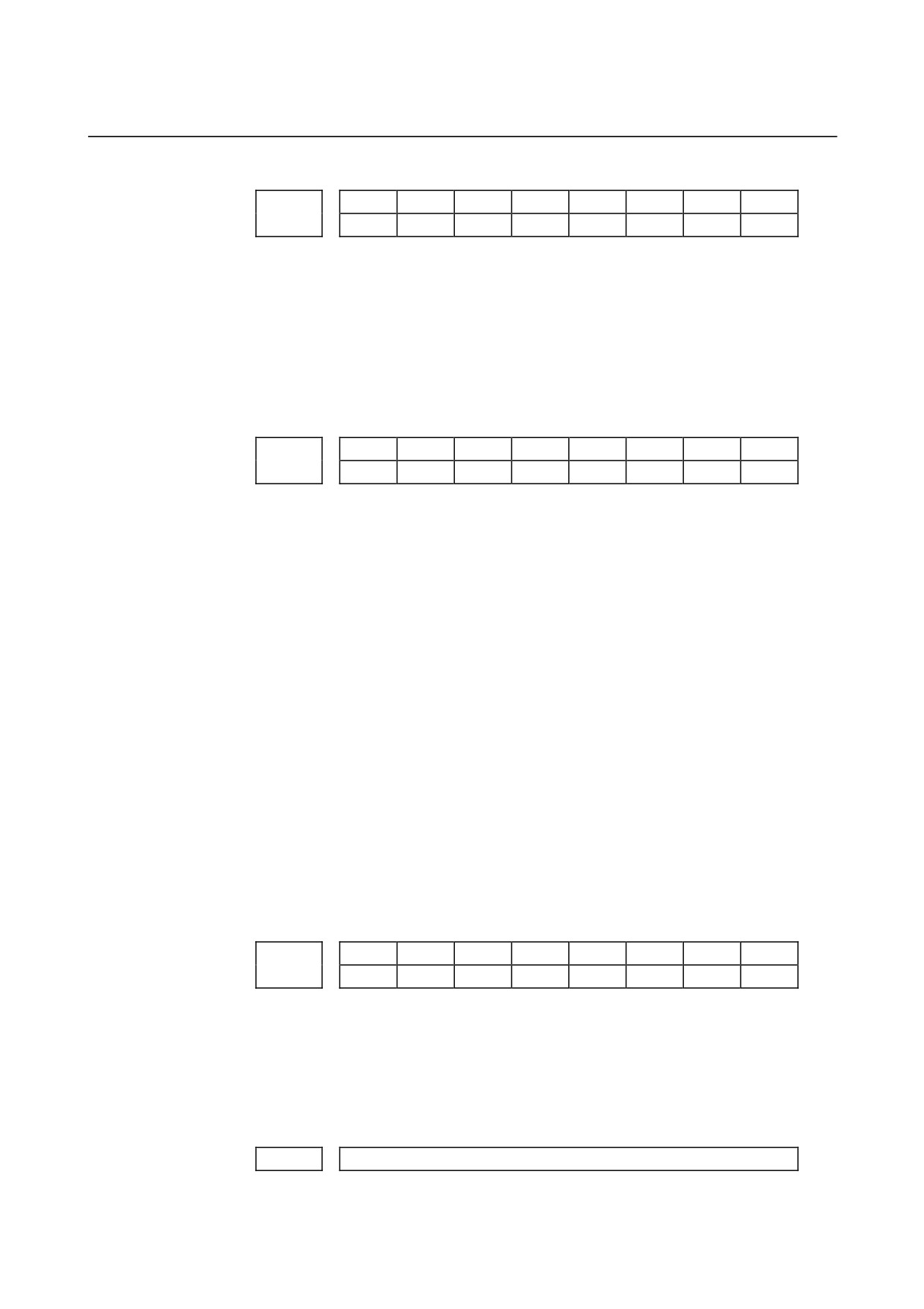
4.DESCRIPTION OF PARAMETERS
B-64120EN/01
#7
#6
#5
#4
#3
#2
#1
#0
ED3
ED2
1406
[Data type]
Bit
ED2
External deceleration 2 is:
0 : Disabled.
1 : Enabled.
ED3
External deceleration 3 is:
0 : Disabled.
1 : Enabled.
#7
#6
#5
#4
#3
#2
#1
#0
ACS
1407
ACF
ACS
[Data type]
Bit
ACS
If the reference position return for a Cs axis is not completed when
linear interpolation type positioning including the Cs axis is specified:
0 : A movement is made by non-linear interpolation type positioning
(rapid traverse is performed separately for each axis).
1 : A P/S alarm (No. 5334) is issued.
ACF
In AI advanced preview control or AI contour control mode, the
feedrate clamp value is:
0 : The setting of parameter No. 1432 or the setting of parameter No.
1422, whichever smaller.
(If one of these settings is 0, a P/S alarm (No. 5157) is issued.)
1 : The setting of parameter No. 1432 if a non-zero value is set in
parameter No. 1432.
If 0 is set in parameter No. 1432, the setting of parameter No.
1422 is used.
If
0 is set in parameter No. 1422, a P/S alarm (No. 5157) is
issued.
Parameter No. 1422 = Maximum cutting feedrate
Parameter No. 1432 = Maximum cutting feedrate for each axis in
the advanced preview control mode
#7
#6
#5
#4
#3
#2
#1
#0
1408
RFD
[Data type]
Bit axis type
RFD
The feedrate about a rotation axis is controlled:
0: In the usual method.
1: By converting the rotation speed about the rotation axis into the
travel speed on the circumference of a virtual circle.
Set the radius of the virtual circle in parameter No. 1465.
1410
Dry run rate
[Data type]
Word
- 64 -
B-64120EN/01
4.DESCRIPTION OF PARAMETERS
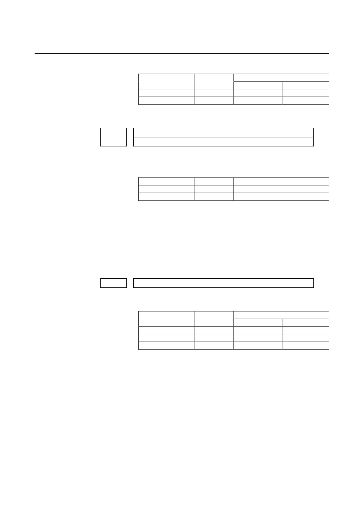
[Unit of data, valid data range]
Valid data range
Increment system
Unit of data
IS-A, IS-B
IS-C
Millimeter machine
1 mm/min
6 to 15000
6 to 12000
Inch machine
0.1 inch/min
6 to 6000
6 to 4800
Set the dry run rate when the manual feedrate is overridden by 100%.
1411
Cutting feedrate in the automatic mode at power-on (initial value)
The following parameter can be set at "Setting screen".
[Data type]
Word
[Unit of data, valid data range]
Increment system
Unit of data
Valid data range
Millimeter machine
1 mm/min
6 to 32767
Inch machine
0.1 inch/min
6 to 32767
When the machine requires little change in cutting feedrate during
cutting, a cutting feedrate can be specified in the parameter. This
eliminates the need to specify a cutting feedrate (F command) in the
NC program.
The cutting feedrate set by this parameter is valid after the CNC is
placed in the clear state by power-up or a reset until a feedrate is
specified by a program command (F command). After a feedrate is
specified by the F command, the feedrate becomes valid.
1420
Rapid traverse rate for each axis
[Data type]
2-word axis
[Unit of data, valid data range]
Valid data range
Increment system
Unit of data
IS-A, IS-B
IS-C
Millimeter machine
1 mm/min
30 to 240000
6 to 100000
Inch machine
0.1 inch/min
30 to 96000
6 to 48000
Rotation axis
1 deg/min
30 to 240000
6 to 100000
Set the rapid traverse rate when the rapid traverse override is 100% for
each axis.
- 65 -
4.DESCRIPTION OF PARAMETERS
B-64120EN/01
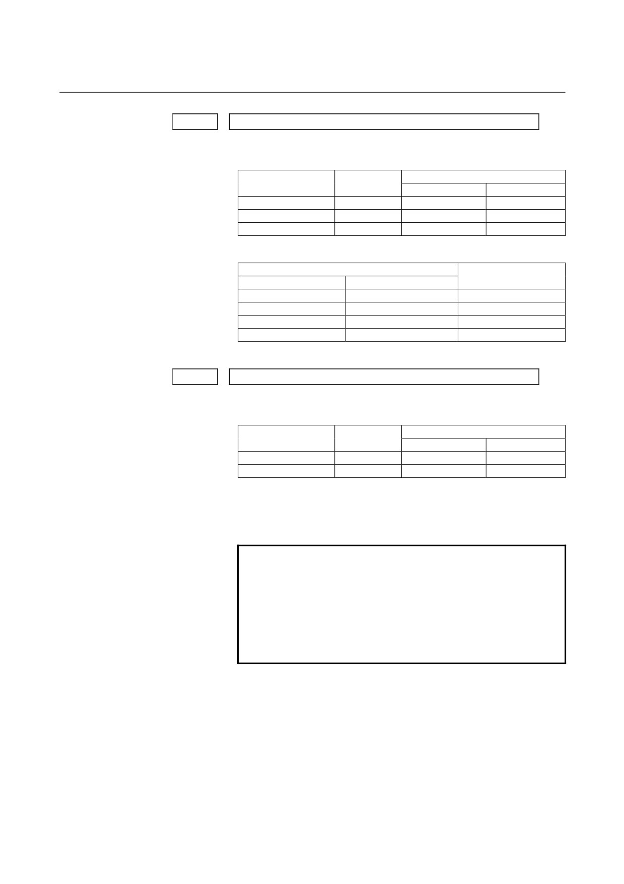
1421
F0 rate of rapid traverse override for each axis
[Data type]
Word axis
[Unit of data, valid data range]
Valid data range
Increment system
Unit of data
IS-A, IS-B
IS-C
Millimeter machine
1 mm/min
30 to 15000
30 to 12000
Inch machine
0.1 inch/min
30 to 6000
30 to 4800
Rotation axis
1 deg/min
30 to 15000
30 to 12000
Set the F0 rate of the rapid traverse override for each axis.
Rapid traverse override signal
Override value
ROV2
ROV1
0
0
100%
0
1
50%
1
0
25%
1
1
F0
F0: Parameter 1421
1422
Maximum cutting feedrate for all axes
[Data type]
2-word
[Unit of data, valid data range]
Valid data range
Increment system
Unit of data
IS-A, IS-B
IS-C
Millimeter machine
1 mm/min
6 to 240000
6 to 100000
Inch machine
0.1 inch/min
6 to 96000
6 to 48000
Specify the maximum cutting feedrate.
A feedrate in the tangential direction is clamped in cutting feed so that
it does not exceed the feedrate specified in this parameter.
NOTE
1 A maximum cutting feedrate can be specified for
each axis only during linear interpolation and
circular interpolation by using parameter No. 1430.
2 Even when parameter No. 1430 is used, clamping
to a maximum cutting feedrate based on parameter
No. 1422 is enabled during polar coordinate
interpolation and cylindrical interpolation.
- 66 -
B-64120EN/01
4.DESCRIPTION OF PARAMETERS
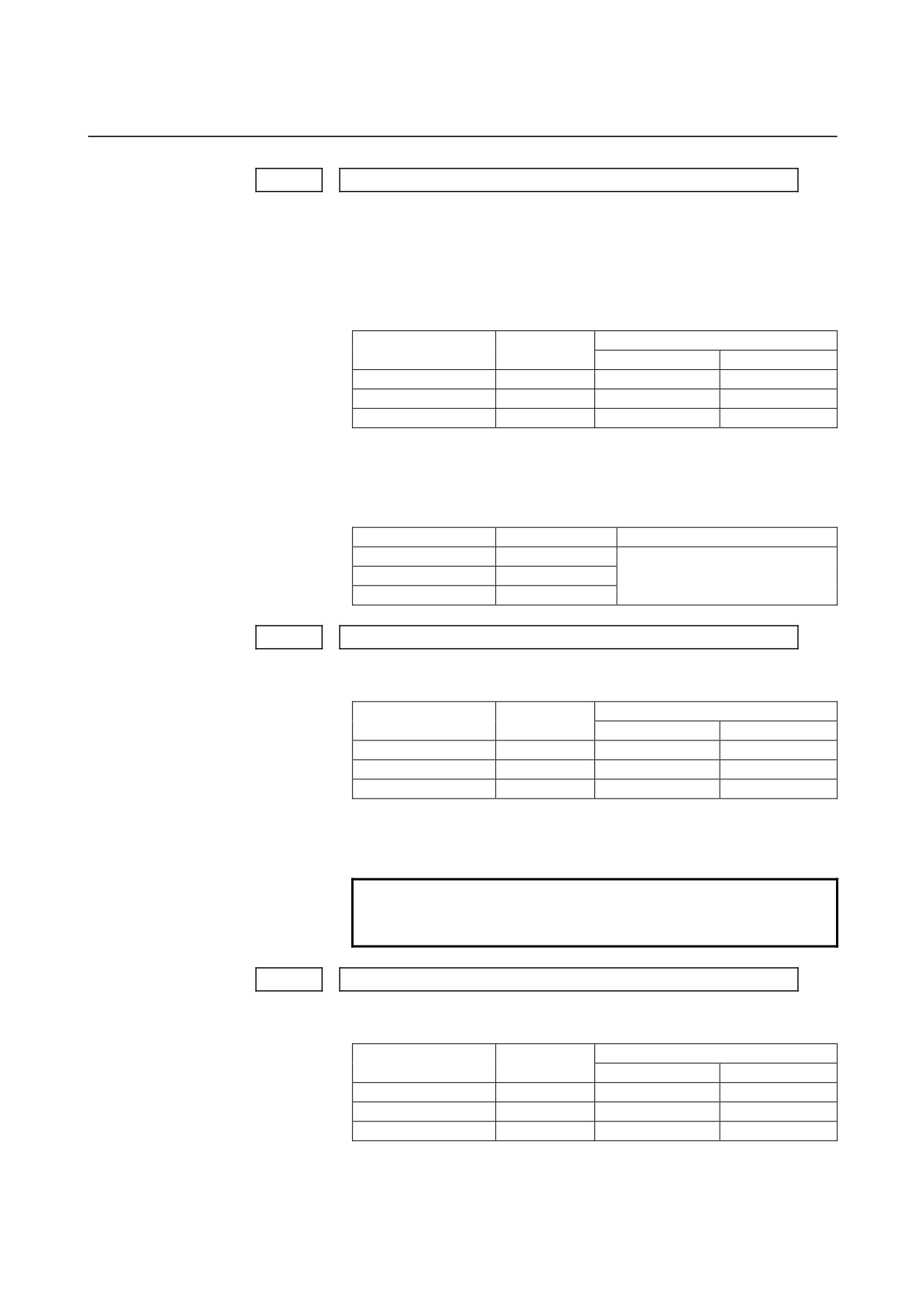
1423
Feedrate in manual continuous feed (jog feed) for each axis
[Data type]
Word axis
(1) In M series, or in T series when JRV, bit 4 of parameter No.1402,
is set to 0 (feed per minute), specify a jog feedrate at feed per
minute with an override of 100%.
[Unit of data, valid data range]
Valid data range
Increment system
Unit of data
IS-A, IS-B
IS-C
Millimeter machine
1 mm/min
6 to 15000
6 to 12000
Inch machine
0.1 inch/min
6 to 6000
6 to 4800
Rotation axis
1 deg/min
6 to 15000
6 to 12000
(2) When JRV, bit 4 of parameter No.1402, is set to 1 (feed per
revolution) in T series, specify a jog feedarate
(feed per
revolution) under an override of 100%.
[Unit of data, valid data range]
Increment system
Unit of data
Valid data range
Millimeter machine
0.01 mm/rev
Inch machine
0.001 mm/rev
0 to 32767
Rotation axis
0.01 deg/rev
1424
Manual rapid traverse rate for each axis
[Data type]
2-word axis
[Unit of data, valid data range]
Valid data range
Increment system
Unit of data
IS-A, IS-B
IS-C
Millimeter machine
1 mm/min
30 to 240000
30 to 100000
Inch machine
0.1 inch/min
30 to 96000
30 to 48000
Rotation axis
1 deg/min
30 to 240000
30 to 100000
Set the rate of manual rapid traverse when the rapid traverse override
is 100% for each axis.
NOTE
If 0 is set, the rate set in parameter 1420 is
assumed.
1425
FL rate of the reference position return for each axis
[Data type]
Word axis
[Unit of data, valid data range]
Valid data range
Increment system
Unit of data
IS-A, IS-B
IS-C
Millimeter machine
1 mm/min
6 to 15000
6 to 12000
Inch machine
0.1 inch/min
6 to 6000
6 to 4800
Rotation axis
1 deg/min
6 to 15000
6 to 12000
Set feedrate (FL rate) after deceleration when the reference position
return is performed for each axis.
- 67 -
4.DESCRIPTION OF PARAMETERS
B-64120EN/01
1426
External deceleration rate 1 of cutting feed
[Data type] Word
[Unit of data, valid data range]
Valid data range
Increment system
Unit of data
IS-A, IS-B
IS-C
Millimeter machine
1 mm/min
6 to 15000
6 to 12000
Inch machine
0.1 inch/min
6 to 6000
6 to 4800
Set the external deceleration rate of cutting feed.
1427
External deceleration rate 1 of rapid traverse for each axis
[Data type] Word axis
[Unit of data, valid data range]
Valid data range
Increment system
Unit of data
IS-A, IS-B
IS-C
Millimeter machine
1 mm/min
6 to 15000
6 to 12000
Inch machine
0.1 inch/min
6 to 6000
6 to 4800
Rotation axis
1 deg/min
6 to 15000
6 to 12000
Set the external deceleration rate of rapid traverse for each axis.
- 68 -
B-64120EN/01
4.DESCRIPTION OF PARAMETERS
1428
Reference position return feedrate
[Data type]
2-word axis
[Unit of data, valid data range]
Valid data range
Increment system
Unit of data
IS-A, IS-B
IS-C
Millimeter machine
1 mm/min
30 to 240000
6 to 100000
Inch machine
0.1 inch/min
30 to 96000
6 to 48000
Rotation axis
1 deg/min
30 to 240000
6 to 100000
This parameter sets a rapid traverse rate for reference position return
operation using deceleration dogs, or for reference position return
operation before a reference position is set.
This parameter is also used to set a feedrate for the rapid traverse
command (G00) in automatic operation before a reference position is
set.
NOTE
1 This parameter is invalid for an axis using the scale
with absolute addressing reference marks.
2 When 0 is set in this parameter, this parameter
disables the reference position return feedrate
setting function.
Before a reference position is set
After a reference position is set
No. 1428
No. 1428
=0
≠0
=0
≠0
Reference position return by G28
Raped traverse command (G00) in
No.1420
No.1420
automatic operation
No.1428
Manual reference
Without dogs (*1)
No.1420 or No.1424 (*3)
No.1424
position return
With dogs (*1)
No.1424
No.1428
Manual raped traverse
No.1423 or No.1424 (*2)
No.1424
*1 With/without dogs: Reference position return operation not
using/using deceleration dogs
*2 For manual rapid traverse before a reference position is set, a jog
feedrate
(parameter No.1423) or manual raped traverse rate
(parameter No.1424) is used according to the setting of bit 0
(RPD) of parameter No.1401.
*3 The rapid traverse rate set in parameter No.1424 or No.1420 is
used according to the setting of bit
1 (DLF) of parameter
No.1404 when reference position return is performed without
dogs, or when reference position return operation is performed
with bit 7 (SJZ) of parameter No.0002 set to 1 after a reference
position is set
(when reference position return operation is
performed using rapid traverse without deceleration dogs).
- 69 -
4.DESCRIPTION OF PARAMETERS
B-64120EN/01
1430
Maximum cutting feedrate for each axis
[Data type]
2-word axis
[Unit of data, valid data range]
Valid data range
Increment system
Unit of data
IS-A, IS-B
IS-C
Millimeter machine
1 mm/min
6 to 240000
6 to 100000
Inch machine
0.1 inch/min
6 to 96000
6 to 48000
Rotation axis
1 deg/min
6 to 240000
6 to 100000
Specify the maximum cutting feedrate for each axis.
A feedrate for each axis is clamped in cutting feed so that it does not
exceed the maximum feedrate specified for each axis.
NOTE
1 This parameter is valid only during linear
interpolation and circular interpolation. Even when
this parameter is set, clamping to a maximum
cutting feedrate based on parameter No. 1422 is
enabled during polar coordinate interpolation,
cylindrical interpolation, and involute interpolation
(M series).
2 When this parameter is set to 0 for all axes,
clamping to a maximum cutting feedrate based on
parameter No. 1422 is enabled.
This means that if a value other than 0 is set for
any of the axes with this parameter, clamping to a
maximum cutting feedrate is performed for all axes
during linear interpolation or circular interpolation
according to this parameter.
1431
Maximum cutting feedrate for all axes in the advanced preview control mode
[Data type]
2-words
[Unit of data, valid data range]
Valid data range
Increment system
Unit of data
IS-A, IS-B
IS-C
Millimeter machine
1 mm/min
0 to 240000
0 to 100000
Inch machine
0.1 inch/min
0 to 96000
0 to 48000
Rotation axis
1 deg/min
0 to 240000
0 to 100000
Specify the maximum cutting feedrate for all axes in the advanced
preview control mode.
A feedrate in the tangential direction is clamped in cutting feed so that
it does not exceed the feedrate specified in this parameter.
- 70 -
B-64120EN/01
4.DESCRIPTION OF PARAMETERS
NOTE
1 To specify the maximum cutting feedrate for each
axis, use parameter No.1432 instead.
2 In a mode other than the look-ahead mode, the
maximum cutting feedrate specified in parameter
No.1422 or No.1430 is applied and the feedrate is
clamped at the maximum feedrate.
Maximum cutting feedrate for each axis in the advanced preview control mode
1432
Maximum cutting feedrate for each axis in the AI advanced preview control / AI
contour control mode or advanced preview control mode
[Data type]
2-word axis
[Unit of data, valid data range]
Valid data range
Increment system
Unit of data
IS-A, IS-B
IS-C
Millimeter machine
1 mm/min
0 to 240000
0 to 100000
Inch machine
0.1 inch/min
0 to 96000
0 to 48000
Rotation axis
1 deg/min
0 to 240000
0 to 100000
Specify the maximum cutting feedrate for each axis in the AI
advanced preview control / AI contour control mode or advanced
preview control mode.
A feedrate for each axis is clamped during cutting feed so that it does
not exceed the maximum cutting feedrate specified for each axis.
NOTE
1 This parameter is effective only in linear and
circular interpolation. In polar coordinate and
cylindrical interpolation, the maximum feedrate for
all axes specified in parameter No.1431 is
effective.
2 If a setting for each axis is 0, the maximum
feedrate specified in parameter No.1431 is applied
to all axes and the feedrate is clamped at the
maximum feedrate.
3 In a mode other than the AI advanced preview
control / AI contour control mode or advanced
preview mode, the maximum cutting feedrate
specified in parameter No.1422 or No.1430 is
applied and the feedrate is clamped at the
maximum feedrate.
- 71 -
4.DESCRIPTION OF PARAMETERS
B-64120EN/01
Maximum speed for each axis for the speed check function
1436
[Data type]
2-word axis
[Unit of data, valid data range]
Valid data range
Increment system
Unit of data
IS-A, IS-B
IS-C
Millimeter machine
1 mm/min
0,30 to 240000
0,6 to 100000
Inch machine
0.1 inch/min
0,30 to 96000
0,6 to 48000
Rotation axis
1 deg/min
0,30 to 240000
0,6 to 100000
If 0 is set, this function is disabled.
Set the maximum speed for each axis. If the speed set in this
parameter is exceeded, a P/S alarm (No. 5323) indicating an excessive
speed is issued, and the movement is decelerated then stopped.
The speed check function checks data obtained by converting this
parameter value to the amount of a movement made every 8 ms.
1440
External deceleration rate 2 of cutting feed
[Data type]
Word
[Unit of data, valid data range]
Valid data range
Increment system
Unit of data
IS-A, IS-B
IS-C
Millimeter machine
1 mm/min
6 to 15000
6 to 12000
Inch machine
0.1 inch/min
6 to 6000
6 to 4800
Set the external deceleration rate of cutting feed.
1441
External deceleration rate 2 of rapid traverse for each axis
[Data type]
Word axis
[Unit of data, valid data range]
Valid data range
Increment system
Unit of data
IS-A, IS-B
IS-C
Millimeter machine
1 mm/min
6 to 15000
6 to 12000
Inch machine
0.1 inch/min
6 to 6000
6 to 4800
Rotation axis
1 deg/min
6 to 15000
6 to 12000
Set the external deceleration rate of rapid traverse for each axis.
- 72 -
B-64120EN/01
4.DESCRIPTION OF PARAMETERS
1442
Maximum feedrate 2 of manual handle feed for each axis
[Data type]
Word axis
[Unit of data, valid data range]
Valid data range
Increment system
Unit of data
IS-A, IS-B
IS-C
Millimeter machine
1 mm/min
6 to 15000
6 to 12000
Inch machine
0.1 inch/min
6 to 6000
6 to 4800
Rotation axis
1 deg/min
6 to 15000
6 to 12000
Set the maximum feedrate of manual handle feed for each axis.
1443
External deceleration rate 3 of cutting feed
[Data type]
Word
[Unit of data, valid data range]
Valid data range
Increment system
Unit of data
IS-A, IS-B
IS-C
Millimeter machine
1 mm/min
6 to 15000
6 to 12000
Inch machine
0.1 inch/min
6 to 6000
6 to 4800
Set the external deceleration rate of cutting feed.
1444
External deceleration rate 3 of rapid traverse for each axis
[Data type]
Word axis
[Unit of data, valid data range]
Valid data range
Increment system
Unit of data
IS-A, IS-B
IS-C
Millimeter machine
1 mm/min
6 to 15000
6 to 12000
Inch machine
0.1 inch/min
6 to 6000
6 to 4800
Rotation axis
1 deg/min
6 to 15000
6 to 12000
Set the external deceleration rate of rapid traverse for each axis.
1445
Maximum feedrate 3 of manual handle feed for each axis
[Data type]
Word axis
[Unit of data, valid data range]
Valid data range
Increment system
Unit of data
IS-A, IS-B
IS-C
Millimeter machine
1 mm/min
6 to 15000
6 to 12000
Inch machine
0.1 inch/min
6 to 6000
6 to 4800
Rotation axis
1 deg/min
6 to 15000
6 to 12000
Set the maximum feedrate of manual handle feed for each axis.
- 73 -
4.DESCRIPTION OF PARAMETERS
B-64120EN/01
Change of feedrate for one graduation on the manual pulse generator during
1450
F1 digit feed
[Data type] Byte
[Valid data range]
1 to 127
Set the constant that determines the change in feedrate as the manual
pulse generator is rotated one graduation during F1-digit feed.
F
axi
∆F = m
(where, i=1 or 2)
100n
In the above equation, set n. That is, the number of revolutions
of the manual pulse generator, required to reach feedrate Fmaxi is
obtained. Fmaxi refers to the upper limit of the feedrate for an F1-digit
feed command, and set it in parameter 1460 or 1461.
Fmax1: Upper limit of the feedrate for F1 to F4 (parameter 1460)
Fmax2: Upper limit of the feedrate for F5 to F9 (parameter 1461)
- 74 -
B-64120EN/01
4.DESCRIPTION OF PARAMETERS
1451
Feedrate for F1 digit command F1
1452
Feedrate for F1 digit command F2
1453
Feedrate for F1 digit command F3
1454
Feedrate for F1 digit command F4
1455
Feedrate for F1 digit command F5
1456
Feedrate for F1 digit command F6
1457
Feedrate for F1 digit command F7
1458
Feedrate for F1 digit command F8
1459
Feedrate for F1 digit command F9
The following parameter can be set at "Setting screen".
[Data type]
2-word
[Unit of data, valid data range]
(1) When the F1U parameter (bit 0 of parameter No.1405) is 0
Valid data range
Increment system
Unit of data
IS-A, IS-B
IS-C
Millimeter machine
0.1 mm/min
6 to 150000
6 to 120000
Inch machine
0.01 inch/min
6 to 60000
6 to 48000
Rotation axis
0.1 deg/min
6 to 150000
6 to 120000
(2) When the F1U parameter (bit 0 of parameter No.1405) is 1
Valid data range
Increment system
Unit of data
IS-A, IS-B
IS-C
Millimeter machine
1 mm/min
6 to 15000
6 to 12000
Inch machine
0.1 inch/min
6 to 6000
6 to 4800
Rotation axis
1 deg/min
6 to 15000
6 to 12000
These parameters set the feedrates for 1-digit feed commands F1 to F9.
When an 1-digit feed command is specified, and the feedrate is
changed by turning the manual pulse generator, the parameter-set
value also changes accordingly.
- 75 -
4.DESCRIPTION OF PARAMETERS
B-64120EN/01
1460
Upper limit of feedrate for the one-digit F code command (F1 to F4)
1461
Upper limit of feedrate for the one-digit F code command (F5 to F9)
[Data type]
2-word
[Unit of data, valid data range]
Valid data range
Increment system
Unit of data
IS-A, IS-B
IS-C
Millimeter machine
1 mm/min
6 to 15000
6 to 12000
Inch machine
0.1 inch/min
6 to 6000
6 to 4800
Rotation axis
1 deg/min
6 to 15000
6 to 12000
Set the upper limit of feedrate for the F1-digit feed command.
As the feedrate increases by turning the manual pulse generator, the
feedrate is clamped when it reaches the upper limit set. If an F1-digit
feed command F1 to F4 is executed, the upper limit is that set in
parameter 1460. If an F1-digit command F5 to F9 is executed, the
upper limit is that set in parameter 1461.
- 76 -
B-64120EN/01
4.DESCRIPTION OF PARAMETERS
1465
Virtual radius for feedrate control about rotation axis
[Data type]
2-word axis
[Unit of data]
Increment system
IS-A
IS-B
IS-C
Unit
Metric input
mm
0.01
0.001
0.0001
Inch input
inch
[Valid data range]
0 to 99999999
Set the radius of a virtual circle when using such a control method that
the feedrate of a rotation axis is converted to a travel speed on a circle
of a virtual radius.
NOTE
1 Note that the increment system remains
unchanged regardless of whether metric input or
inch input is used.
2 This function is enabled when bit 0 (ROTx) of
parameter No. 1006 and bit 0 (RFDx) of parameter
No. 1408 are set to 1.
3 Be careful when setting bit 0 (RFDx) of parameter
No. 1408 and parameter No. 1465 (virtual radius).
In particular, when this function is used with a small
virtual radius value, axis movement speeds up.
4 If a large value is set for the amount of travel and
parameter No. 1465 (virtual radius), an alarm (P/S
5307: Internal data exceeded an allowable range.)
is issued.
5 This function cannot be used in the following
modes:
Rapid traverse, inverse time feed (G93), feed per
revolution (G94), threading, AI advanced preview
control, AI contour control
- 77 -
4.DESCRIPTION OF PARAMETERS
B-64120EN/01
Feedrate of retraction in the threading cycle
1466
[Data type]
2-word
[Unit of data, valid data range]
Valid data range
Increment system
Unit of data
IS-A, IS-B
IS-C
Millimeter machine
1 mm/min
30 to 240000
6 to 100000
Inch machine
0.1 inch/min
30 to 96000
6 to 48000
Rotation axis
1 deg/min
30 to 240000
6 to 100000
Set the feedrate of retraction in a threading cycle.
If 0 is set in this parameter, a movement is made at the feedrate (rapid
traverse rate) set in parameter No. 1420.
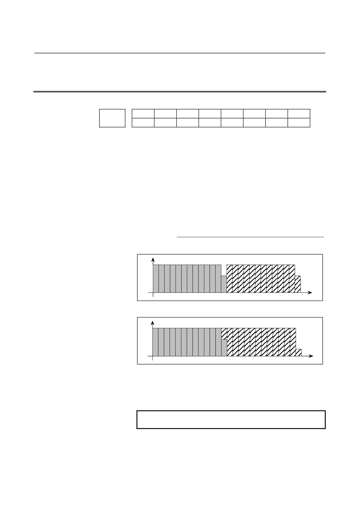
[Example]
When G92 is specified
R1
Start
point
R2
R1
C
C
In the above figure, R1 denotes the rapid traverse rate, and C denotes
the cutting feedrate.
Feedrate R2 is set by this parameter. If 0 is set in this parameter, R2 is
the same feedrate as R1.
- 78 -
B-64120EN/01
4.DESCRIPTION OF PARAMETERS
4.14 PARAMETERS OF ACCELERATION/DECELERATION
CONTROL
#7
#6
#5
#4
#3
#2
#1
#0
NCI
RTO
1601
ACD
NCI
RTO
OVB
[Data type] Bit
OVB Block overlap in cutting feed
0: Blocks are not overlapped in cutting feed.
1: Blocks are overlapped in cutting feed.
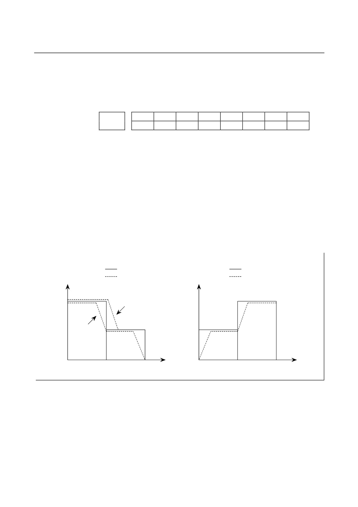
Block overlap outputs the pulses remaining at the end of pulse
distribution in a block together with distribution pulses in the next
block. This eliminates changes in feedrates between blocks.
Block overlap is enabled when blocks containing G01, G02, or G03
are consecutively specified in G64 mode. If minute blocks, however,
are specified consecutively, overlap may not be performed.
The following pulses in block F2 are added to the pulses remaining at
the end of pulse distribution in block F1.
(Number of pulses required at the end of block F1)
(Number of pulses to be added) = F2 ×
F1
When F1 = F2
F
F1
F2
t
When block overlap is disabled
F
F1
F2
t
When block overlap is enabled
RTO Block overlap in rapid traverse
0 : Blocks are not overlapped in rapid traverse.
1 : Blocks are overlapped in rapid traverse.
NOTE
See the description of parameter No.1722.
NCI In-position check at deceleration
0 : Performed
1 : Not performed
- 79 -
4.DESCRIPTION OF PARAMETERS
B-64120EN/01
ACD Function for automatically reducing the feedrate at corners (automatic
corner override function)
0 : The function is not used.
1 : The function is used.
#7
#6
#5
#4
#3
#2
#1
#0
LS2
G8S
CSD
FWB
1602
LS2
G8S
CSD
BS2
COV
FWB
[Data type] Bit
FWB Cutting feed acceleration/deceleration before interpolation
0 : Type A of acceleration/deceleration before interpolation is used.
1 : Type B of acceleration/deceleration before interpolation is used.
Type A:
When a feedrate is to be changed by a command, acceleration/
deceleration starts after the program enters the block in which the
command is specified.
Type B:
When a feedrate is to be changed by a command, deceleration
starts and terminates at the block before the block in which the
command is specified.
When a feedrate is to be changed by a command, acceleration
starts after the program enters the block in which the command is
specified.
<Example of a deceleration process>
<Example of a acceleration process>
Specified feedrate
Specified feedrate
Feedrate after
Feedrate after
Feedrate
Feedrate
acceleration/deceleration
acceleration/deceleration
before interpolation is applied
before interpolation is applied
Point 1
F3
Type A
F3
F2
Type B
F2
F1
Time F1
Time
N1
N2
N1
N2
To change the feedrate from F3 to F2, it is necessary to start reducing the feedrate at point 1.
COV The outer arc cutting feedrate change function of the automatic corner
override function is:
0 : Not used.
1 : Used.
BS2 The type of acceleration/deceleration after interpolation in cutting feed
in advanced preview control mode is:
0 : Specified by bit 6 (LS2) of parameter No. 1602.
1 : Bell-shaped acceleration/deceleration.
- 80 -
B-64120EN/01
4.DESCRIPTION OF PARAMETERS
BS2
LS2
Acceleration/deceleration
0
0
Exponential acceleration/deceleration after interpolation
0
1
Linear acceleration/deceleration after interpolation
Bell-shaped acceleration/deceleration after interpolation.
1
0
(The option for bell-shaped acceleration/deceleration after
interpolation for cutting feed is required.)
CSD
In the function for automatically reducing a feedrate at corners,
0 : Angles are used for controlling the feedrate.
1 : Differences in feedrates are used for controlling the feedrate.
G8S
Serial spindle advanced preview control is:
0 : Disabled.
1 : Enabled.
When enabled, advanced preview control can be applied to the
following functions:
•
Rigid tapping
•
Cs contour control
•
Spindle positioning (only when bit 3 of parameter No.1800 is 1)
NOTE
For Cs contour control and rigid tapping, advanced
preview control is valid only for the first spindle. Cs
contour control and rigid tapping with the second
spindle does not support advanced preview control.
LS2
Type of acceleration/deceleration after interpolation in cutting feed in
advanced preview control, AI advanced preview control, or AI
contour control mode
0 : Exponential acceleration/deceleration is applied
(advanced
preview control), or no acceleration/deceleration is applied (AI
advanced preview control and AI contour control).
1 : Linear acceleration/deceleration is applied.
#7
#6
#5
#4
#3
#2
#1
#0
RPT
1603
BEL
RBL
RPT
[Data type]
Bit
PRT
The acceleration/deceleration of interpolation-type rapid traverse is
performed:
0: With a constant inclination.
1: With a constant time.
NOTE
1 The acceleration/deceleration time constant and
override for rapid traverse are used.
2 Rapid traverse block overlap cannot be used.
RBL
In the AI advanced preview control
/ AI contour control,
acceleration/deceleration of rapid traverse is:
0: Linear acceleration/deceleration.
- 81 -