FANUC Series 0i-MODEL C, Series 0i Mate-MODEL C. PARAMETER MANUAL (B-64120EN/01) - page 9
4.DESCRIPTION OF PARAMETERS
B-64120EN/01
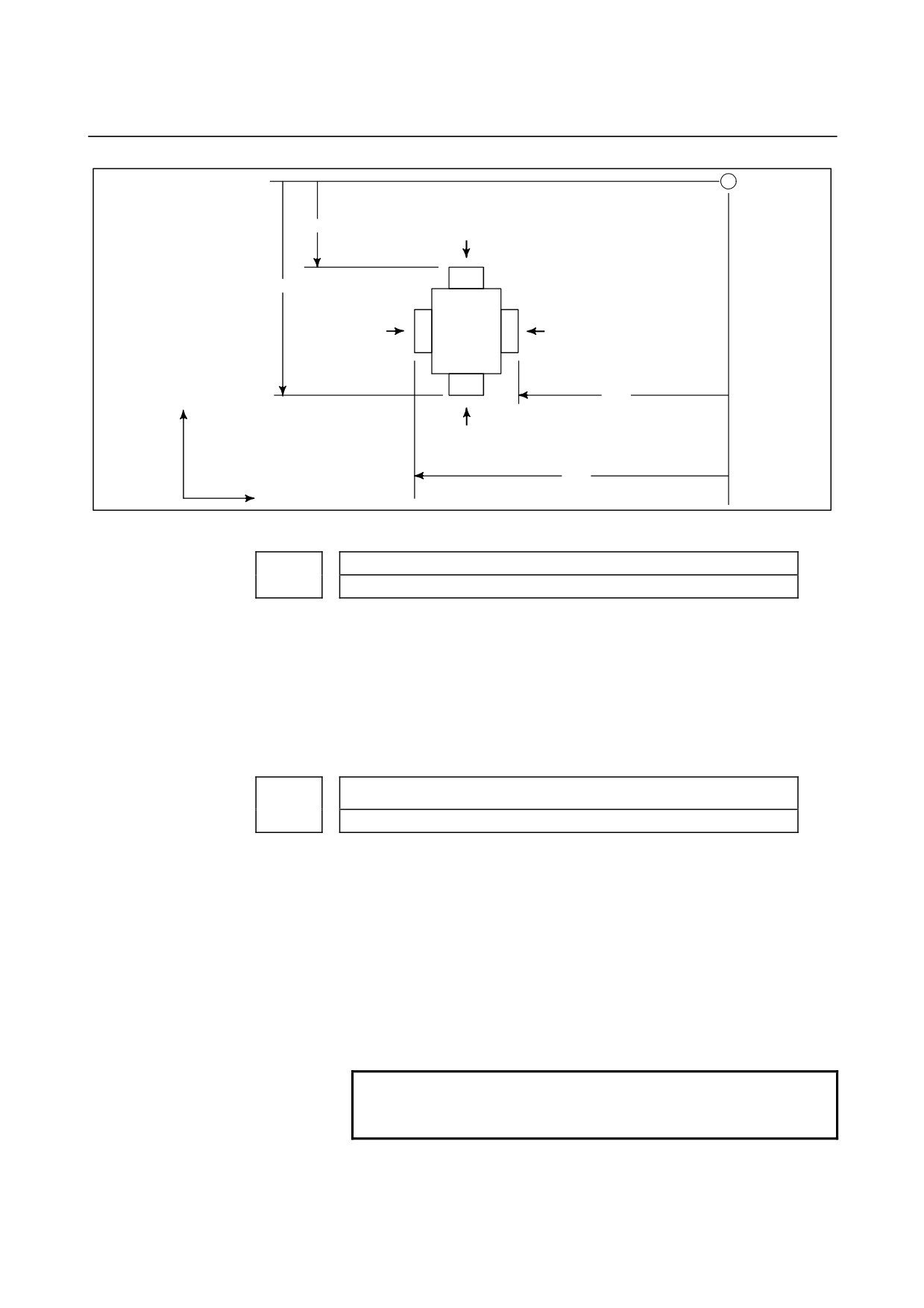
measurement
reference
position
Xm
X-axis -contact face
Xp
Z-axis +contact
Z-axis -contact face
face
Zm
+X
X-axis +contact face
Zp
+Z
Fig.4.21 Distance along X and Z Axes from the Reference Position to +/- Contact Surfaces
Tool offset number used for the input of tool offset value measured B
5020
[Data type]
Byte
[Valid data range]
1 to the maximum number of tool compensation sets
Set a tool offset number to be used for setting the amount by which
the workpiece coordinate system is shifted by the tool compensation
direct input B function. This parameter is valid when the tool offset
number is not selected automatically (QNI, #5 of parameter 5005, is
zero).
Number of pulse interpolation cycles memorized prior to contacting the
touch sensor
5021
[Data type]
Byte
[Unit of data]
Interpolation cycle
[Valid data range]
0 to 8
When the error prevention function in the tool compensation direct
input B function is used, or when a touch sensor with single-contact
signal input is used, this parameter sets the number of interpolation
cycles of pulses stored immediately before the tool is brought into
contact with the touch sensor by manual operation.
If
0 is set for this parameter, the specification of
8 (maximum
allowable value) is assumed.
NOTE
This parameter is enabled when the TS1
parameter (bit 3 of parameter No.5004) is set to 1.
- 232 -
B-64120EN/01
4.DESCRIPTION OF PARAMETERS
5030
Minimum grinding wheel diameter in minimum grinding wheel diameter
check
[Data type]
2-word
[Unit of data]
Input increment
IS-A
IS-B
IS-C
Unit
Millimeter input
0.01
0.001
0.0001
mm
Inch input
0.001
0.0001
0.00001
inch
[Valid data range]
Input increment
IS-A, IS-B
IS-C
Millimeter input
-999999 to 999999
-9999999 to 9999999
Inch input
-999999 to 999999
-9999999 to 9999999
If the compensation value corresponding to an offset number specified
by an H code is smaller than the minimum grinding wheel diameter
specified in this parameter during compensation with G43 or G44, the
signal F0065#3 GWLF is output to the PMC.
NOTE
This is a parameter for cylindrical grinding
machines.
#7
#6
#5
#4
#3
#2
#1
#0
OWD
5040
NOTE
When this parameter has been set, the power must
be turned off before operation is continued.
[Data type]
Bit
OWD
In radius programming (bit 1 (ORC) of parameter No. 5004 is set to
1),
0 : Tool offset values of both geometry compensation and wear
compensation are specified by radius.
1 : Tool offset value of geometry compensation is specified by
radius and tool offset value of wear compensation is specified by
diameter, for an axis of diameter programming.
#7
#6
#5
#4
#3
#2
#1
#0
CRS
5041
NM2
UMD
[Data type]
Bit
UMD
If a program contains no D command in cutter compensation C:
0 : Compensation data is not updated.
1 : If G41 or G42 command is present, the value of modal D is used
as a compensation number to update compensation data.
- 233 -
4.DESCRIPTION OF PARAMETERS
B-64120EN/01
CRS If a startup with a travel distance of 0 is performed after a reference
position return operation when a T code specifying a virtual tool tip
number other than 0 and 9 is specified, the startup block operation is
as follows:
0 : The block does not make any movement.
1 : The block makes a movement so that the tool tip center is placed
at the current coordinates.
NOTE
If the virtual tool tip number is 0 or 9, a movement
is made so that the tool tip center is placed at the
current coordinates, regardless of the setting of this
parameter.
NM2 When two or more blocks that specify no movement are specified
successively, or when an M code not buffered is specified in one
block:
0 : No alarm is issued.
1 : An alarm is issued. (P/S 041 alarm)
- 234 -
B-64120EN/01
4.DESCRIPTION OF PARAMETERS
4.22
PARAMETERS OF CANNED CYCLES
4.22.1
Parameter of canned Cycle for Drilling
#7
#6
#5
#4
#3
#2
#1
#0
M5T
ILV
RTR
FXY
5101
M5B
M5T
RD2
RD1
EXC
FXY
[Data type]
Bit
FXY
The drilling axis in the drilling canned cycle is:
0 : Always the Z-axis
1 : The axis selected by the program
NOTE
In the case of the T series, this parameter is valid
only for the drilling canned cycle in the FS10/11
format.
EXC
G81
0 : Specifies a drilling canned cycle
1 : Specifies an external operation command
RTR
G83 and G87
0 : Specify a high-speed peck drilling cycle
1 : Specify a peck drilling cycle
ILV
Initial point position in drilling canned cycle
0 : Not updated by reset
1 : Updated by reset
RD2, RD1
Set the axis and direction in which the tool in drilling canned cycle
G76 or G87 is got free. RD2 and RD1 are set as shown below by
plane selection.
RD2
RD1
G17
G18
G19
0
0
+X
+Z
+Y
0
1
-X
-Z
-Y
1
0
+Y
+X
+Z
1
1
-Y
-X
-Z
M5T
When a spindle rotates from the forward to the reverse direction and
vice versa in tapping cycles G84 and G74 for M series (G84 and G88
for T series), before M04 or M03 is output:
For T series
0 : Not output M05
1 : Outputs M05
For M series
0 : Outputs M05
1 : Not output M05
M5B
In drilling canned cycles G76 and G87:
0 : Outputs M05 before an oriented spindle stops
1 : Not output M05 before an oriented spindle stops
- 235 -
4.DESCRIPTION OF PARAMETERS
B-64120EN/01
#7
#6
#5
#4
#3
#2
#1
#0
RDI
RAB
K0E
RFC
F16
QSR
MRC
5102
[Data type]
Bit
MRC
When a target figure other than a monotonically increasing or
monotonically decreasing figure is specified in a multiple repetitive
turning canned cycle (G71, G72):
0 : No alarm occurs.
1 : P/S alarm No.064 is occurs.
NOTE
This parameter is valid for multiple repetitive
turning canned cycle type I.
QSR
Before a multiple repetitive canned cycle (G70 to G73) is started, a
check to see if the program contains a block that has the sequence
number specified in address Q is:
0 : Not made.
1 : Made. (If the sequence number specified in address Q cannot be
found, an alarm occurs and the canned cycle is not executed.)
F16
When the FS10/11 format is used (with bit 1 (FCV) of parameter
No.0001 set to 1), a canned drilling cycle is specified using :
0 : FS10/11 format
1 : FS0 format.
(However, the number of repetitions is specified
using address L.)
RFC
For the semifinish figure of G71 or G72 and for a cutting pattern of
G73, tool-nose radius compensation is:
0 : Not performed.
1 : Performed.
K0E
When K0 is specified in a hole machining canned cycle (G80 to G89):
0 : Hole machining is performed once.
1 : Hole machining is not performed. Instead, the hole machining
data is merely memorized.
RAB
The R command for the drilling canned cycle in the Series 15 format
is:
0 : Regarded as an incremental command
1 : Regarded as:
An absolute command in the case of G code system A
An absolute command in the case of G code system B or C when
the G90 mode is specified.
An incremental command in the case of G code system B or C
when the G91 mode is specified.
RDI
The R command for the drilling canned cycle in the FS10/11 format:
0 : Is regarded as the specification of a radius
1 : Follows the specification of a diameter/radius for the drilling axis
#7
#6
#5
#4
#3
#2
#1
#0
TCZ
CID
COD
PNA
P15
TFD
5103
TCZ
DCP
QZA
SIJ
- 236 -
B-64120EN/01
4.DESCRIPTION OF PARAMETERS
[Data type]
Bit
SIJ
When the FS10/11 command format is used, a tool shift value for the
drilling canned cycle G76 or G87 is specified by:
0 : Address Q
1 : Address I, J, or K
TFD
During a threading cycle, feed forward is:
0 : Enabled.
1 : Disabled.
QZA
When the specification of the depth of cut (Q) for each time is omitted,
or if Q0 is specified in a high-speed peck drilling canned cycle (G73)
or peck drilling canned cycle (G83):
0 : No alarm is issued.
1 : An alarm (No.045) is issued.
P15
When the FS10/11 command format is used, the machining sequence
for pocketing using multiple repetitive canned cycle G71 or G72
follows:
0 : FS0(FS16) specification
1 : FS10/11 specification
DCP
When an axis perpendicular to or an axis parallel to a specified plane
is specified in a canned cycle for drilling:
0 : The specified axis is regarded as the drilling axis.
1 : The specified axis is regarded as the positioning axis.
PNA
If the FS10/11 tape format is used and if a plane without an axis is
specified in the canned cycle mode of drilling, an alarm is:
0 : Raised.
(P/S 028)
1 : Not raised.
COD
In pocketing, the sequence of axis movements made to return the tool
to the start point at the end of machining is as follows:
0 : X-axis to Z-axis
1 : Z-axis to X-axis
NOTE
If this parameter is set to 1, specifying G71 causes
the tool to return to the start point in the sequence
from Z-axis to X-axis. Therefore, when the tool
returns to the start point after end facing,
interference between the tool and workpiece
surface can be prevented.
CID
When the FS10/11 command format is used, application of the setting
of bit 7 (IPR) of parameter No. 1004 to the depth of cut in a multiple
repetitive turning canned cycle is:
0 : Disabled.
1 : Enabled.
TCZ
In a tapping cycle (excluding rigid tapping), an accumulated zero
check in the tapping step (forward, backward) is:
0 : Not performed.
1 : Performed.
Execute a tapping cycle (excluding rigid tapping) with the
servo feed forward (bit 1 of parameter No. 2005). If an impact is
detected, set this parameter to 1.
- 237 -

4.DESCRIPTION OF PARAMETERS
B-64120EN/01
#7
#6
#5
#4
#3
#2
#1
#0
PCT
MCC
SPE
FCK
BCR
5104
RDC
[Data type]
Bit
RDC
A canned cycle for high-speed positioning and drilling is:
0 : Disabled.
1 : Enabled.
BCR
In a boring cycle, retraction is made:
0 : At a cutting feedrate.
1 : At a rapid traverse rate.
FCK
In a multiple repetitive canned cycle (G71/G72), the machining profile
is:
0 : Not checked.
1 : Checked.
If this parameter is specified, the machining profile specified in the
multiple repetitive canned cycle for lathe
(G71/G72) and the
machining start point are checked. If the relationship is incorrect, the
P/S 062 alarm is raised.
An incorrect relationship between the machining profile and
machining start point indicates either of the following cases.
• Although the finishing allowance is specified with a positive sign,
the start point of the canned cycle is smaller than the maximum
value of the machining profile.
•
Although the finishing allowance is specified with a negative
sign, the start point of the canned cycle is larger than the
minimum value of the machining profile.
NOTE
1 The machining profile is checked before the
operation of the canned cycle (not during
machining).
2 The machining profile to be checked is a
programmed profile. The path of retraction or return
is not checked.
3 This parameter is not valid for G71 or G72 of the
canned cycle for grinder.
SPE
In a multiple repetitive threading cycle in the FS10/11 tape format,
single-edge thread cutting and both-edge zigzag thread cutting with
the depth of cut kept constant:
0 : Cannot be specified.
1 : Can be specified.
MCC
In a multiple repetitive turning canned cycle (G71 or G72), whether an
illegal arc is specified or not is:
0 : Not checked immediately before the start of a movement.
1 : Checked immediately before the start of a movement.
- 238 -

B-64120EN/01
4.DESCRIPTION OF PARAMETERS
NOTE
1 This parameter is valid when bit 1 (MRC) of
parameter No. 5102 is set to 1.
2 Regardless of the setting of this parameter, the
shape is checked during a movement made by an
arc command.
PCT
A Q command in a tapping cycle (G84 or G88) is:
0 : Invalid.
1 : Valid. (A peck tapping cycle is performed.)
When this parameter is set, and the depth of cut for each time is
specified with address Q in G84 or G88, a peck tapping cycle is
performed.
As a peck tapping cycle operation, high-speed peck tapping or peck
tapping can be selected by bit 5 (PCP) of parameter No. 5200. This
function can be used for both tapping and rigid tapping. Even when
this parameter is set, ordinary tapping or rigid tapping is performed if
Q is not specified or if Q0 is specified.
C-axis clamp M code in drilling canned cycle
5110
[Data type]
2-word
[Valid data range]
0 to 99
This parameter sets the C-axis clamp M code in a drilling canned
cycle.
Dwell time when C-axis unclamping is specified in drilling canned cycle
5111
[Data type]
Word
[Unit of data]
ms
[Valid data range]
0 to 32767
This parameter sets the dwell time when C-axis unclamping is
specified in a drilling canned cycle.
- 239 -
4.DESCRIPTION OF PARAMETERS
B-64120EN/01
Spindle forward-rotation M code in drilling canned cycle
5112
[Data type]
2-word
[Valid data range]
0 to 255
This parameter sets the spindle forward-rotation M code in a drilling
canned cycle.
NOTE
M03 is output when "0" is set.
Spindle reverse-rotation M code in drilling canned cycle
5113
[Data type]
2-word
[Valid data range]
0 to 255
This parameter sets the spindle reverse-rotation M code in
a drilling canned cycle.
NOTE
M04 is output when "0" is set.
Return or clearance value of drilling canned cycle G83
5114
Return value of high-speed peck drilling cycle G73
[Data type]
Word
[Unit of data]
Input increment
IS-A
IS-B
IS-C
Unit
Millimeter input
0.01
0.001
0.001
mm
Inch input
0.001
0.0001
0.0001
inch
[Valid data range]
0 to 32767
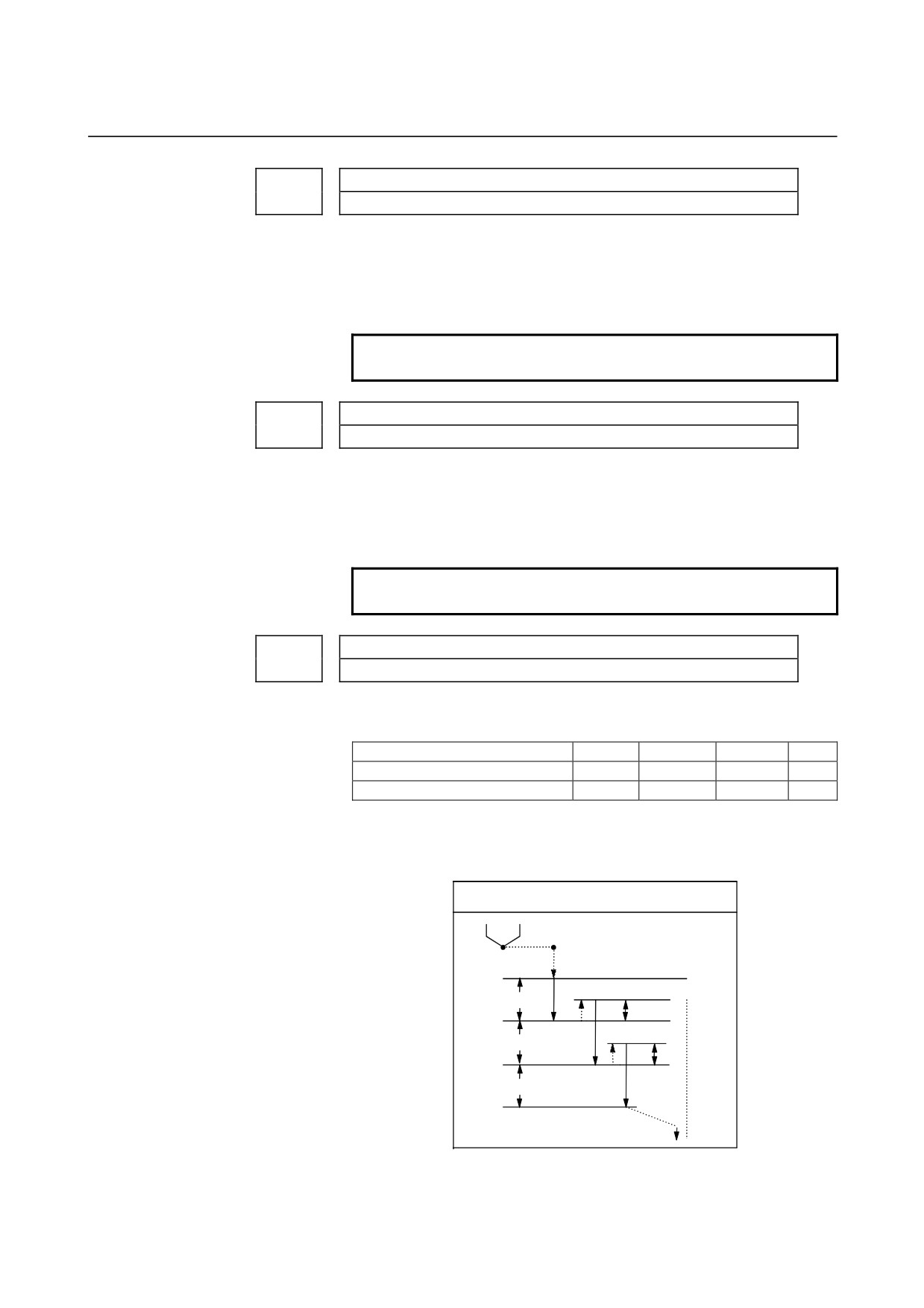
For M series this parameter sets the return value in high-speed peck
drilling cycle G73 (G83 for T series).
G73 for M series
q : Depth of cut
d : Return value
R point
q
d
q
d
q
Z point
Fig.4.22.1 (a) High-speed Peck Drilling Cycle G73
- 240 -
B-64120EN/01
4.DESCRIPTION OF PARAMETERS
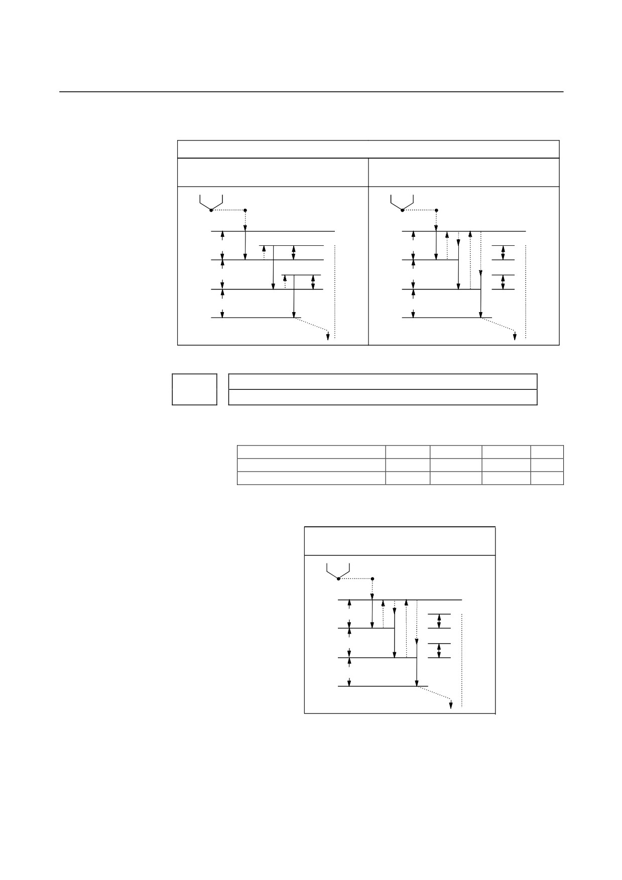
For T series this parameter sets the return or clearance value in drilling
canned cycle G83.
G83 for T series
Parameter No.5101 #2 RTR=1
Parameter No.5101 #2 RTR=0
(Peck drilling cycle)
(High speed peck drilling cycle)
q : Depth of cut
q : Depth of cut
d : Return value
d : Clearance value
R point
R point
q
q
d
d
q
q
d
d
q
q
Z point
Z point
Fig.4.22.1 (b) Drilling Canned Cycle G83
5115
Clearance of canned cycle G83
[Data type]
Word
[Unit of data]
Input increment
IS-A
IS-B
IS-C
Unit
Millimeter input
0.01
0.001
0.001
mm
Inch input
0.001
0.0001
0.0001
inch
[Valid data range]
0 to 32767
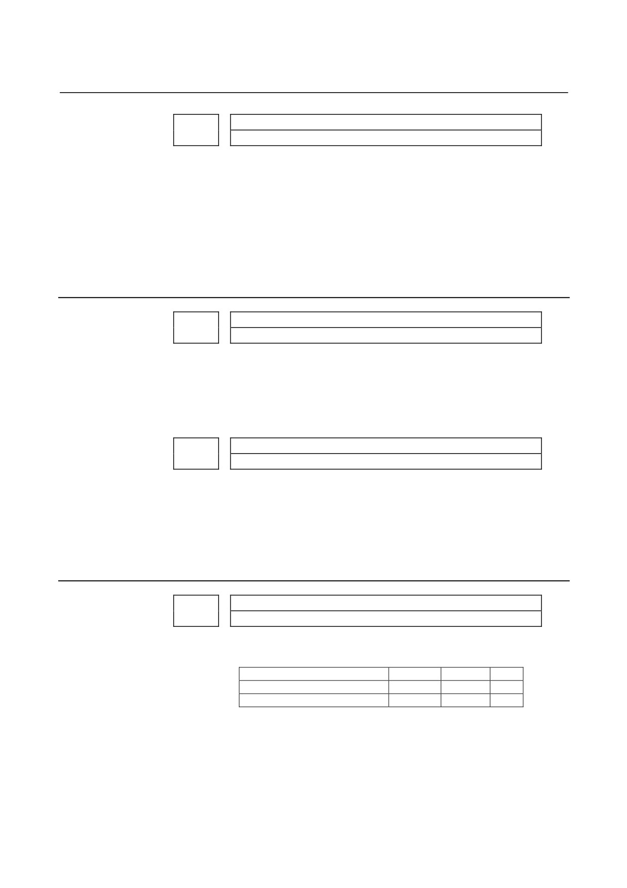
This parameter sets the clearance of peck drilling cycle G83.
G83 for 16-MC
q : Depth of cut
d : Clearance value
R point
q
d
q
d
q
Z point
Fig.4.22.1 (c) Peck drilling cycle G83
- 241 -
4.DESCRIPTION OF PARAMETERS
B-64120EN/01
Override value for retraction in boring cycle (G85, G89)
5121
[Data type] Byte
[Unit of data]
100%
[Valid data range]
0.1 to 20
Set the override value of retraction in a boring cycle.
If 20 or a greater value is specified in this parameter, the override is
set to 2000%. If 0 is specified, this parameter becomes invalid, and the
retraction speed becomes two times the cutting speed.
4.22.2 Parameter of Thread Cutting Cycle
Chamfering distance in the thread cutting cycles G76 and G92
5130
[Data type] Byte
[Unit of data]
0.1 pitch
[Valid data range]
0 to 127
This parameter sets the chamfering in the thread cutting cycles G76
and G92.
Chamfering angle in threading cycle
5131
[Data type] Byte
[Unit of data]
1 deg
[Valid data range]
1 to 89
Set a chamfering angle in a threading cycle.
4.22.3 Parameter of Multiple Repetitive Canned Cycle
Depth of cut in multiple repetitive canned cycles G71 and G72
5132
[Data type]
2-word
[Unit of data]
Input increment
IS-B
IS-C
Unit
Millimeter input
0.001
0.001
mm
Inch input
0.0001
0.0001
inch
[Valid data range]
0 to 99999999
This parameter sets the depth of cut in multiple repetitive canned
cycles G71 and G72.
- 242 -
B-64120EN/01
4.DESCRIPTION OF PARAMETERS
Escape in multiple repetitive canned cycles G71 and G72.
5133
[Data type]
2-word
[Unit of data]
Input increment
IS-B
IS-C
Unit
Millimeter input
0.001
0.001
mm
Inch input
0.0001
0.0001
inch
[Valid data range]
0 to 99999999
This parameter sets the escape in multiple repetitive canned cycle G71
and G72.
Escape in multiple repetitive canned cycle G73 in X-axis direction
5135
Escape in multiple repetitive canned cycle G73 in Z-axis direction
5136
[Data type]
2-word
[Unit of data]
Input increment
IS-B
IS-C
Unit
Millimeter input
0.001
0.001
mm
Inch input
0.0001
0.0001
inch
[Valid data range]
-99999999 to 99999999
This parameter sets the escape in multiple repetitive canned cycle G73
of an X, then Z axis.
Division count in multiple repetitive canned cycle G73
5137
[Data type]
2-word
[Unit of data]
Cycle
[Valid data range]
1 to 99999999
This parameter sets the division count in multiple repetitive canned
cycle G73.
Return in multiple canned cycles G74 and G75
5139
[Data type]
2-word
[Unit of data]
Input increment
IS-B
IS-C
Unit
Millimeter input
0.001
0.001
mm
Inch input
0.0001
0.0001
inch
[Valid data range]
0 to 99999999
This parameter sets the return in multiple repetitive canned
cycles G74 and G75.
- 243 -
4.DESCRIPTION OF PARAMETERS
B-64120EN/01
Minimum depth of cut in the multiple repetitive canned cycle G76
5140
[Data type]
2-word
[Unit of data]
Input increment
IS-B
IS-C
Unit
Millimeter input
0.001
0.0001
mm
Inch input
0.0001
0.00001
inch
[Valid data range]
0 to 99999999
This parameter sets the minimum depth of cut in the multiple
repetitive canned cycle G76.
Finishing allowance in the multiple repetitive canned cycle G76
5141
[Data type]
2-word
[Unit of data]
Input increment
IS-B
IS-C
Unit
Millimeter input
0.001
0.0001
mm
Inch input
0.0001
0.00001
inch
[Valid data range]
1 to 99999999
This parameter sets the finishing allowance in multiple repetitive
canned cycle G76.
Repetition count of final finishing in multiple repetitive canned cycle G76
5142
[Data type]
2-word
[Unit of data]
Cycle
[Valid data range]
1 to 99999999
This parameter sets the repetition count in multiple repetitive canned
cycle G76.
Tool nose angle in multiple repetitive canned cycle G76
5143
[Data type]
2-word
[Unit of data]
Degree
[Valid data range]
When FS10/11 format is used: 0 to 120
When FS10/11 format is not used: 0, 29, 30, 55, 60, 80
This parameter sets the tool nose angle in multiple repetitive canned
cycle G76.
- 244 -
B-64120EN/01
4.DESCRIPTION OF PARAMETERS
The amount of retraction from the crest of a pocket of type II in roughing
cycle (G71, G72)
5144
[Data type]
2-word
[Unit of data]
Input increment
IS-B
IS-C
Unit
Linear axis (input in mm)
0.001
0.0001
mm
Linear axis (input in inches)
0.0001
0.00001
inch
[Valid data range]
0 to 99999999
This parameter sets the amount of retraction from a crest to be crossed
to move to the next pocket to be roughed after roughing of a pocket of
type II in roughing cycle (G71 or G72) ends.
If this parameter is set to 0, 2000 (IS-B) or 20000 (IS-C) is assumed
by default. When 0 is set for IS-B metric input, for example, the
amount of retraction is assumed to be 1.0 mm if a radius is specified
(bit 3 (DIA) of parameter No. 1006 = 0) or 2.0 mm if a diameter is
specified (bit 3 (DIA) of parameter No. 1006 = 1).
5150
Inertial running distance in a canned cycle for high-speed positioning and
drilling
[Data type]
2-word
[Unit of data]
Input increment
IS-A
IS-B
IS-C
Unit
Millimeter input
0.01
0.001
0.0001
mm
Inch input
0.001
0.0001
0.00001
inch
[Valid data range]
0 to 99999999
This parameter sets the distance of inertial running in a canned cycle
for high-speed positioning and drilling.
5151
Rapid traverse deceleration ratio for overlap between rapid traverse blocks
in a canned cycle for high-speed positioning and drilling
[Data type]
Byte
[Unit of data]
%
[Valid data range]
0 to 100
This parameter sets the rapid traverse deceleration ratio for an overlap
between rapid traverse blocks in a canned cycle for high-speed
positioning and drilling. In the cycle, the setting of this parameter is
valid for all axes.
NOTE
In a canned cycle for high-speed positioning and
drilling, a rapid traverse overlap is applied even
when bit 4 (RTO) of parameter No. 1601 is set to 0.
To disable the rapid traverse overlap, set this
parameter to 0.
- 245 -
4.DESCRIPTION OF PARAMETERS
B-64120EN/01
4.22.4
Parameters of Peck Drilling Cycle of a Small Diameter
#7
#6
#5
#4
#3
#2
#1
#0
CYM
5160
CYM
NOL
OLS
[Data type]
Bit
OLS
When an overload torque signal is received in a peck drilling cycle of
a small diameter, the feed and spindle speed are
0 : Not changed.
1 : Changed.
NOL
When the depth of cut per action is satisfied although no overload
torque signal is received in a peck drilling cycle of a small diameter,
the feed and spindle speed are:
0 : Not changed.
1 : Changed.
CYM
When a subprogram call
(M98) and another NC command are
specified in the same block in a canned cycle mode:
0 : No alarm is issued.
1 : AN alarm is issued. (P/S alarm 5329)
#7
#6
#5
#4
#3
#2
#1
#0
RLV
PKG
5161
[Data type]
Bit
PKG
Method for specifying a high-speed peck drilling cycle and a peck
drilling cycle
0 : G83 or G87 is used, and a high-speed peck drilling or peck
drilling cycle is selected by bit 2 (RTR) of parameter No. 5101.
1 : A specification is added to the G83 or G87 command so that a
high-speed peck drilling cycle can be specified using G83.5 or
G87.5 and that a peck drilling cycle can be specified using G83.6
or G87.6.
NOTE
When the FS10/11 format is used (when bit 1
(FCV) of parameter No. 0001 is set to 1), this
parameter is invalid.
RLV
For G code system A, the return operation in a drilling canned cycle
performs:
0 : A return to the initial level.
1 : A return to the level of the R point.
NOTE
For G code systems B and C, a selection is made
using G codes.
G98: Return to the initial level
G99: Return to the level of the R point
- 246 -

B-64120EN/01
4.DESCRIPTION OF PARAMETERS
5163
M code that specifies the peck drilling cycle mode of a small diameter
[Data type]
2-word
[Valid data range]
1 to 99999999
This parameter sets an M code that specifies the peck drilling
cycle mode of a small diameter.
5164
Percentage of the spindle speed to be changed when the tool is retracted
after an overload torque signal is received
[Data type]
Byte
[Unit of data]
%
[Valid data range]
1 to 255
This parameter sets the percentage of the spindle speed to be changed
when the tool is retracted because the overload torque signal is
received in a peck drilling cycle of a small diameter.
S2 = S1 × d1 ÷ 100
S1: Spindle speed to be changed
S2: Spindle speed changed
d1 is set as a percentage.
5165
Percentage of the spindle speed to be changed when the tool is retracted
without an overload torque signal received
[Data type]
Byte
[Unit of data]
%
[Valid data range]
1 to 255
This parameter sets the percentage of the spindle speed to be changed
when the tool is retracted without the overload torque signal received
in a peck drilling cycle of a small diameter.
S2 = S1 × d2 ÷ 100
S1: Spindle speed to be changed
S2: Spindle speed changed
d2 is set as a percentage.
- 247 -

4.DESCRIPTION OF PARAMETERS
B-64120EN/01
5166
Percentage of cutting feedrate to be changed when the tool is retracted after
an overload torque signal is received
[Data type]
Byte
[Unit of data]
%
[Valid data range]
1 to 255
This parameter sets the percentage of the cutting feedrate to be
changed when the tool is retracted because the overload torque signal
is received in a peck drilling cycle of a small diameter.
F2 = F1 × b1 ÷ 100
F1: Cutting feedrate to be changed
F2: Changed cutting feedrate
b1 is set as a percentage.
5167
Percentage of the cutting feedrate to be changed when the tool is retracted
without an overload torque signal received
[Data type]
Byte
[Unit of data]
%
[Valid data range]
1 to 255
This parameter sets the percentage of the cutting feedrate to be
changed when the tool is retracted without the overload torque signal
received in a peck drilling cycle of a small diameter.
F2 = F1 × b2 ÷ 100
F1: Cutting feedrate to be changed
F2: Changed cutting feedrate
b2 is set as a percentage.
5168
Lower limit of the percentage of the cutting feedrate in a peck drilling cycle
of a small diameter
[Data type]
Byte
[Unit of data]
%
[Valid data range]
0 to 255
This parameter sets the lower limit of the percentage of the cutting
feedrate changed repeatedly in a peck drilling cycle of a small
diameter to the specified cutting feedrate.
FL = F × b3 ÷ 100
F: Specified cutting feedrate
FL: Changed cutting feedrate
Set b3 as a percentage.
- 248 -
B-64120EN/01
4.DESCRIPTION OF PARAMETERS
5170
Number of the macro variable to which the total number of retractions during
cutting is output
[Data type] Word
[Valid data range]
100 to 149
This parameter sets the number of the macro variable to which the
total number of times the tool is retracted during cutting in a peck
drilling cycle mode of a small diameter is output.
NOTE
The total number cannot be output to common
variables 500 to 531.
5171
Number of the macro variable to which the total umber of retractions
because of an overload signal is output
[Data type] Word
[Valid data range]
100 to 149
This parameter sets the common variable number of the custom macro
to which the number of times the tool is retracted after the overload
signal is received during cutting in a peck drilling cycle mode of a
small diameter is output.
NOTE
The total number cannot be output to common
variables 500 to 531.
5172
Speed of retraction to point R when no address I is issued
[Data type] Word
[Unit of data] mm/min
[Valid data range]
0 to 400
This parameter sets the speed of retraction to point R when no address
I is issued in a peck drilling cycle of a small diameter.
5173
Speed of advancing to the position just before the bottom of a hole when no
address I is issued
[Data type] Word
[Unit of data] mm/min
[Valid data range]
0 to 400
This parameter sets the speed of advancing to the position just before
the bottom of a previously machined hole when no address I is issued
in a peck drilling cycle of a small diameter.
- 249 -

4.DESCRIPTION OF PARAMETERS
B-64120EN/01
5174
Clearance in a peck drilling cycle of a small diameter
[Data type] Word
[Unit of data]
Input increment
IS-A
IS-B
IS-C
Unit
Linear axis (input in mm)
0.01
0.001
0.0001
mm
Linear axis (input in inches)
0.001
0.0001
0.00001
inch
[Valid data range]
0 to 32767
This parameter sets the clearance in a peck drilling cycle of a small
diameter.
- 250 -

B-64120EN/01
4.DESCRIPTION OF PARAMETERS
4.23
PARAMETERS OF RIGID TAPPING
#7
#6
#5
#4
#3
#2
#1
#0
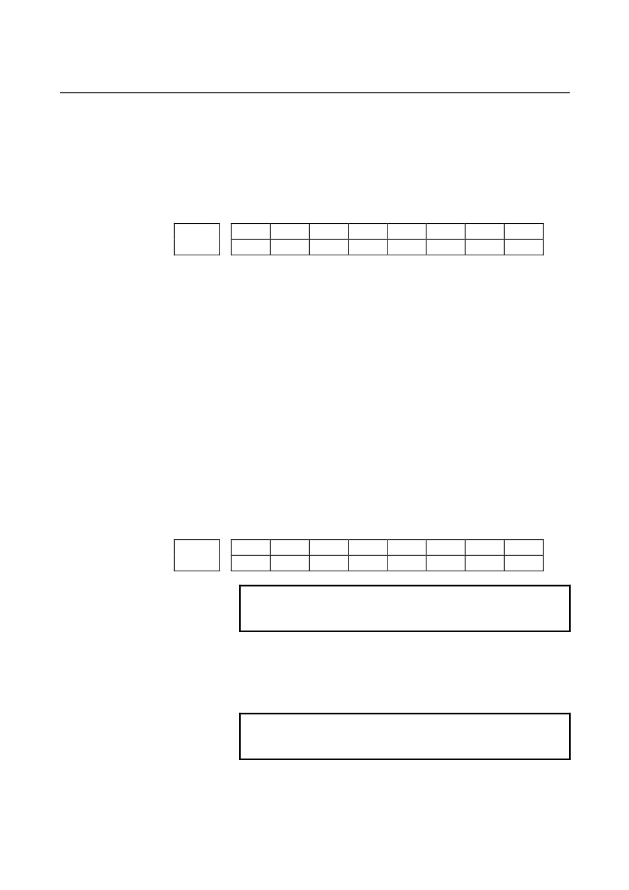
SRS
FHD
DOV
SIG
CRG
VGR
G84
5200
FHD
PCP
DOV
SIG
CRG
VGR
G84
[Data type]
Bit
G84
Method for specifying rigid tapping
0 : An M code specifying the rigid tapping mode is specified prior to
the issue of the G84
(or G74) command.
(See parameter
No.5210).
1 : An M code specifying the rigid tapping mode is not used.
(G84
cannot be used as a G code for the tapping cycle; G74 cannot be
used for the reverse tapping cycle.)
VGR
Any gear ratio between spindle and position coder in rigid tapping
0 : Not used
(The gear ratio is set in parameter No.3706.)
1 : Used
(The gear ratio is set by parameters Nos. 5221 through
5224 and 5231 through 5234.)
NOTE
For serial spindles, set this parameter to 0 when
using the DMR function for position coder signals
on the spindle side.
CRG
Rigid mode when a rigid mode cancel command is specified (G80,
G01 group G code, reset, etc.)
0 : Canceled after rigid tapping signal RGTAP <G061#0> is set to
"0".
1 : Canceled before rigid tapping signal RGTAP <G061#0> is set to
"0".
SIG
When gears are changed for rigid tapping, the use of SIND <G032 and
G033> is
0 : Not permitted.
1 : Permitted.
DOV
Override during extraction in rigid tapping
0 : Invalidated
1 : Validated (The override value is set in parameter No.5211 (M/T)
or No.5381(M).)
PCP
Tapping or rigid tapping
0 : Used as a high-speed peck tapping cycle
1 : Not used as a high-speed peck tapping cycle
For the T series, this parameter is valid when bit 6 (PCT) of parameter
No. 5104 is set to 1.
According to the setting of this parameter, also set parameter No.
5213.
FHD
Feed hold and single block in rigid tapping
0 : Invalidated
1 : Validated
SRS
To select a spindle used for rigid tapping in multi-spindle
control:
- 251 -
4.DESCRIPTION OF PARAMETERS
B-64120EN/01
0 : The spindle selection signals SWS1 and SWS2 (bits 0 and 1 of
G027) are used. (These signals are used also for multi-spindle
control.)
1 : The rigid tapping spindle selection signals RGTSP1 and
RGTSP2 (bits 4 and 5 of G061) are used.
(These signals are
provided expressly for rigid tapping.)
#7
#6
#5
#4
#3
#2
#1
#0
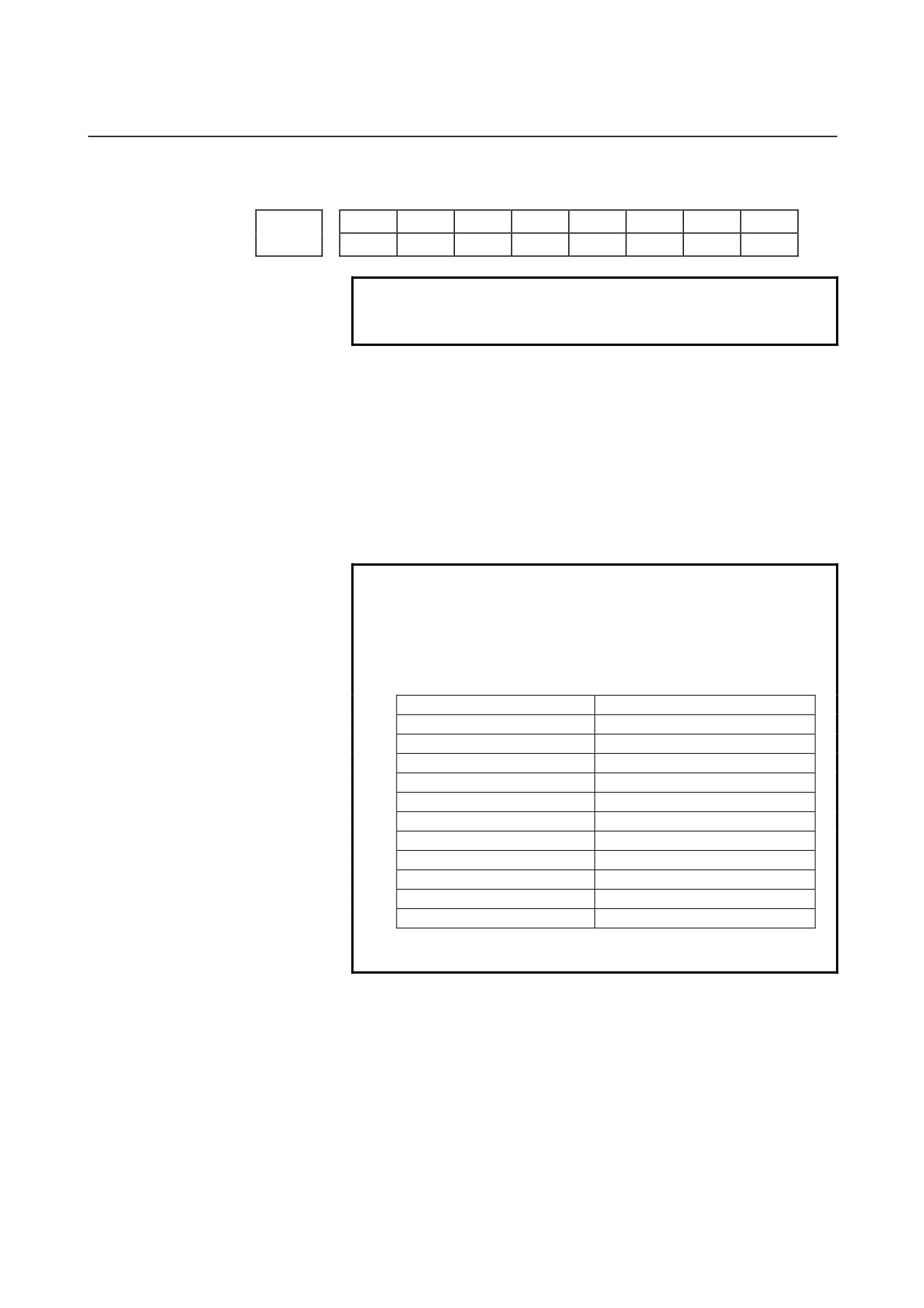
OV3
OVU
TDR
5201
OV3
OVU
TDR
NIZ
[Data type]
Bit
NIZ
Smoothing in rigid tapping is:
0 : Not performed.
1 : Performed.
TDR
Cutting time constant in rigid tapping
0 : Uses a same parameter during cutting and extraction (Parameter
Nos. 5261 through 5264)
1 : Not use a same parameter during cutting and extraction
Parameter Nos. 5261 to 5264: Time constant during cutting
Parameter Nos. 5271 to 5274: Time constant during extraction
OVU
The increment unit of the override parameter (No.5211 (M/T) or
No.5381 (M)) for tool rigid tapping extraction is:
0 :
1%
1 :
10%
OV3
The spindle speed for tool extraction is specified by program.
The
tool extraction function based on this spindle speed is:
0 : Disabled.
1 : Enabled.
#7
#6
#5
#4
#3
#2
#1
#0
ORI
5202
RG3
ORI
NOTE
When this parameter is set, the power must be
turned off before operation is continued.
[Data type]
Bit
ORI
When rigid tapping is started:
0 : Spindle orientation is not performed.
1 : Spindle orientation is performed.
NOTE
This parameter can be used only for a serial
spindle.
RG3
A rigid tapping return operation is specified:
0 : With input signal RTNT <G062#6>.
1 : With one-shot G code G30.
- 252 -

B-64120EN/01
4.DESCRIPTION OF PARAMETERS
#7
#6
#5
#4
#3
#2
#1
#0
OVS
RGS
5203
RBL
OVS
RFF
[Data type]
Bit
REF
Feed forward during movement from the initial point to point R in
rigid tapping is:
0 : Disabled.
1 : Enabled.
When this parameter is set, the following function is also enabled:
•
When rigid tapping is specified in advanced preview control
mode, the system automatically exits from advanced preview
control mode and executes rigid tapping. After termination of
rigid tapping, the system automatically returns to look-ahead
control mode.
RGS
When bit 0 (MIF) of parameter No. 1403 is set to 1 and rigid tapping
is specified in feed-per-minute mode, the spindle speed becomes:
0 :
1/1000 of the specified speed.
1 :
1/1 of the specified speed.
OVS
In rigid tapping, override by the feedrate override signal and
invalidation of override by the override cancel signal is:
0 : Disabled.
1 : Enabled.
Setting this parameter enables override by the feedrate override signal
<G012> to be applied for rigid tapping operation
(cutting and
extraction) in rigid tapping.
The spindle speed override is fixed to 100%, but override is also
applied to the spindle speed in synchronization with the feedrate along
the tapping axis by feedrate override.
The override cancel signal OVC <bit 4 of G006> also becomes
available.
NOTE
1 When this parameter is set to override the feedrate,
override by parameters (see parameters Nos. 5211
(T/M) and 5381 (M)) is disabled.
2 Regardless of whether this parameter is set, when
feedrate override is disabled by the override cancel
signal OVC <bit 4 of G006>, override by
parameters (see parameters Nos. 5211 (T/M) and
5381 (M)) is enabled.
RBL
As acceleration/deceleration for rigid tapping cutting feed:
0 : Linear acceleration/deceleration is used.
1 : Bell-shaped acceleration/deceleration is used.
NOTE
The bell-shaped acceleration/deceleration option
for rigid tapping is required.
- 253 -
4.DESCRIPTION OF PARAMETERS
B-64120EN/01
#7
#6
#5
#4
#3
#2
#1
#0
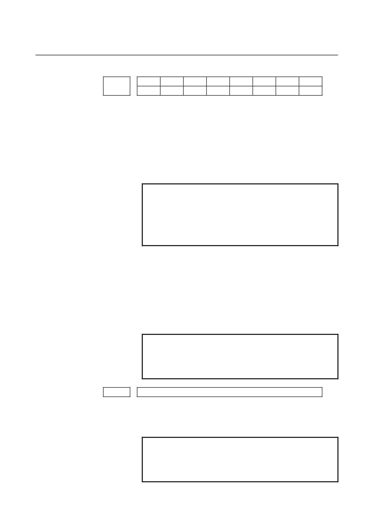
SPR
DGN
5204
DGN
NOTE
When this parameter is set, the power must be
turned off before operation is continued.
[Data type]
Bit
DGN
On the diagnosis screen:
0 : A rigid tapping synchronization error is displayed. (Nos. 455 to
457)
1 : An error difference between the spindle and tapping axis
is
displayed. (Nos. 452 and 453)
SPR
In rigid tapping, the parameters are:
0 : Not changed on a spindle-by-spindle basis.
1 : Changed on a spindle-by-spindle basis.
NOTE
1 When switching between the rigid tapping
parameters on a spindle-by-spindle basis in rigid
tapping using the second serial spindle, set this
parameter to 1. The following parameters are
supported for each spindle:
First spindle
Second spindle (2-stage gear)
No.5214
No.5215
No.5221 to No.5224
No.5225, No.5226
No.5231 to No.5234
No.5235, No.5236
No.5241 to No.5244
No.5245, No.5246
No.5261 to No.5264
No.5265, No.5266
No.5271 to No.5274
No.5335, No.5336
No.5280
No.5341
No.5281 to No.5284
No.5342, No.5343
No.5300, No.5301
No.5302, No.5303
No.5310 to No.5314
No.5350 to No.5353
No.5321 to No.5324
No.5325, No.5326
2 For rigid tapping using the second serial spindle,
the multispindle control option is required.
- 254 -
B-64120EN/01
4.DESCRIPTION OF PARAMETERS
#7
#6
#5
#4
#3
#2
#1
#0
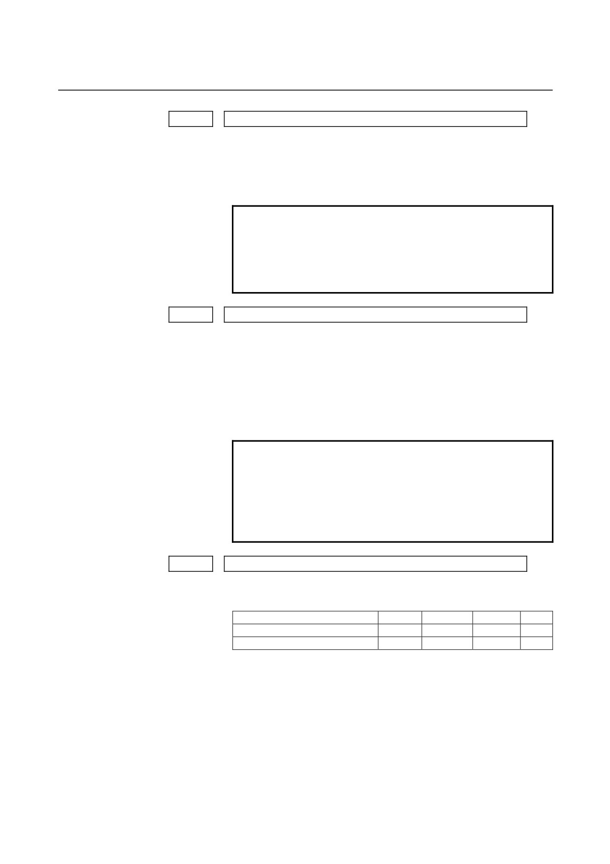
REF
PKD
RCK
5205
REF
NRV
RCK
[Data type]
Bit
RCK
In rigid tapping, an excessive error during movement/at stop is:
0 : Checked regardless of whether mode is cutting (tapping) or rapid
traverse.
1 : Checked only in cutting (tapping) mode.
NRV
For the rigid tapping function, the spindle returns back from the
bottom of a hole with:
0 : Rotating opposite to the drilling direction
1 : Rotating in the drilling direction (special purpose)
CAUTION
This parameter is intended for special uses only.
When rigid tapping is performed, therefore, this
parameter must not be set.
If rigid tapping is performed with this parameter set,
a tapping tool, workpiece, or machine may be
damaged.
PKD
For rigid peck tapping, diagnostic number
457 (maximum rigid
tapping synchronization error) indicates:
0 : A value per tap operation.
1 : A total value until the hole bottom is reached.
REF
Fine acceleration/deceleration during rigid tapping is:
0 : Disabled.
1 : Enabled.
To use the spindle fine acceleration/deceleration (FAD) function, set
1.
NOTE
When fine acceleration/deceleration is used, fine
acceleration/deceleration settings for the spindle
and servo system must be made in addition to the
setting of this parameter.
5210
Rigid tapping mode specification M code
[Data type]
Byte
[Valid data range]
0 to 255
This parameter sets an M code that specifies the rigid tapping mode.
NOTE
1 A setting value of 0 is assumed to be 29 (M29).
2 To use an M code whose number is greater than
256, Specify the code number with parameter
No.5212.
- 255 -
4.DESCRIPTION OF PARAMETERS
B-64120EN/01
5211
Override value during rigid tapping extraction
[Data type]
Byte
[Unit of data]
1 % or 10 %
[Valid data range]
0 to 200
The parameter sets the override value during rigid tapping extraction.
NOTE
The override value is valid when DOV in parameter
No.5200 #4 is "1".
When OVU (bit 3 of parameter No.5201) is 1, the
unit of set data is 10%. An override of up to 200%
can be applied to extraction.
5212
M code that specifies a rigid tapping mode
[Data type]
2-word
[Unit of data]
Integer
[Valid data range]
0 to 65535
This parameter sets the M code that specifies the rigid tapping mode.
The M code that specifies the rigid tapping mode is usually set by
parameter 5210. To use an M code whose number is greater than 256,
specify the code number with parameter 5212.
NOTE
If the setting of this parameter is 0, the M code
specifying the rigid tapping mode is determined by
the setting of parameter 5210. Otherwise, it is
determined by the setting of parameter 5212. The
setting of parameter 5212 must always be within
the above valid range.
5213
Return or clearance in peck tapping cycle
[Data type]
Word
[Unit of data]
Input increment
IS-A
IS-B
IS-C
Unit
Millimeter input
0.01
0.001
0.001
mm
Inch input
0.001
0.0001
0.0001
inch
[Valid data range]
0 to 32767
This parameter sets the return or clearance in the peck tapping cycle.
- 256 -
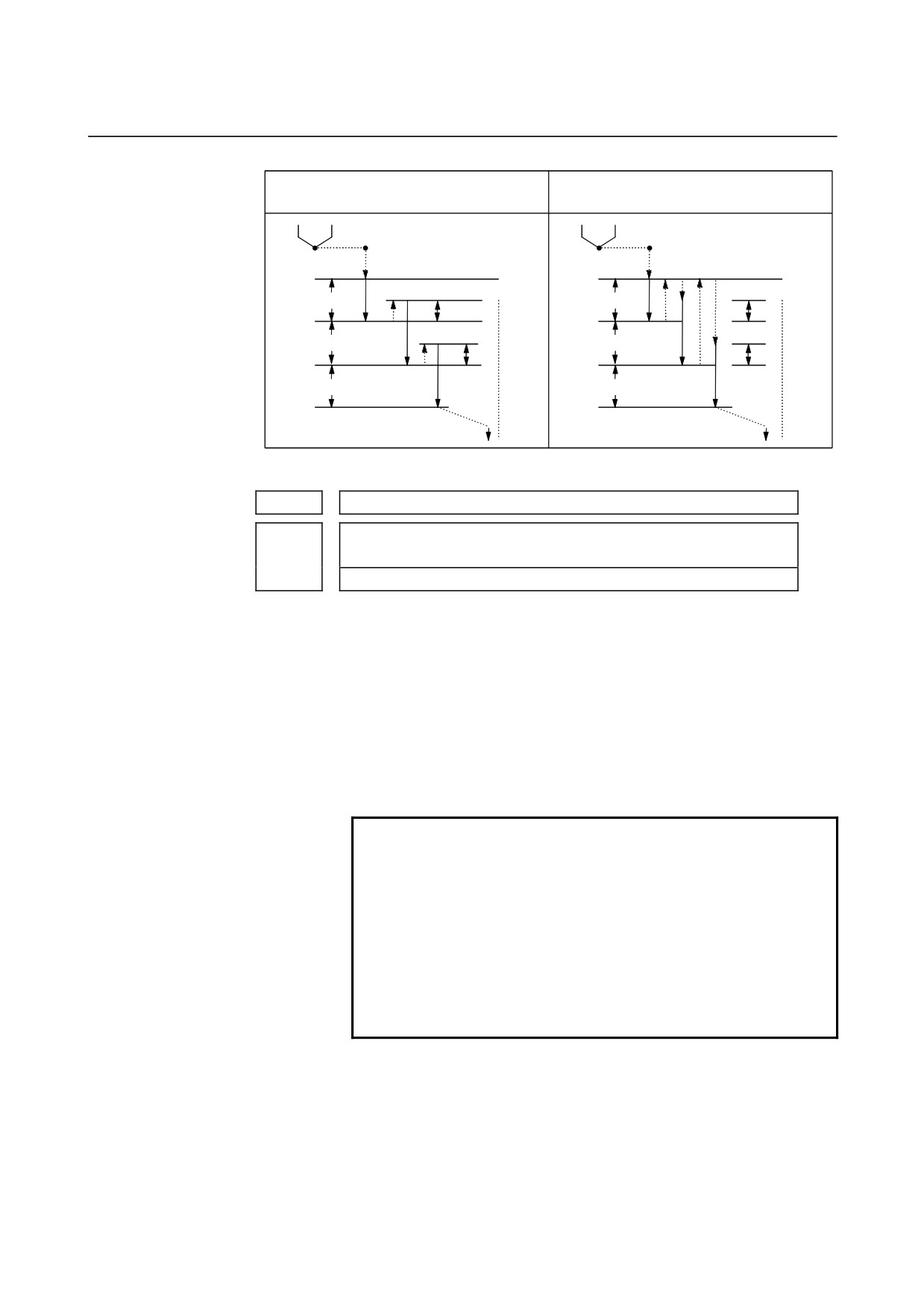
B-64120EN/01
4.DESCRIPTION OF PARAMETERS
Parameter No.5200#5 PCP=0
Parameter No.5200#5 PCP=1
(Return in peck tapping cycle)
(Clearance in peck tapping cycle)
q : Depth of cut
q : Depth of cut
d : Return value
d : Clearance value
R point
R point
q
q
d
d
q
q
d
d
q
q
Z point
Z point
Fig.4.23 (a) High-speed Peck Drilling and Peck Drilling Cycles
5214
Setting of an allowable rigid tapping synchronization error range
Setting of an allowable rigid tapping synchronization error range for the
5215
second spindle
[Data type] Word
[Unit of data] Detection unit (1/4096rev)
[Valid data range]
0 to 32767
Each of these parameters is used to set an allowable synchronization
error range between a spindle used for rigid tapping and the tapping
axis.
If the value set with each parameter is exceeded, rigid tapping alarm
No.741 (excessive error during movement) is issued. When 0 is set, a
synchronization error check is not made.
NOTE
When rigid tapping is performed using the second
spindle
• When the SPR parameter (bit 1 of parameter
No.5204) is set to 0, the setting of parameter
No.5214 is applied to the second spindle, as
well as to the first spindle.
• When the SPR parameter (bit 1 of parameter
No.5204) is set to 1, the settings of parameter
No.5215 is applied to the second spindle.
- 257 -

4.DESCRIPTION OF PARAMETERS
B-64120EN/01
5221
Number of spindle gear teeth (first-stage gear)
5222
Number of spindle gear teeth (second-stage gear)
5223
Number of spindle gear teeth (third-stage gear)
Number of spindle gear teeth (fourth-stage gear)
5224
Number of second spindle gear teeth (first-stage gear)
5225
Number of second spindle gear teeth (second-stage gear)
5226
[Data type]
Word
[Valid data range]
1 to 32767
When an arbitrary gear ratio is used in rigid tapping, each of these
parameters sets the number of teeth of each spindle gear.
NOTE
1 These parameters are enabled when the VGR
parameter (bit 1 of parameter No.5200) is set to 1.
2 When a position coder is attached to the spindle,
set the same value for all of parameters No.5221
through No.5224.
3 When the DMR function of the position coder signal
is used with a serial spindle, set the VGR
parameter (bit 1 of parameter No.5200) to 0, and
set these parameters to 0.
4 When rigid tapping is performed using the second
spindle
• When the SPR parameter (bit 1 of parameter
No.5204) is set to 0, the settings of parameters
No.5221 and No.5222 are applied to the second
spindle, as well as to the first spindle.
• When the SPR parameter (bit 1 of parameter
No.5204) is set to 1, the settings of parameters
No.5225 and No.5226 are applied to the second
spindle.
- 258 -
B-64120EN/01
4.DESCRIPTION OF PARAMETERS
5231
Number of position coder gear teeth (first-stage gear)
5232
Number of position coder gear teeth (second-stage gear)
5233
Number of position coder gear teeth (third-stage gear)
Number of position coder gear teeth (fourth-stage gear)
5234
Number of position coder gear teeth for the second spindle (first-stage gear)
5235
Number of position coder gear teeth for the second spindle (second-stage
5236
gear)
[Data type]
Word
[Valid data range]
1 to 32767
When an arbitrary gear ratio is used in rigid tapping, each of these
parameters sets the number of teeth of each position coder gear.
NOTE
1
These parameters are enabled when the VGR
parameter (bit 1 of parameter No.5200) is set to 1.
When a position coder is attached to the spindle,
set the same value for all of parameters No.5231
through No.5234.
When a spindle motor with a built-in position coder
is used, a position coder with a resolution of 2048
pulses/rev may be used. In such a case, set the
actual number of teeth, multiplied by 2 (for
conversion to 4096 pulses/rev).
2
When the DMR function of the position coder signal
is used with a serial spindle, set the VGR
parameter (bit 1 of parameter No.5200) to 0, and
set these parameters to 0.
3
When rigid tapping is performed using the second
spindle
• When the SPR parameter (bit 1 of parameter
No.5204) is set to 0, the settings of parameters
No.5231 and No.5232 are applied to the second
spindle, as well as to the first spindle.
• When the SPR parameter (bit 1 of parameter
No.5204) is set to 1, the settings of parameters
No.5235 and No.5236 are applied to the second
spindle.
- 259 -
4.DESCRIPTION OF PARAMETERS
B-64120EN/01
5241
Maximum spindle speed in rigid tapping (first-stage gear)
5242
Maximum spindle speed in rigid tapping (second-stage gear)
5243
Maximum spindle speed in rigid tapping (third-stage gear)
Maximum spindle speed in rigid tapping (fourth-stage gear)
5244
Maximum spindle speed in rigid tapping using the second spindle
5245
(first-stage gear)
Maximum spindle speed in rigid tapping using the second spindle
5246
(second-stage gear)
[Data type]
2-word
[Unit of data]
min-1
[Valid data range]
The setting range is determined according to the spindle to position
coder gear ratio as follows:
Spindle : Position coder
Setting range
1 : 1
0 to 7400
1 : 2
0 to 9999
1 : 4
0 to 9999
1 : 8
0 to 9999
Each of these parameters is used to set a maximum spindle speed for
each gear in rigid tapping.
NOTE
1 For the M series, set the same value for both
parameter No.5241 and parameter No.5243 for a
one-stage gear system. For a two-stage gear
system, set the value specified for parameter No.
5241 or 5242, whichever is greater, for parameter
No. 5243. Otherwise, P/S alarm No.200 will be
issued.
2 When rigid tapping is performed using the second
spindle
• When the SPR parameter (bit 1 of parameter
No.5204) is set to 0, the settings of parameters
No.5241 and No.5242 are applied to the second
spindle, as well as to the first spindle.
• When the SPR parameter (bit 1 of parameter
No.5204) is set to 1, the settings of parameters
No.5245 and No.5246 are applied to the second
spindle.
- 260 -
B-64120EN/01
4.DESCRIPTION OF PARAMETERS
5261
Linear acceleration/deceleration time constant for the spindle and tapping
axis (first-stage gear)
5262
Linear acceleration/deceleration time constant for the spindle and tapping
axis (second-stage gear)
5263
Linear acceleration/deceleration time constant for the spindle and tapping
axis (third-stage gear)
Linear acceleration/deceleration time constant for the spindle and tapping
5264
axis (fourth-stage gear)
Linear acceleration/deceleration time constant for the second spindle and
5265
tapping axis (first-stage gear)
Linear acceleration/deceleration time constant for the second spindle and
5266
tapping axis (second-stage gear)
[Data type] Word
[Unit of data] ms
[Valid data range]
0 to 4000
Each of these parameters is used to set a linear
acceleration/deceleration time constant for the spindle of each gear
and the tapping axis in rigid tapping.
Set the period required to reach each maximum spindle speed
(parameters No.5241 through No.5248). The set time constant,
multiplied by the ratio of a specified S value to a maximum spindle
speed, is actually used as a time constant.
NOTE
When rigid tapping is performed using the second
spindle
• When the SPR parameter (bit 1 of parameter
No.5204) is set to 0, the settings of parameters
No.5261 and No.5262 are applied to the second
spindle, as well as to the first spindle.
• When the SPR parameter (bit 1 of parameter
No.5204) is set to 1, the settings of parameters
No.5265 and No.5266 are applied to the second
spindle.
- 261 -