FANUC Series 90-30 PLC. Installation and Hardware Manual (GFK-0356P) - page 8
Chapter
State Logic Products
9
State Logic Overview
State Logic, unlike other Series 90-30 PLC systems, does not use ladder logic type
instructions. Instead, it uses ”Natural Language” programming instructions. For
example, to program a rung of logic that turns on a motor at a specific time in a State
Logic system, you could create a statement, “If hour is past 8 AM, start the
exhaust_system.” This type of programming instruction cannot be handled currently by
standard Series 90-30 CPUs, so a State Logic CPU is required. This chapter only provides
an overview of State Logic products. For details, please see GFK-1056, Series 90-30 State
Logic Control System User’s Manual.
State Logic Products
The State Logic product line consist of just a few key hardware and software items. To
complete a State Logic system, standard Series 90-30 products are used. The primary
State Logic products are:
State Logic CPUs. There are five models: 311, 313, 323, 331, and 340.
State Logic Processor Module (IC693SLP300). This module can reside in a Series
90-30 PLC system containing a standard CPU, providing the user with both standard
ladder logic and State Logic capabilities.
Serial Communications Module (AD693CMM301). Provides two additional serial
ports for the State Logic system. Requires a 331 or 340 State Logic CPU.
ECLiPS software. Provides Natural Language programming and online debugging
functions.
OnTOP software. A debugging tool, it provides operator interface, maintenance, or
troubleshooting functions. It has all the capabilities of the ECLiPS debugging
function.
Baseplates and Power Supply, I/O, and Option Modules
The State Logic CPUs and modules work with most standard Series 90-30 baseplates,
power supplies, input and output modules (discrete and analog), and option modules.
Please see GFK-1056, Series 90-30 State Logic Control System User’s Manual, for details.
9-1
GFK-0356P
9
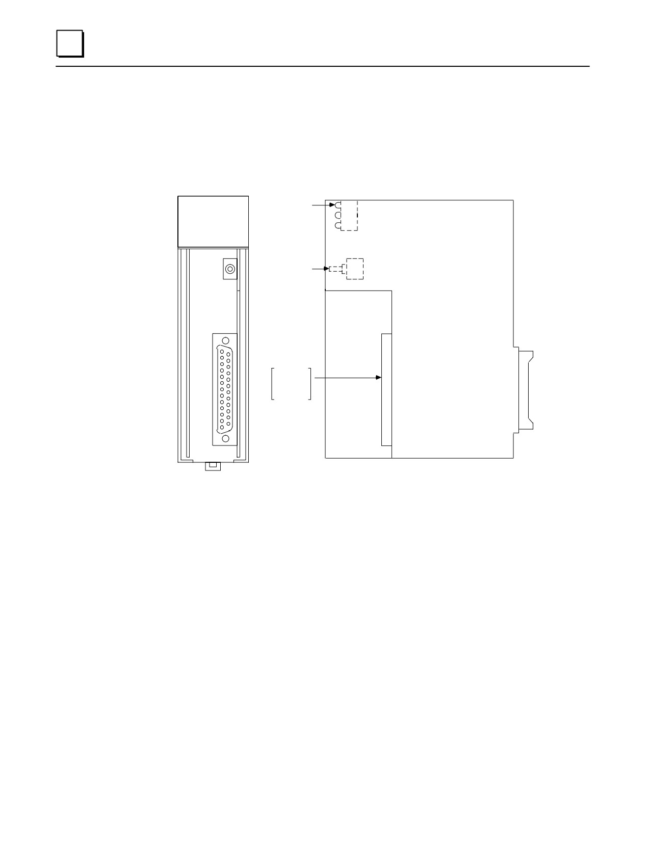
AD693CMM301 State Logic Serial Communications Module (SCM)
Description
This module provides two additional serial ports for a Series 90-30 State Logic PLC
System. A model 331 or 340 State Logic CPU is required.
a44902
OK
OK
Î
Î
RESTART
COMBINED
SERIAL PORT
PORT1
&
PORT2
Figure 9-1. AD693CMM301 State Logic Serial Communications Module
OK LED
The SCM turns on its OK LED after completing its start-up internal self test procedure.
The OK LED remains ON as long as the module is functioning properly. If the OK LED
turns OFF while power is applied to the system, turn OFF PLC power and make sure
the module is properly seated in the baseplate. Turn power back ON. If the OK LED
remains OFF when power comes back up, it indicates a probable hardware failure in the
SCM and it should be returned for repair. The other two LEDs on this module are not
used.
Reset Button
Pressing the Reset pushbutton when the OK LED is ON re-initializes the module.
However, if the OK LED is off (indicating a module failure), pressing the Reset button
will have no effect.
Serial Connector
The SCM front-mounted serial port connector provides all of the connections for the two
SCM serial ports. Separate pins on this connector are assigned for Port 1 and Port 2.
9-2
Series 90-30 PLC Installation and Hardware Manual - October 1999
GFK-0356P
9
Both ports support RS-232 standard. Only Port 2 supports the RS-485 standard. A
special WYE cable, described below, is available from GE Fanuc to separate the two port
connections on the connector.
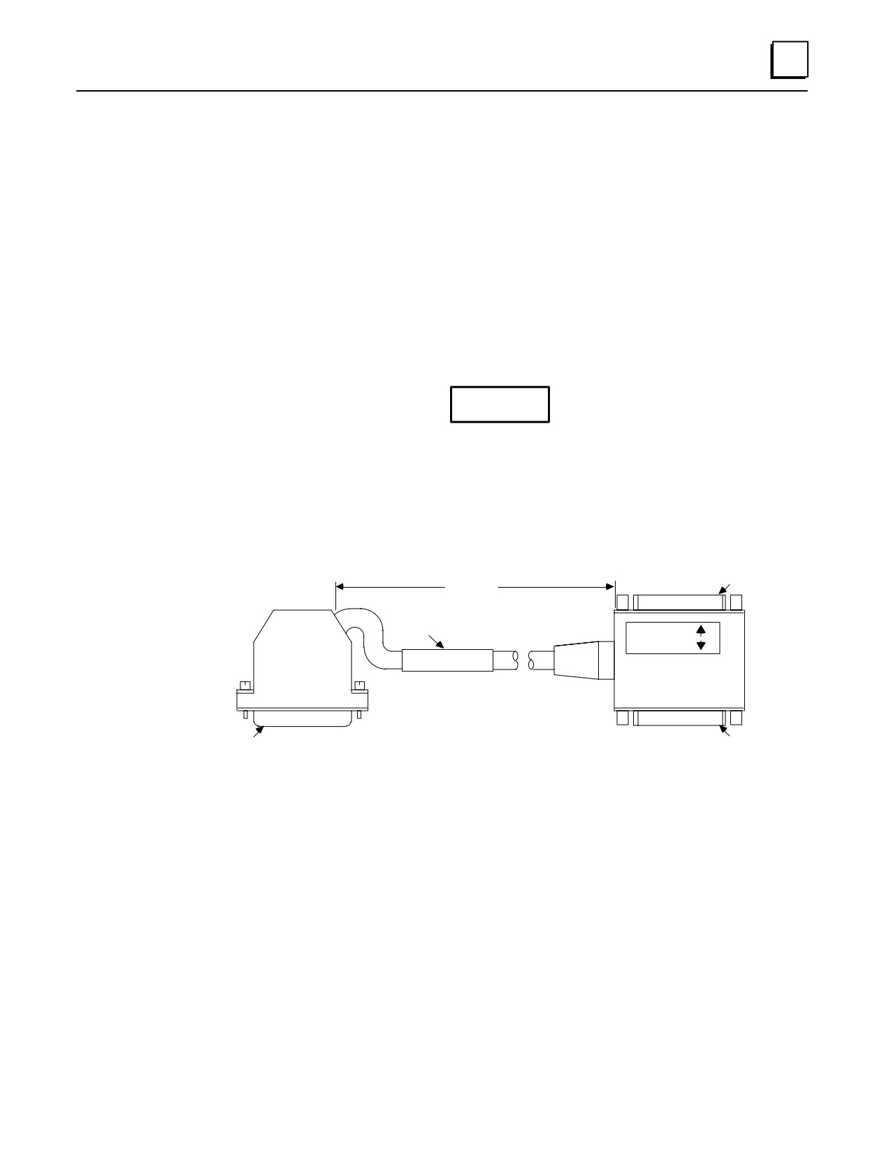
Cable Information
Cable IC693CBL305 can be used in applications that require use of both SCM serial ports.
This is a Wye-type cable that breaks out the Port 1 and Port 2 connections on the
module’s single connector to two individual connectors. A data sheet for this cable can
be found in the “Cables” chapter of this manual. (Additional SCM cable information is
found in the two documents referenced in the next section.) This cable wouldn’t be
required for applications that use only one SCM port. Also, this cable should not be
used in a multidrop network (see Caution note below).
Caution
The IC693CBL305 Wye cable should not be used with an SCM
connected to a multidrop network because it introduces signal
reflections on the network. Multidrop networks should be cabled
directly to the SCM serial connector.
a44225
RS-232
25-PIN FEMALE
CONNECTOR PIN 1
1 FOOT
(+2.0 INCH, -0 INCH)
LABEL
ÎÎ
PORT 1
PORT 2
Î
PCM COMM. CABLE
Î
IC693CBL305B
ÎÎ
RS-232
RS-232/RS-485
PIN 1
PIN 1
25-PIN MALE
25-PIN FEMALE
CONNECTOR
CONNECTOR
Figure 9-2. IC693CBL305 WYE Cable
State Logic SCM Documentation
GFK-1661 (Data Sheet), Serial Communications Module, Series 90-30 State Logic
GFK-1056, Series 90-30 State Logic Control System User’s Manual
GFK-0356P
Chapter 9 State Logic Products
9-3
9
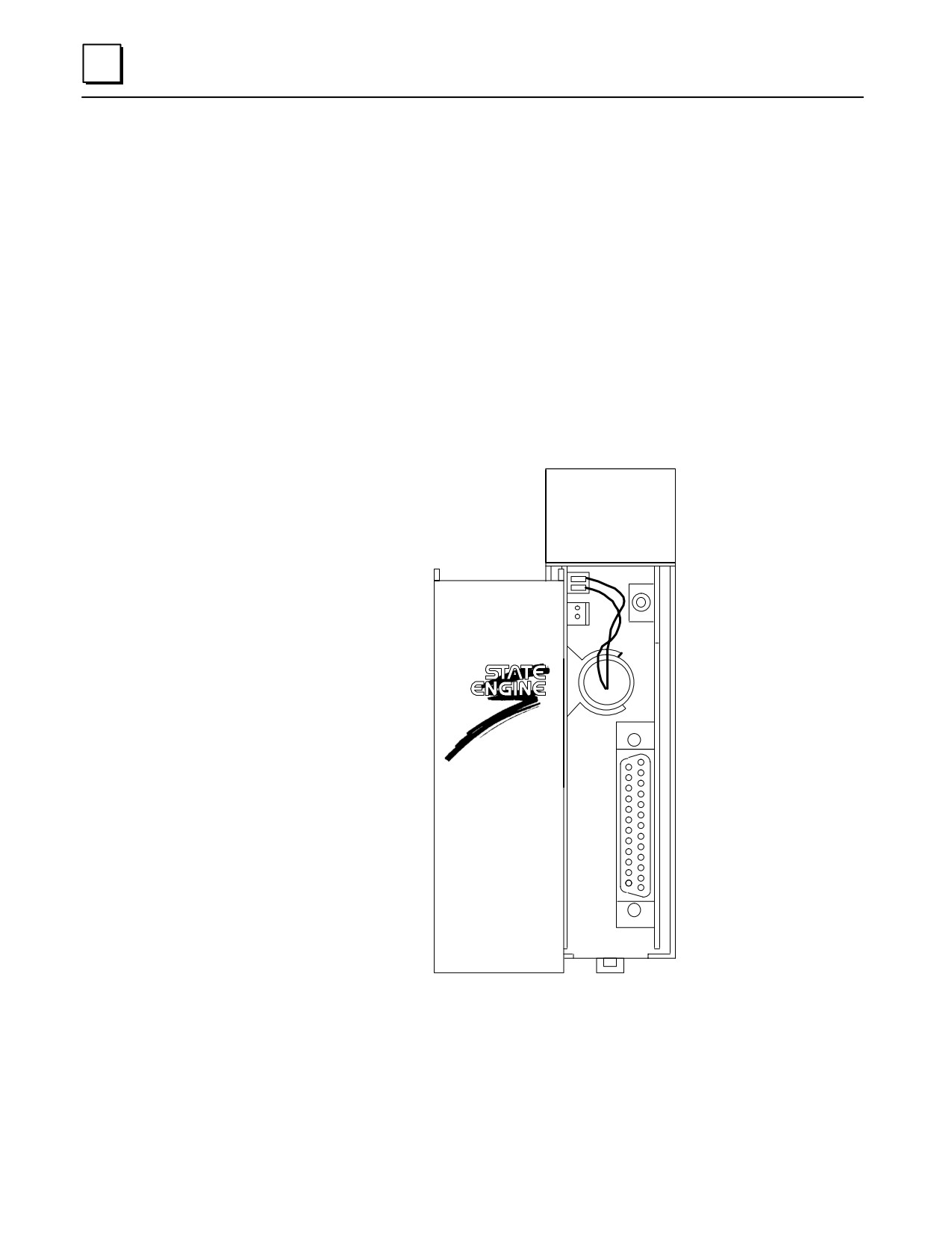
IC693SLP300 State Logic Processor Module
Description
The State Logic Processor Module (SLP) installs in a Series 90-30 PLC ladder logic con-
trol system to provide real time multi-tasking control for machine and process applica-
tions. It can be programmed to perform computations, data acquisition, data commu-
nications and operator interface functions. Also, the SLP module can provide machine
or process simulation capabilities to Series 90-30 PLC ladder logic control system to help
reduce debug and startup times. This dual processor architecture allows a user to create
both ladder logic and state logic application programs in any combination for efficient
parallel processing solutions.
The SLP is programmed using the English Control Language Programming System
(ECLiPS) software package. It communicates with the PLC CPU over the backplane and
can access user and system data. Many SLPs can be supported in a single Series 90-30
PLC system and each SLP can support up to 512 inputs and 512 outputs.
a45130
OK
ÎÎ
STATE LOGIC
PROCESSOR
Î
Î
Figure 9-3. IC693SLP300 State Logic Processor Module for Series 90-30
9-4
Series 90-30 PLC Installation and Hardware Manual - October 1999
GFK-0356P
9
SLP Features
Natural English Language Programming using ECLiPS
Structured State Logic program architecture
Advanced Diagnostics
Simulation capabilities
PID Loop control
Handles complex math easily (floating point, square root, trig. functions)
Allows any combination of Natural English State Logic and Ladder Logic programs
in same system
Configurable to operate with a Series 90-30 PLC system that uses a model 331, 340,
or 341 CPU
Up to 512 inputs and 512 outputs
CCM2 Protocol
8 Mhz, 80C188 microprocessor
46 Kbytes battery-backed CMOS logic memory on board
One RS-422/RS-485 port and one RS-232 serial port
Soft configuration (No DIP switches or jumpers)
Restart/ResetPushbutton
OK Status LED
Occupies a single slot in a Series 90-30 rack
Memor y
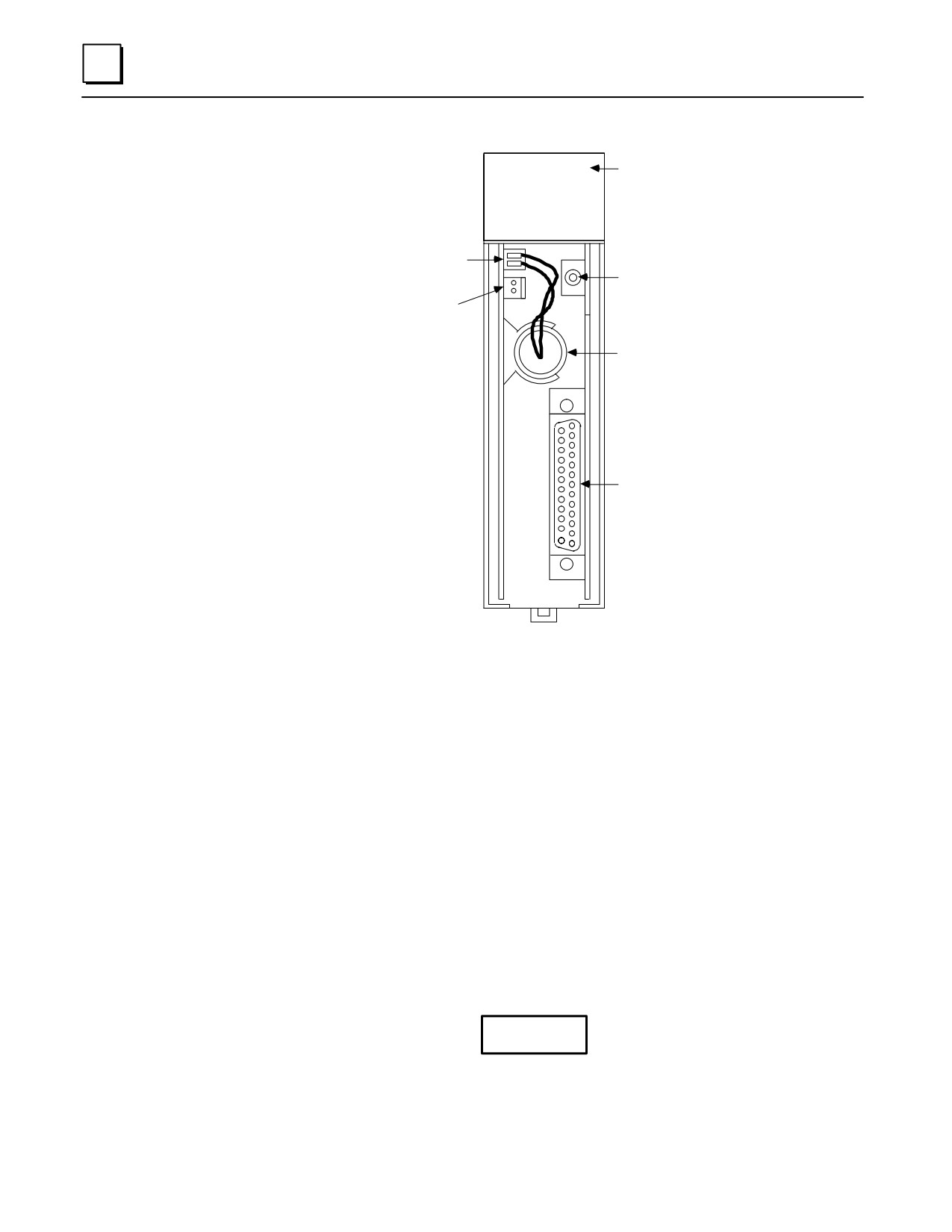
The SLP module has 46 Kbytes of user program memory space. Additional memory ex-
ists for Input, Output, Register, and other variable data. The battery which supports this
memory is located on the SLP module, as shown in the following figure.
Installation
Installation should not be attempted without referring to the State Logic Processor
User’s Guide (see reference 1).
The Series 90-30 SLP can only be installed in a Series 90-30 PLC system that uses a
model 331, model 340, or model 341 CPU.
Make sure rack power is off.
Connect the battery to either of the battery connectors on the module
(See figure G-3).
Install the SLP Module in the rack.
Turn on power.
The module should power up and blink the top LED, indicating that power up diagnos-
tics are in progress. When the diagnostics have completed successfully the top LED stays
on. The other LEDs on this module are not used and will always stay off.
GFK-0356P
Chapter 9 State Logic Products
9-5
9
a45131
OK
BD OK
CURRENTLY
INSTALLED
BATTERY
ÎÎ
CONNECTOR
RESTART
OPEN
REPLACEMENT
BATTERY
CONNECTOR
ÎÎÎÎ
BATTERY
ÎÎÎÎ
ÎÎÎÎ
PORTS
1 AND 2
SLP 300
Figure 9-4. State Logic Processor Module User Details
Status Light
Three Status LEDs exist on the SLP module. The top LED (see figure above) indicates
the condition of the module. It will blink ON and OFF while the module is booting up,
then will stay ON during normal operation. The bottom two LEDs are not used and will
always be off.
Pushbutton
See Caution note below before operating the pushbutton. One pushbutton is provided.
Pushing and holding the pushbutton for less than 5 seconds will simply restart the user
application program if it was configured to “auto-run” at power up. Pushing and hold-
ing for more than 5 seconds will reinitialize the module and require that the user ap-
plication program be reloaded.
Caution
Pushing and holding the pushbutton for more than 5 seconds will
reinitialize the module and require that the user application program
be reloaded.
9-6
Series 90-30 PLC Installation and Hardware Manual - October 1999
GFK-0356P
9
Battery
A lithium battery (IC697ACC301) is installed as shown in the previous figure. This bat-
tery maintains user memory when power is removed. Be sure to install a new battery
before removing the old battery (two connectors are provided). Indication of a low bat-
tery is provided through the ECLiPS programming system software and Logicmaster
90-30 software.
Cable Information
Cable IC693CBL305 can be used in applications that require use of both SLP serial ports.
This is a Wye-type cable that breaks out the Port 1 and Port 2 connections on the
module’s single connector to two individual connectors. A data sheet for this cable can
be found in the “Cables” chapter of this manual. (Additional SLP cable information is
found in publication GFK-0726 - see “Documentation” section.) This cable is not
required for applications that use only one SLP port.
Hardware Specifications
Battery:
Shelf Life
5 years at 20°C (68°F)
Memory Retention
6 months nominal without applied power
Internal Power Consumption
400 mA from 5V bus on backplane
Serial Ports:
TwoRS-232/422/485compatible
State Logic Processor (SLP) Documentation
Please refer to the following publications for more State Logic Processor information.
Title
GFK Number
Series 90-30 PLC State Logic Processor User’s Guide
GFK-0726
Series 90-30 PLC ECLiPS User’s Manual
GFK-0732
Series 90-30 PLC OnTOP User’s Guide
GFK-0747
OnTOP for Series 90-30 Online Troubleshooting and Operator Program
GFK-0750
User’s Manual
Series 90-30 State Logic Control System User’s Manual
GFK-1056
GFK-0356P
Chapter 9 State Logic Products
9-7
9
State Logic CPUs
Five models of State Logic CPUs are available that support State Logic programming.
Three of these CPUs are of the embedded baseplate type, and two are modular CPUs.
Data sheets for these modules are located at the back of this chapter. The available State
Logic CPUs for the Series 90-30 PLC are:
IC693CSE311 and IC693CSE313, both are 5-slot embedded CPU (CPU is built-in)
baseplates.
IC693CSE323, 10-slot embedded CPU baseplate.
IC693CSE331 and IC693CSE340, single-slot CPU modules (can be installed in
standard IC693CHS397 5-slot CPU baseplate, or standard IC693CHS391 10-slot CPU
baseplate).
Features of State Logic CPUs
Support State Logic programming
Support Floating Point calculations
Support Clock/Calendar functions (CSE331 and 340 are battery backed)
Support discrete and analog overrides
Programmed by State Logic software products
Provide from 10K to 98K Bytes of program memory depending on model
Program memory is battery backed
Control two Status LEDs on the power supply
Software configuration (no DIP switches or jumpers to set)
Serial port on power supply used as a programming port, a simple ASCII interface,
or a CCM port
Password controlled access
Support Series 90-30 I/O products
Alarm Processor Function for module diagnostics
Simulation mode
EPROM and EEPROM program memory
Store histogram of State Changes
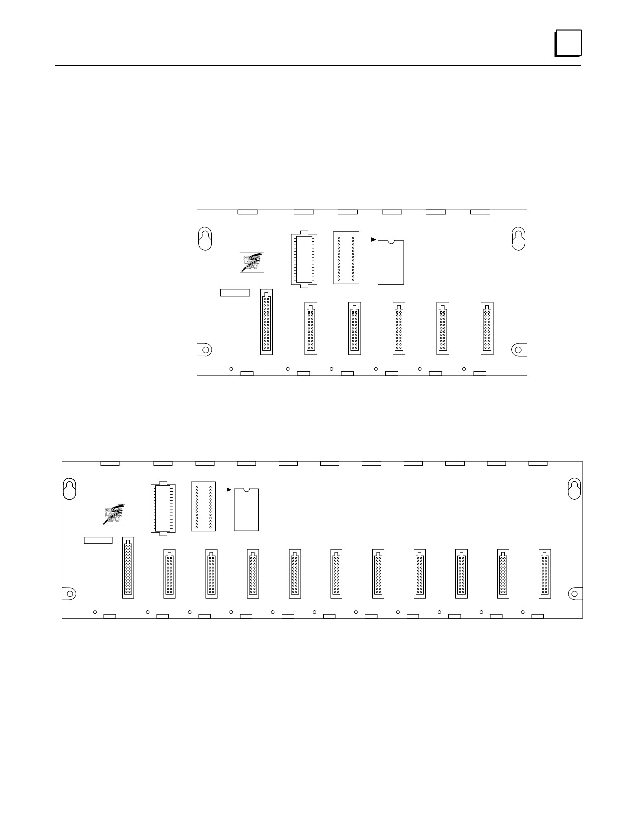
Model CSE311, CSE313 and CSE323 Embedded CPU Baseplates
The Programmable Logic Controller with a built-in State Logic CPU is available in three
models. The CSE311 and CSE313 with built-in CPU has 5 slots available for modules and
the CSE323 with built-in CPU has 10 slots available for modules. Each baseplate also has
a power supply slot.
The CSE 311, 313 and 323 CPUs can be programmed in the State Logic programming
language using the State Logic software products. The State logic software products are
also used to configure the Programmable Controller and communicate on-line with the
State Logic CPU for debugging and troubleshooting operations.
9-8
Series 90-30 PLC Installation and Hardware Manual - October 1999
GFK-0356P
9
The CSE311, CSE313, and CSE323 communicate with I/O modules, smart option
modules, and Third Party modules across the PLC backplane. Most of the available
Series 90-30 discrete, analog, and special purpose modules are supported (with Release
3.0 of State Logic). Foreign or 3rd party modules are also supported.
A socket labeled PROGRAM PROM is provided to install an EEPROM or EPROM. This
option allows the control program to be stored in a PROM instead of RAM memory. It also
is convenient in that it allows the PROM to be copied for installation in multiple CPUs.
a47063
PROGRAMMABLE
1
ÎÎ
CONTROLLER
ÎÎ
ÎÎ
CAUTION
SYSTEM
ÎÎ
PROGRAM
PROM
PROM
USER PROGRAM
AND REGISTER
VALUES MAY BE
LOST IF POWER
SUPPLY IS
REMOVED FOR
LONGER THAN
i HOUR
1
2
3
4
5
POWER
SUPPLY
Figure 9-5. Model CSE311 or CSE313 5-Slot Embedded CPU Baseplate
a47064
1
PROGRAMMABLE
CONTROLLER
CAUTION
SYSTEM
PROGRAM
PROM
PROM
USER PROGRAM
AND REGISTER
VALUES MAY BE
LOST IF POWER
SUPPLY IS
REMOVED FOR
LONGER THAN
1 HOUR.
POWER
1
2
3
4
5
6
7
8
9
10
SUPPLY
Figure 9-6. Model CSE323 10-Slot Embedded CPU Baseplate
GFK-0356P
Chapter 9 State Logic Products
9-9
9
Model CSE331 and CSE340 Modular CPUs
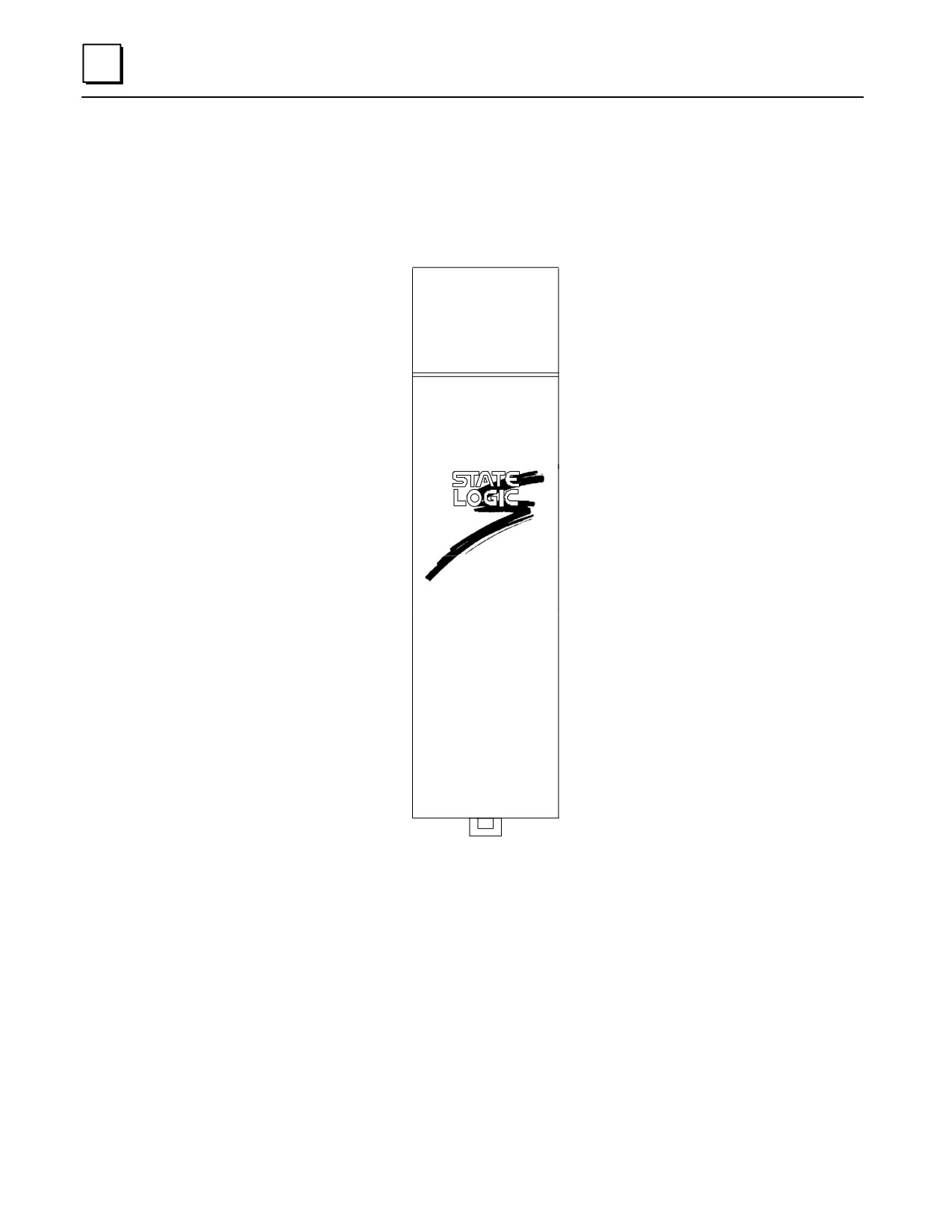
The CSE 331 CPU (IC693CSE331) and CSE 340 (IC693CSE340) CPUs are single slot
modules which must be installed in slot one (labeled CPU/1) of a CPU baseplate
(IC693CHS391 or IC693CHS397). An illustration of the State Logic CPU modules is
shown below.
a45454
STATE LOGIC
CPU
Figure 9-7. CPU Models CSE 331 or CSE 340
The CSE 331 and CSE 340 CPU modules provide the same functionality as the models
CSE 311, 313 and 323, and offer several more advanced features such as more I/O points
and more User Program memory. See the table at the end of this chapter to compare
CPU specifications.
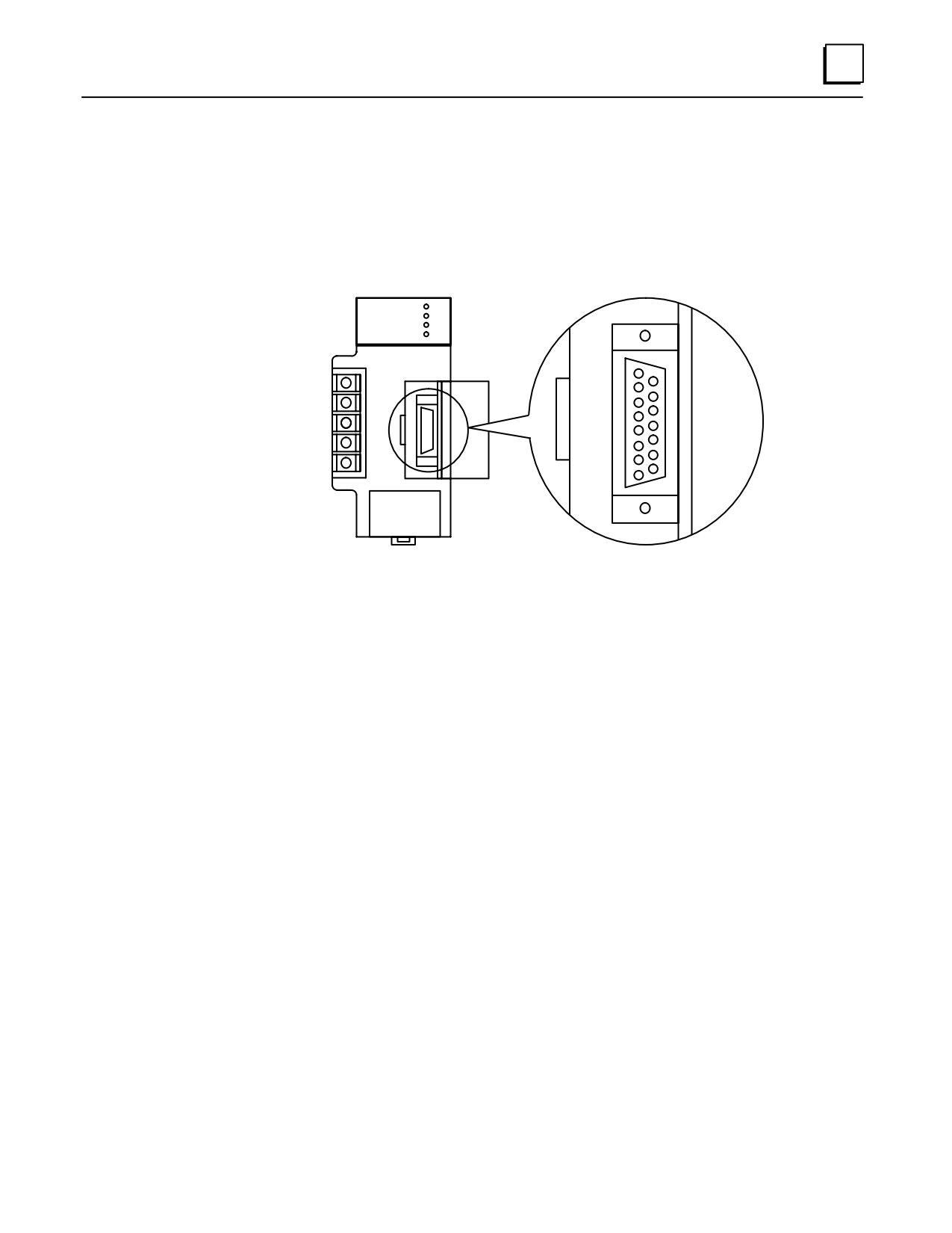
CPU Serial Port Connector on Power Supply
The 15-pin D-connector provides the connection to an RS-485 compatible serial port.
The connection is made from the serial port on the power supply to the serial port on the
programming computer or other serial device through the RS-422/RS-485 to RS-232
Converter (IC690ACC900) or RS-422 to RS-232 Miniconverter (IC690ACC901).
9-10
Series 90-30 PLC Installation and Hardware Manual - October 1999
GFK-0356P
9
The serial port has three possible uses:
as a programming port for the State Logic software to download programs and to
send instructions to the PLC;
as an ASCII port providing a connection from the CPU to any ASCII device;
as a CCM port providing an interface connection for MMI and other host computer
systems.
a43832
ÎÎÎÎ
ÎÎ
RS-485
COMPATIBLE
SERIAL PORT
Figure 9-8. Serial Port Connector
Notes
The serial port connector is functional only in a power supply that is
installed in a baseplate that also contains the CPU; this includes the
Model CSE 311 and CSE 313 5-slot baseplates with built-in CPU, CSE
323 10-slot baseplate with built-in CPU, and the Model CSE 331 and
CSE 340 single slot CPUs.
The serial port is not functional when a power supply is installed in a Series
90-30 expansion or remote baseplate.
Additionally, any device connected to the serial port that uses +5 VDC
power from the Series 90-30 power supply must be included in the
calculation for maximum power consumption (see Sample Calculations
for Power Supply Loads in Chapter 3 of this manual).
Configuring the State Logic CPUs
All of the State Logic CPUs and attached I/O system are configured with the State Logic
software. There are no DIP switches or jumpers used to configure the system. The CPU
verifies the actual module configuration at power-up and periodically throughout the
operation. The actual configuration must match the programmed configuration. Any
detected deviations are reported to the CPU alarm processor function for the configured
fault response. Refer to GFK-1056, the Series 90-30 State Logic CPU User’s Manual for
more information.
GFK-0356P
Chapter 9 State Logic Products
9-11
9
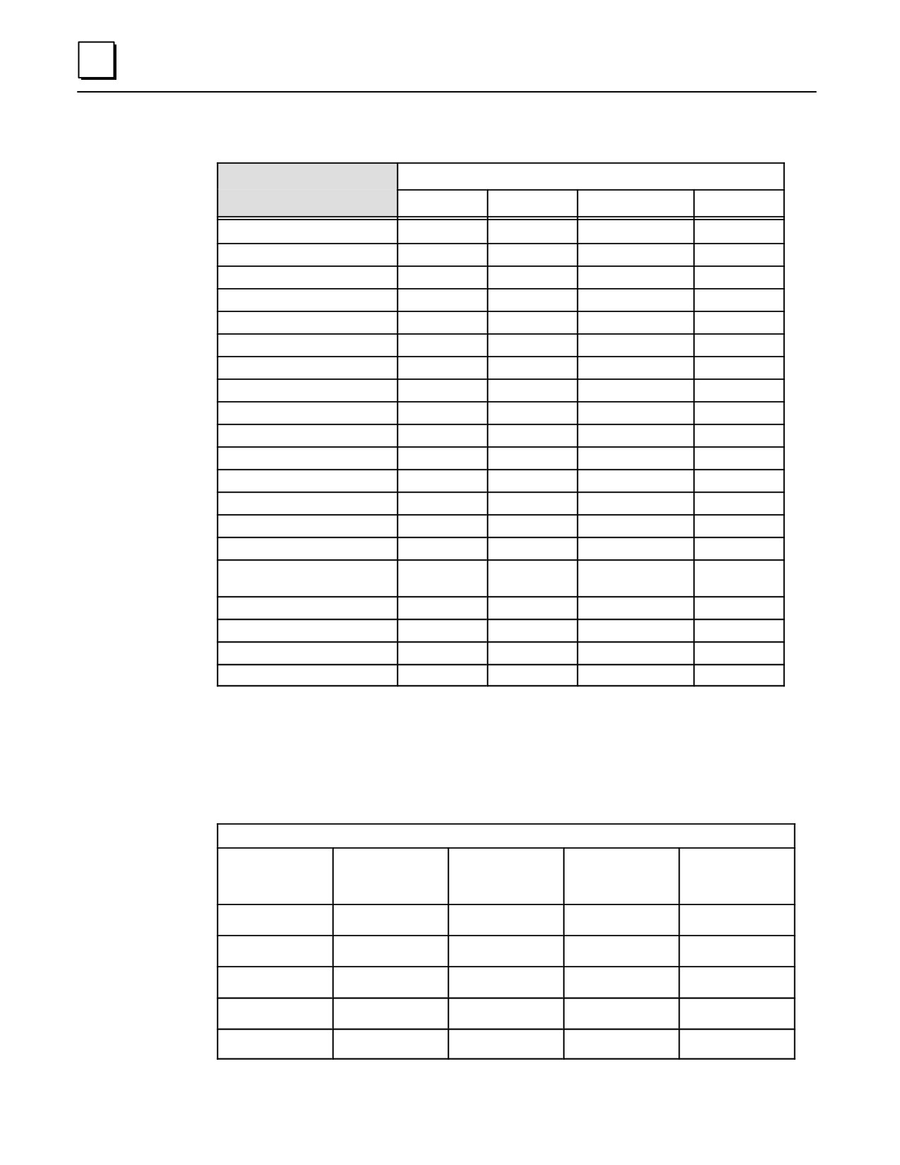
Table 9-1. System Specifications for Series 90-30 State Logic CPUs
State Logic CPU Model
CSE 340
CSE 331
CSE 313/323
CSE 311
Digital Inputs, %I
1024
1024
512
512
Digital Outputs, %Q
1024
1024
512
512
GlobalI/O, %G
1280
1280
1280
1280
Internal Flags
1000
1000
500
500
Analog Inputs, %AI
256
256
128
128
Analog Outputs, %AQ
128
128
64
64
PID Loops
20
20
20
20
Integer Variables
1000
1000
250
250
Floating Point Variables
250
250
61
61
String Variables
20
20
8
8
Character Variables
64
64
64
64
Tables
20
20
10
10
ProgramMemory
98K Bytes
48K Bytes
20K Bytes
10K Bytes
Processor Speed
20 MHz
10 MHz
10 MHz
10 MHz
Number of Baseplates
5
5
1
1
Baseplate Size
5 or 10 slots
5 or 10 slots
5 slots (CSE313)
5 slots
10 slots (CSE323)
Supports SCM
Yes
Yes
No
No
Serial Ports
1
1
1
1
Clock/Calendar
Hardware
Hardware
Software
Software
Table Memory Space
4K Bytes
4K Bytes
1K Bytes
1K Bytes
For more detailed information on State Logic CPU specifications, see GFK-1056, the
Series 90-30 State Logic Control System User’s Manual.
State Logic CPU Firmware and PROM Configurations
State Logic CPU Firmware and PROM Table
Firmware
EPROM
EEPROM
Flash
CPU
(standard)
(for user
(for user
(for user
memor y)
memor y)
memor y)
CSE311
Optional
N/A
EPROM
N/A
CSE313
EPROM
Optional
N/A
N/A
CSE323
EPROM
Optional
N/A
N/A
CSE331
EPROM
Optional
N/A
N/A
CSE340
EPROM
N/A
Optional
N/A
9-12
Series 90-30 PLC Installation and Hardware Manual - October 1999
GFK-0356P
9
State Logic CPU Data Sheets
This section provides data sheets describing each of the Series 90-30 State Logic CPU
modules. Each CPU is described in a one-page data sheet, which provides a quick
reference to all of the available CPU models.
IC693CSE311
State Logic, 5-slot baseplate with embedded CPU
IC693CSE313
State Logic, 5-slot baseplate with embedded CPU
IC693CSE323
State Logic, 10-slot baseplate with embedded CPU
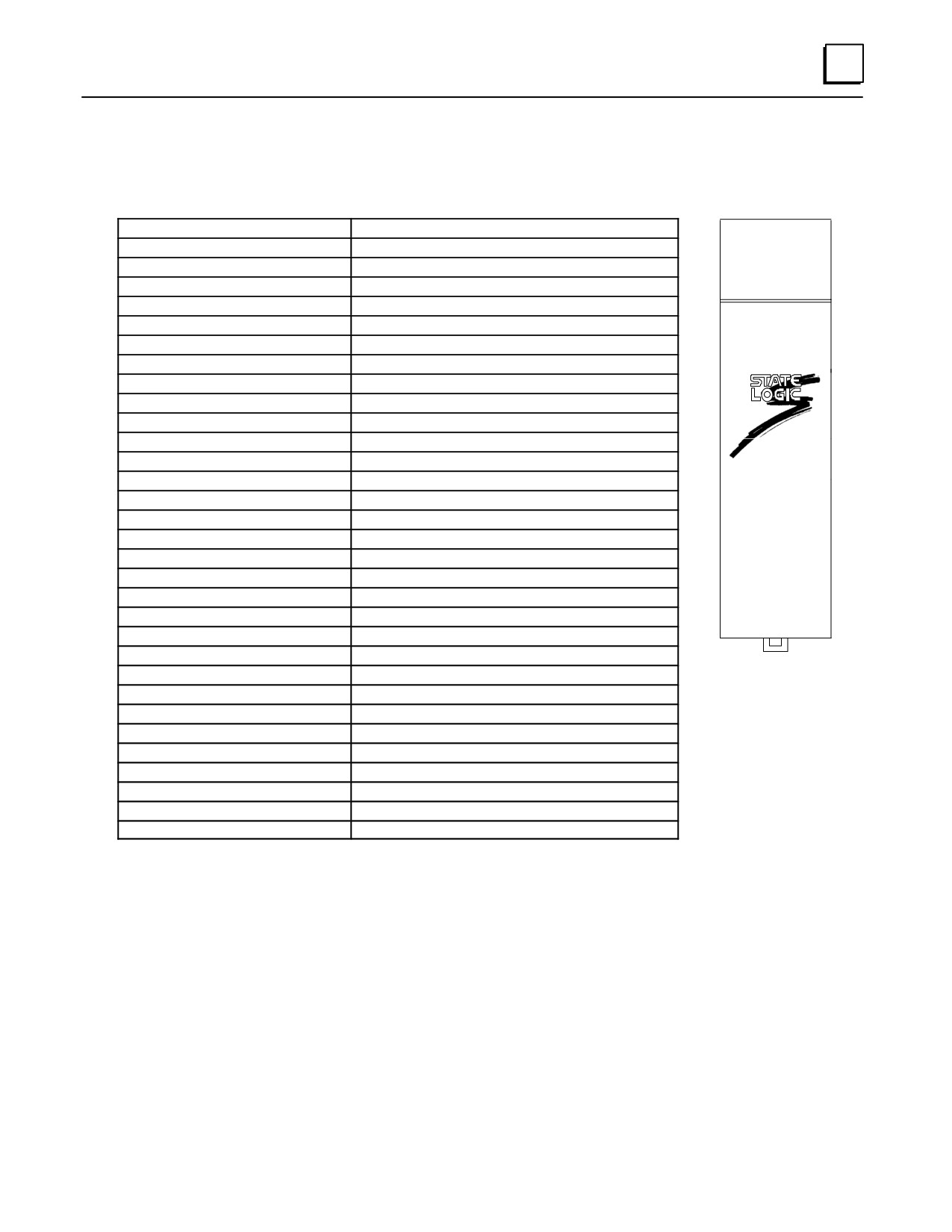
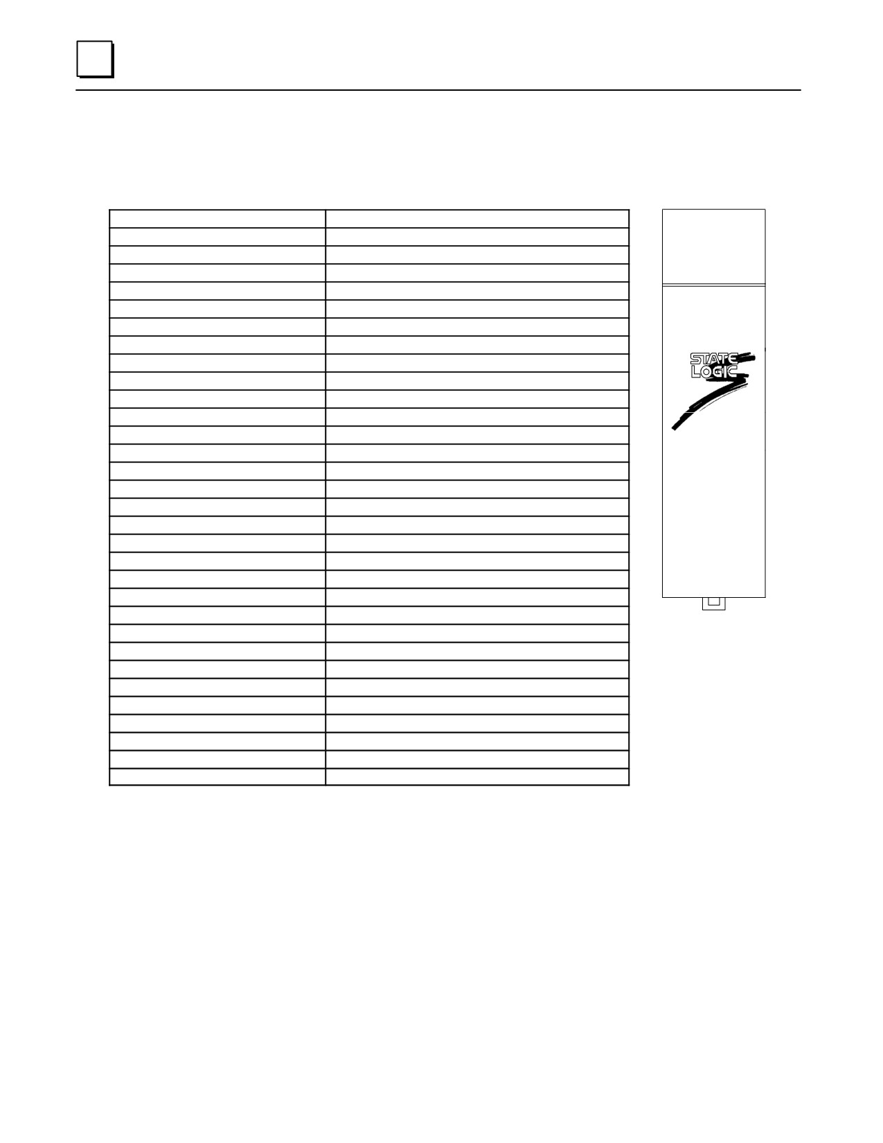
IC693CSE331
State Logic, CPU module, 10 MHz
IC693CSE340
State Logic, CPU module, 20 MHz
GFK-0356P
Chapter 9 State Logic Products
9-13
9
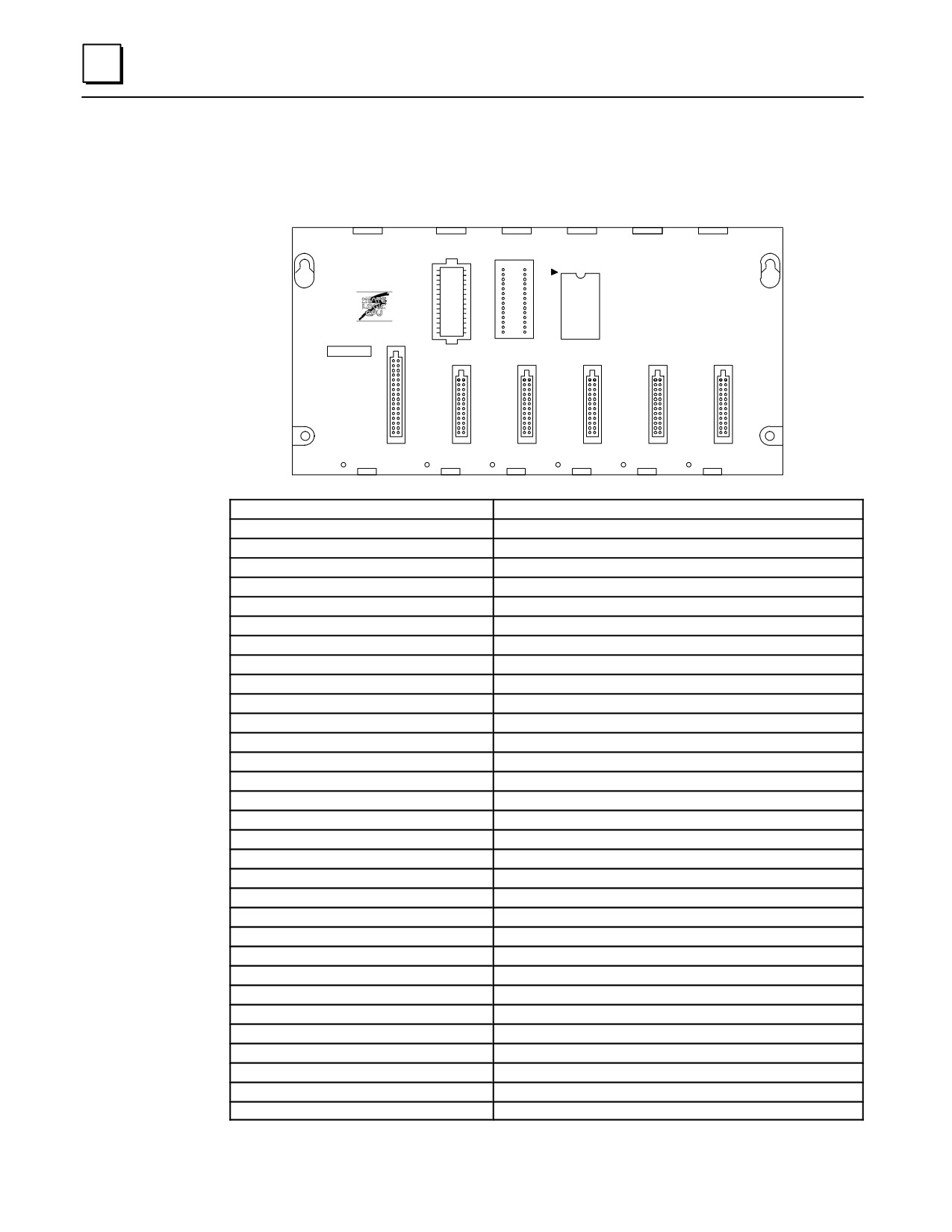
Catalog Number IC693CSE311
a47063
PROGRAMMABLE
1
CONTROLLER
ÎÎ
ÎÎ
ÎÎ
CAUTION
SYSTEM
PROGRAM
PROM
PROM
USER PROGRAM
AND REGISTER
VALUES MAY BE
LOST IF POWER
SUPPLY IS
REMOVED FOR
LONGER THAN
i HOUR
1
2
3
4
5
POWER
SUPPLY
CPU Type
State Logic 5-slot baseplate with embedded CPU
Total Baseplates per System
1
Load Required from Power Supply
410 milliamps from +5 VDC supply
Processor Type and Speed
80188, 10 MegaHertz
Typical Scan Rate
18 milliseconds per 1K of logic (boolean contacts)
Serial Ports
1
Type of memory Storage
RAM, EPROM, EEPROM
Clock
Software
ProgramMemory
10K Bytes
Digital I/O (%I, %Q)
1024
Tasks
256
Task Groups
16
States per task
254
I/O and VariableNames
3000
Analog Inputs and Outputs
128 (%AI), 64 (%AQ)
Internal Flags
500
%G
1280
%T, %S, %M, %R
n/a
Integer Variables
250
Floating Point Variables
61
String Variables
8
Characters / String
80
Character Variables
64
Characters / Write
512
Serial Protocols
SNP, CCM
Tables
10
TableMemory (Bytes)
1K
Timers
Unlimited
Timer Resolution
.01 seconds
Timer-Counters
100
Trace Size
100
PID Loops
20
9-14
Series 90-30 PLC Installation and Hardware Manual - October 1999
GFK-0356P
9
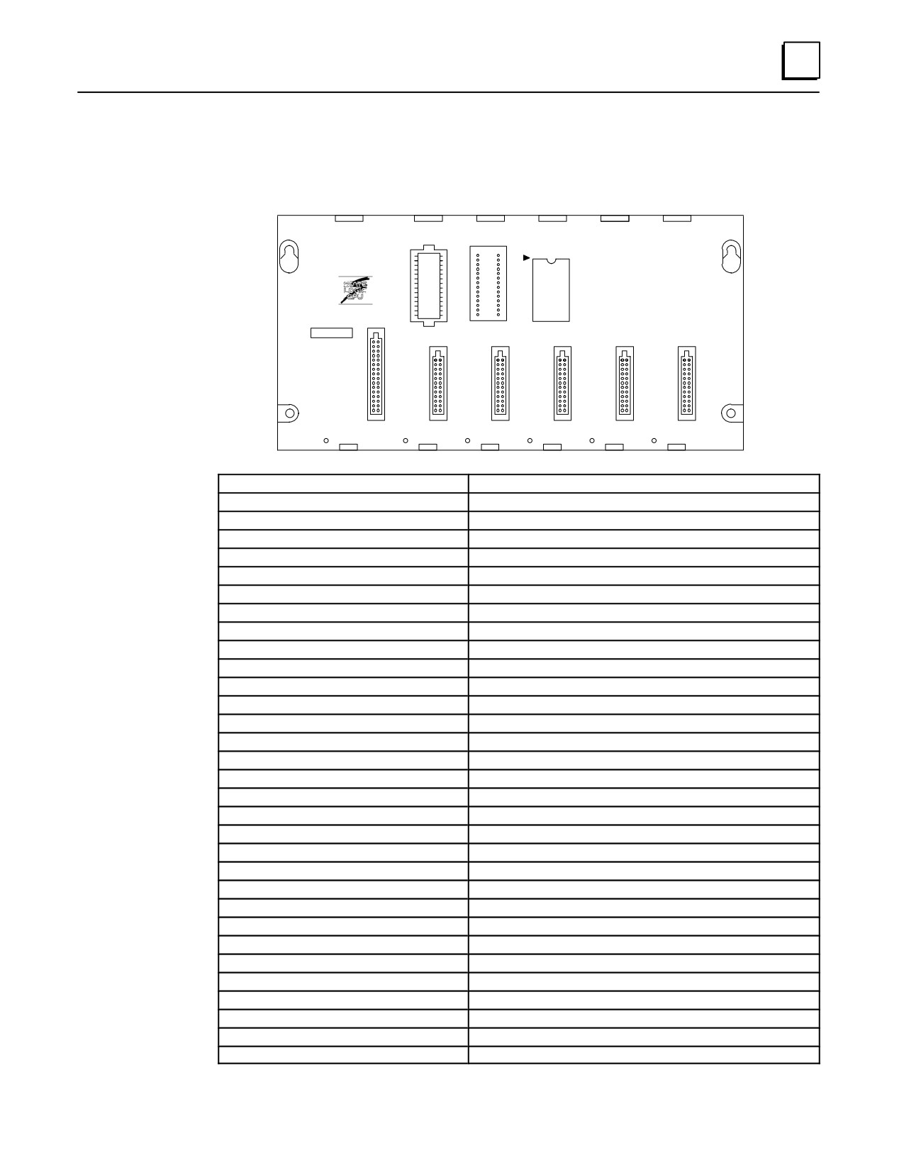
Catalog Number IC693CSE313
a47063
ÎÎ
PROGRAMMABLE
1
CONTROLLER
ÎÎ
ÎÎ
ÎÎ
CAUTION
SYSTEM
PROGRAM
PROM
PROM
USER PROGRAM
AND REGISTER
VALUES MAY BE
LOST IF POWER
SUPPLY IS
REMOVED FOR
LONGER THAN
i HOUR
1
2
3
4
5
POWER
SUPPLY
CPU Type
State Logic 5-slot baseplate with embedded CPU
Total Baseplates per System
1
Load Required from Power Supply
430 milliamps from +5 VDC supply
Processor Type and Speed
80188, 10 MegaHertz
Typical Scan Rate
0.6 milliseconds per 1K of logic (boolean contacts)
Serial Ports
1
Type of Memory Storage
RAM, EPROM, EEPROM
Clock
Software
ProgramMemory
20K Bytes
Digital I/O (%I, %Q)
1024
Tasks
256
Task Groups
16
States per task
254
I/O and VariableNames
3000
Analog Inputs and Outputs
128 (%AI), 64 (%AQ)
Internal Flags
500
%G
1280
%T, %S, %M, %R
n/a
Integer Variables
250
Floating Point Variables
61
String Variables
8
Characters / String
80
Character Variables
64
Characters / Write
512
Serial Protocols
SNP, CCM
Tables
10
TableMemory (Bytes)
1K
Timers
Unlimited
Timer Resolution
.01 seconds
Timer-Counters
100
Trace Size
100
PID Loops
20
GFK-0356P
Chapter 9 State Logic Products
9-15
9
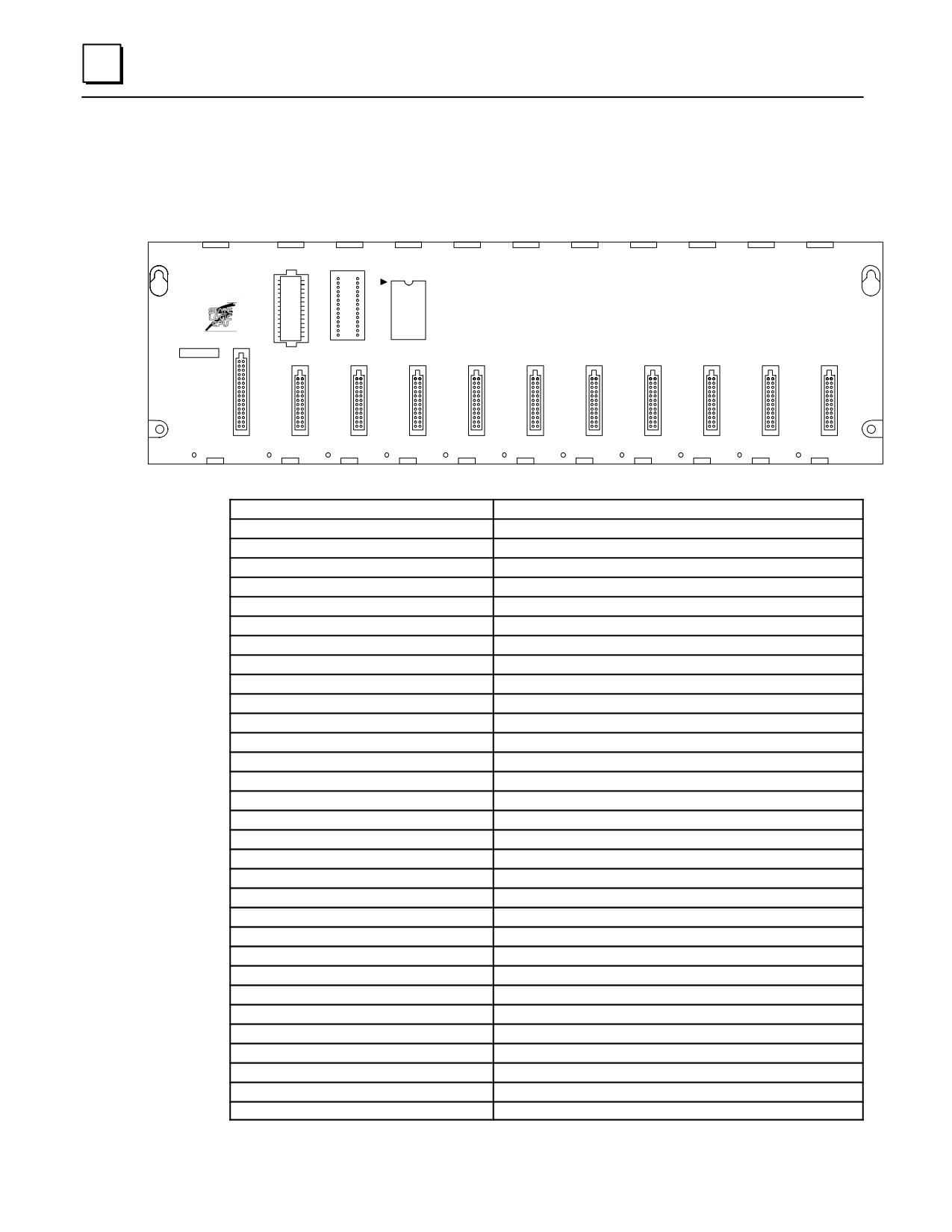
Catalog Number IC693CSE323
a47064
1
PROGRAMMABLE
CONTROLLER
CAUTION
SYSTEM
PROGRAM
PROM
PROM
USER PROGRAM
AND REGISTER
VALUES MAY BE
LOST IF POWER
SUPPLY IS
REMOVED FOR
LONGER THAN
1 HOUR.
POWER
1
2
3
4
5
6
7
8
9
10
SUPPLY
CPU Type
State Logic 10-slot baseplate with embedded CPU
Total Baseplates per System
1
Load Required from Power Supply
430 milliamps from +5 VDC supply
Processor Type and Speed
80188, 10 MegaHertz
Typical Scan Rate
0.6 milliseconds per 1K of logic (boolean contacts)
Serial Ports
1
Type of Memory Storage
RAM, EPROM, EEPROM
Clock
Software
ProgramMemory
20K Bytes
Digital I/O (%I, %Q)
1024
Tasks
256
Task Groups
16
States per task
254
I/O and VariableNames
3000
Analog Inputs and Outputs
128 (%AI), 64 (%AQ)
Internal Flags
500
%G
1280
%T, %S, %M, %R
n/a
Integer Variables
250
Floating Point Variables
61
String Variables
8
Characters / String
80
Character Variables
64
Characters / Write
512
Serial Protocols
SNP, CCM
Tables
10
TableMemory (Bytes)
1K
Timers
Unlimited
Timer Resolution
.01 seconds
Timer-Counters
100
Trace Size
100
PID Loops
20
9-16
Series 90-30 PLC Installation and Hardware Manual - October 1999
GFK-0356P
9
Catalog Number IC693CSE331
a45454
CPU Type
State Logic single slot CPU module
Total Baseplates per System
5 (1 CPU baseplate + 4 expansion and/or remote baseplates)
Load Required from Power Supply
350 milliamps from +5 VDC supply
Processor Type and Speed
80188, 10 MegaHertz
Typical Scan Rate
0.4 milliseconds per 1K of logic (boolean contacts)
Serial Ports
1
STATE LOGIC
Type of Memory Storage
RAM, EPROM, EEPROM
CPU
Clock
Hardware
ProgramMemory
48K Bytes
Digital I/O (%I, %Q)
2048
Tasks
256
Task Groups
16
States per task
254
I/O and VariableNames
3000
Analog Inputs and Outputs
256 (%AI), 128 (%AQ)
Internal Flags
1000
%G
1280
%T, %S, %M, %R
n/a
Integer Variables
1000
Floating Point Variables
497
String Variables
20
Characters / String
80
Character Variables
64
Characters / Write
512
Serial Protocols
SNP, CCM, RTU
Tables
20
TableMemory (Bytes)
4K
Timers
Unlimited
Timer Resolution
.01 seconds
Timer-Counters
100
Trace Size
100
PID Loops
20
GFK-0356P
Chapter 9 State Logic Products
9-17
9
Catalog Number IC693CSE340
a45454
CPU Type
State Logic single slot CPU module
Total Baseplates per System
5 (1 CPU baseplate + 4 expansion and/or remote baseplates)
Load Required from Power Supply
490 milliamps from +5 VDC supply
Processor Type and Speed
80C188XL, 20 MegaHertz
Typical Scan Rate
0.3 milliseconds per 1K of logic (boolean contacts)
Serial Ports
1
STATE LOGIC
CPU
Type of Memory Storage
RAM, Flash, EEPROM
Clock
Hardware
ProgramMemory
98K Bytes
Digital I/O (%I, %Q)
2048
Tasks
256
Task Groups
16
States per task
254
I/O and VariableNames
3000
Analog Inputs and Outputs
256 (%AI), 128 (%AQ)
Internal Flags
1000
%G
1280
%T, %S, %M, %R
n/a
Integer Variables
1000
Floating Point Variables
497
String Variables
20
Characters / String
80
Character Variables
64
Characters / Write
512
Serial Protocols
SNP, CCM, RTU
Tables
20
TableMemory (Bytes)
4K
Timers
Unlimited
Timer Resolution
.01 seconds
Timer-Counters
100
Trace Size
100
PID Loops
20
9-18
Series 90-30 PLC Installation and Hardware Manual - October 1999
GFK-0356P

Chapter
Cables
10
The following table serves as a cable catalog number/application cross-reference:
Table 10-1. Series 90-30 Cable Cross-Reference
Series 90-30 Cable Cross-Reference
Catalog No.
Description
Applications
A03B-0807-K802
33’ (10 meter) I/O Link module
I/O Link modules:
(Equivalent to
to module cable. See publication
IC693BEM321 (Master)
catalog number
GFK-0823 for details on I/O Link
IC693BEM320(Slave/Interface)
44C741558-004)
cables.
A03B-0807-K803
1.5’ (0.45) meter I/O Link optical
I/O Link modules:
(Equivalent to
adapter to module cable. See
IC693BEM321 (Master)
catalog number
publication GFK-0823 for details
IC693BEM320(Slave/Interface)
44C741558-002)
on I/O Link cables.
A66L-6001-009#
I/O Link fiber optic cable,
I/O Link modules:
Lxxxxx
available in ten lengths. Catalog
IC693BEM321 (Master)
Note: xxxxx
number depends on length. For
IC693BEM320(Slave/Interface)
portion of the
example, the 10 meter cable’s
number depends
catalog number is
on the cable
A66L-6001-009#L10R03.
length. Lengths
See publication GFK-0823 for
are 10, 15, 20, 30,
details on these length choices.
40, 50, 60, 80, 90,
and 100 meters.
IC647CBL704
Programmer serial cable to
For GE Fanuc Work Station
connect Work Station Interface
Interface (WSI) boards:
board to the serial connector on
IC647WMI310
the PLC Power Supply.
IC647WMI320
IC690ACC901
Contains RS-422 to RS-232
For connecting a computer ’s
Miniconverter
miniconverter, a 6’ (2 meter)
RS-232 serial port to a PLC
and cable kit
serial cable, and a 9-pin to 25-pin
RS-422/485 serial port. See
adapter.
Appendix F for details on this
product.
IC690CBL701
Connects a PCM, CMM, or ADC
Use with the following
module to a GE Fanuc
modules:
(Note: Used on
Workmaster I or IBM XT or
IC693PCM300/301/311,
older computers)
compatible personal computer.
IC693CMM311
IC693ADC311
IC690CBL702
Connects a PCM, CMM, or ADC
Use with the following
module to an IBM AT or
modules:
compatible personal computer.
IC693PCM300/301/311,
IC693CMM311
IC693ADC311
10-1
GFK-0356P

10
IC690CBL705
Connects a PCM, CMM, or ADC
Use with the following
module to a GE Fanuc
modules:
Workmaster II or IBM PS/2 or
IC693PCM300/301/311,
compatible personal computer
IC693CMM311
IC693ADC311
IC690CBL714A
Dual-port multi-drop cable.
Series 90 PLCs.
Allows the interconnecting of
individual PLCs using SNP serial
ports. Connections are in a
daisy-chain configuration.
IC693CBK002
Cable kit. Contains both the
Used with Terminal Block Quick
IC693CBL329 and IC693CBL330
Connect (TBQC) assemblies.
3’ (1 m) cables. Used for
See appendix J for a module list
32-point I/O modules having
and cable selection information.
dual 24-pin connectors.
See also, the data sheet for the
IC693CBL329/330/331/332/333/334
cables for additional
information.
IC693CBK003
Cable kit. Contains both the
Used with Terminal Block Quick
IC693CBL331 and IC693CBL332
Connect (TBQC) assemblies.
6’ (2 m) cables. Used for
See appendix J for a module list
32-point I/O modules having
and cable selection information.
dual 24-pin connectors.
See also, the data sheet for the
IC693CBL329/330/331/332/333/334
cables for additional
information.
IC693CBK004
Cable kit. Contains both the
Used with Terminal Block Quick
IC693CBL333 and IC693CBL334
Connect (TBQC) assemblies.
19” (0.5 m) cables. Used for
See appendix J for a module list
32-point I/O modules having
and cable selection information.
dual 24-pin connectors.
See also, the data sheet for the
IC693CBL329/330/331/332/333/334
cables for additional
information.
IC693CBL300
3’ (1 meter) I/O expansion cable
To interconnect CPU, expansion,
interconnects baseplate
and remote baseplates.
expansion ports. This is a Wye
type cable for daisy-chaining
baseplates.
IC693CBL301
6’ (2 meter) I/O expansion cable
To interconnect CPU, expansion,
interconnects baseplate
and remote baseplates.
expansion ports. This is a Wye
type cable for daisy-chaining
baseplates.
IC693CBL302
50’ (15 meter) I/O expansion
To interconnect CPU, expansion,
cable interconnects baseplate
and remote baseplates.
Note:
expansion ports. This is a special
This cable is
type with built-in termination
identical to cable
resistors. It is not a Wye type
IC693CBL314
cable - it is for use as the last
cable on the link.
10-2
Series 90-30 PLC Installation and Hardware Manual - October 1999
GFK-0356P

10
IC693CBL303
Programmer serial cable to
For Hand-Held Programmer:
connect Hand-Held
IC693PRG300
Programmer (HHP) to serial
connector on PLC Power Supply.
IC693CBL304
Wye cable for splitting out two
For use with:
serial port connections from one
IC693PCM300 module
module connector.
IC693CBL305
Wye cable for splitting out two
For use with the following
serial port connections from one
modules:
module connector. (Use cable
IC693PCM301
IC693CBL304 with the
IC693PCM311
IC693PCM300 module.)
IC693CMM311
IC693ADC311
AD693CMM301
IC693SLP300
IC693CBL306
3’ (1 meter) extension cable
For High Density (32-point) I/O
connects between the 50-pin
modules having a single 50-pin
connector on the module
connector:
faceplate and the connector on
IC693MDL652
the terminal block.
IC693MDL653
IC693MDL750
IC693MDL751
IC693CBL307
6’ (2 meter) extension cable
For High Density (32-point) I/O
connects between the 50-pin
modules having a single 50-pin
connector on the module
connector:
faceplate and the connector on
IC693MDL652
the terminal block.
IC693MDL653
IC693MDL750
IC693MDL751
IC693CBL308
3’ (1 meter) I/O cable connects to
For High Density (32-point) I/O
the 50-pin connector on the
modules having a single 50-pin
module faceplate. The other
connector:
end has stripped, tinned, and
IC693MDL652
labeled leads.
IC693MDL653
IC693MDL750
IC693MDL751
IC693CBL309
6’ (2 meter) I/O cable connects to
For High Density (32-point) I/O
the 50-pin connector on the
modules having a single 50-pin
module faceplate. The other
connector:
end has stripped, tinned, and
IC693MDL652
labeled leads.
IC693MDL653
IC693MDL750
IC693MDL751
IC693CBL310
10’ (3 meter) I/O cable connects
For High Density (32-point) I/O
to one of the 24-pin connectors
modules having dual 24-pin
(Obsolete. Use
on the module. The other end
connectors:
IC693CBL327
has stripped, tinned, and labeled
IC693MDL654
and
leads. This cable was obsoleted
IC693MDL655
IC693CBL328)
and replaced by IC693CBL315,
IC693MDL752
until that cable also was
IC693MDL753
obsoleted. Two cables are
required per module.
GFK-0356P
Chapter 10 Cables
10-3

10
IC693CBL311
10’ (3 meter) APM I/O cable
APM modules:
connects between one of the
IC693APU301
24-pin connectors on the
IC693APU302
module and the connector on
the terminal block.
Two cables are required per
module.
IC693CBL312
0.5’ (152 mm) I/O expansion
To interconnect CPU, expansion,
cable interconnects baseplate
and remote baseplates.
expansion ports. This is a Wye
type cable for daisy-chaining
baseplates.
IC693CBL313
26’ (8 meter) I/O expansion cable
To interconnect CPU, expansion,
interconnects baseplate
and remote baseplates.
expansion ports. This is a Wye
type cable for daisy-chaining
baseplates.
IC693CBL314
50’ (15 meter) I/O expansion
To interconnect CPU, expansion,
cable interconnects baseplate
and remote baseplates.
Note:
expansion ports. This is a special
This cable is
type with built-in termination
identical to cable
resistors. It is not a Wye type
IC693CBL302
cable - it is for use as the last
cable on the link.
IC693CBL315
10’ (3 meter) I/O cable connects
For High Density (32-point) I/O
to one of the 24-pin connectors
modules having dual 24-pin
(Obsolete. Use
on the module. The other end
connectors:
IC693CBL327
has stripped, tinned, and labeled
IC693MDL654
and
leads.
IC693MDL655
IC693CBL328)
Two cables are required per
IC693MDL752
module.
IC693MDL753
IC693CBL316
3’ (1 meter) serial cable with
For connecting to modules with
9-pin D-shell connector that
an RJ-11 communications port:
connects to a Personal
IC693CMM321
Computer ’s serial port. The
IC693CPU351, 352, 363
other end has an RJ-11
IC693DSM302, 314
connector.
IC693CBL317
Special 10’ (3 meter) APM I/O
APM modules:
cable connects between one of
IC693APU301
the 24-pin connectors on the
IC693APU302s
module and the connector on
the terminal block. This cable is
similar to IC693CBL311 except
that its drain shield wire is
brought outside of the
connector.
Two cables are required per
module.
IC693CBL318
Unused or inactive number
10-4
Series 90-30 PLC Installation and Hardware Manual - October 1999
GFK-0356P

10
IC693CBL319
3’ (1 meter) APM I/O cable
APM modules:
connects between one of the
IC693APU301
24-pin connectors on the
IC693APU302
module and the connector on
the terminal block.
Two cables are required per
module.
IC693CBL320
Special 3’ (1 meter) APM I/O
APM modules:
cable connects between one of
IC693APU301
the 24-pin connectors on the
IC693APU302
module and the connector on
the terminal block. This cable is
similar to IC693CBL319 except
that its drain shield wire is
brought outside of the
connector.
Two cables are required per
module.
IC693CBL321
3’ (1 meter) I/O cable connects
Used with the Terminal Block
between a 24-pin connector on
Quick Connect assemblies. See
(Obsolete. Use
the module and the connector
Appendix J for a module list and
IC693CBL329
on the terminal block.
cable selection information.
and
IC693CBL330)
IC693CBL322
6’ (2 meter) I/O cable connects
Used with the Terminal Block
between a 24-pin connector on
Quick Connect assemblies. See
(Obsolete. Use
the module and the connector
Appendix J for a module list and
IC693CBL331
on the terminal block.
cable selection information.
and
IC693CBL332)
IC693CBL323
1.5’ (0.5 meter) I/O cable
Used with the Terminal Block
connects between a 24-pin
Quick Connect assemblies. See
(Obsolete. Use
connector on the module and
Appendix J for a module list and
IC693CBL333
the connector on the terminal
cable selection information.
and
block.
IC693CBL334)
IC693CBL324
3’ (1 meter) cable connects
DSM modules:
between a DSM module and
IC693DSM302
either a servos axis terminal
IC693DSM314
block or an aux axis terminal
block. See the DSM user ’s
manuals (GFK-1464, GFK-1742)
for details.
IC693CBL325
10’ (3 meter) cable connects
DSM modules:
between a DSM module and
IC693DSM302
either a servo axis terminal
IC693DSM314
block or an aux axis terminal
block. See the DSM user ’s
manuals (GFK-1464, GFK-1742)
for details.
IC693CBL326
Unused or inactive number
GFK-0356P
Chapter 10 Cables
10-5

10
IC693CBL327
10’ (3 meter) right angle I/O
For High Density (32-point) I/O
cable connects to the left side
modules having dual 24-pin
24-pin connector on a 32-point
connectors:
module. The other end has
IC693MDL654
stripped, tinned, and labeled
IC693MDL655
leads. Replaces straight cable
IC693MDL752
IC693CBL315 on the left side of
IC693MDL753
the module.
IC693CBL328
10’ (3 meter) right angle I/O
For High Density (32-point) I/O
cable connects to the right side
modules having dual 24-pin
24-pin connector on a 32-point
connectors:
module. The other end has
IC693MDL654
stripped, tinned, and labeled
IC693MDL655
leads. Replaces straight cable
IC693MDL752
IC693CBL315 on the right side
IC693MDL753
of the module.
IC693CBL329
3’ (1 meter) right angle I/O cable
Used with the Terminal Block
connects between the left side
Quick Connect (TBQC)
24-pin connector on a 32-point
assemblies. See Appendix J for a
module and the connector on
module list and cable selection
the terminal block. Replaces
information.
cable IC693CBL321.
IC693CBL330
3’ (1 meter) right angle (both
Used with the Terminal Block
connectors) I/O cable connects
Quick Connect (TBQC)
between the right 24-pin
assemblies. See Appendix J for a
connector on a 32-point module
module list and cable selection
or the single connector on a
information.
TBQC faceplate and the
connector on the terminal block.
Replaces cable IC693CBL321.
IC693CBL331
6’ (2 meters) right angle (both
Used with the Terminal Block
connectors) I/O cable connects
Quick Connect (TBQC)
between the left 24-pin
assemblies. See Appendix J for a
connector on a 32-point module
module list and cable selection
and the connector on the
information.
terminal block. Replaces cable
IC693CBL322.
IC693CBL332
6’ (2 meters) right angle I/O
Used with the Terminal Block
cable connects between the right
Quick Connect (TBQC)
24-pin connector on a 32-point
assemblies. See Appendix J for a
module or the single connector
module list and cable selection
on a TBQC faceplate and the
information.
connector on the terminal block.
Replaces cable IC693CBL322.
IC693CBL333
20” (0.5 meter) right angle I/O
Used with the Terminal Block
cable connects between the left
Quick Connect (TBQC)
24-pin connector on a 32-point
assemblies. See Appendix J for a
module and the connector on
module list and cable selection
the terminal block. Replaces
information.
cable IC693CBL323.
10-6
Series 90-30 PLC Installation and Hardware Manual - October 1999
GFK-0356P

10
IC693CBL334
20” (0.5 meter) right angle I/O
Used with the Terminal Block
cable connects between the right
Quick Connect (TBQC)
24-pin connector on a 32-point
assemblies. See Appendix J for a
module or the single connector
module list and cable selection
on a TBQC faceplate and the
information.
connector on the terminal block.
Replaces cable IC693CBL323.
IC693CBL340
PTM interface cable. 19” (0.45
Part of IC693PTM100 assembly.
meter) length. Connects
This assembly includes PTMPM
between PTMPM Series 90-30
module, PTMIM interface
PLC module and the PTMIM
module, and IC693CBL340
DIN-rail mounted interface
cable. This cable also available
module.
as separate item.
IC693CBL341
PTM interface cable. 39” (1
Part of IC693PTM101 assembly.
meter) length. Connects
This assembly includes PTMPM
between PTMPM Series 90-30
module, PTMIM interface
PLC module and the PTMIM
module, and IC693CBL341
DIN-rail mounted interface
cable. This cable also available
module.
as separate item.
IC693CBL803
3’ (1 meter) redundant
communications cable.
IC800CBL001
3’ (1 meter) Digital Servo
Used with DSM modules:
Command cable connects
IC693DSM302
between a DSM module and
IC693DSM314
either a digital servo amplifier or
a digital servo axis terminal
block. See the DSM user ’s
manuals (GFK-1464, GFK-1742)
for details.
IC800CBL002
10’ (3 meter) Digital Servo
Used with DSM modules:
Command cable connects
IC693DSM302
between a DSM module and
IC693DSM314d
either a digital servo amplifier or
a digital servo axis terminal
block. See the DSM user ’s
manuals (GFK-1464, GFK-1742)
for details.
GFK-0356P
Chapter 10 Cables
10-7

10
Cable Data Sheets
The next section of this chapter contains cable data sheets. These are listed in numerical
order by catalog number, where possible. However, some data sheets cover more than
one catalog number, so some catalog numbers may be out of order.
Cable data sheets are listed in this order:
Cable Data Sheet Catalog
Description
Numbers
IC647CBL704
Workstation Interface board to Series 90 CPU
IC690CBL701
PCM to Workmaster (IBM PC-XT)
IC690CBL702
PCM to IBM PC-AT
IC690CBL705
PCM to WorkmasterII(IBMPS/2)
IC690CBL714
Series 90 Multidrop
IC693CBL300/301/302/312/313/31I/O Bus Expansion cables, continuous shield. This data sheet
also includes information on building custom length I/O Bus
ExpansionCables.
IC693CBL303
Hand-HeldProgrammer cable, 6 feet (2 meters)
IC693CBL304/305
WYE cables - Port expansion cable s used with PCM 300,
PCM301, PCM311, and CMM311
IC693CBL306/307
Extension cables for 50-pin connectors on high-density I/O
modules
IC693CBL308/309
I/O Interface cables for 50-pin connectors on high-density I/O
modules
IC693CBL310
I/O Interface cable for 24-pin connectors on high-density I/O
modules, 10 ft. (3 m). Obsolete.
IC693CBL311/317/319/320
I/O Interface cables for 24-pin connectors on APU301/302
IC693CBL315
I/O Interface cable for 24-pin connectors on high-density I/O
modules, 10 ft. (3 m). Obsolete.
IC693CBL316
“Station Manager Cable.” Serial cable, 3-feet long, with 9-pin
D-shell to 6-pin RJ-11 connectors.
IC693CBL321/322/323
I/O straight connector cables, faceplate to terminalblock,
24-pins. Obsolete.
IC693CBL327/328
I/O right angle connector cables, faceplate to stripped leads
IC693CBL329/330/331/332/333/33I/O right angle connector, faceplate to terminal block, 24-pin.
IncludesinformationoncablekitsIC693CBK002/003/004.
IC693CBL340/341
PTM interface cables. Connect between PTMPM module
(mounts in Series 90-30 baseplate) and PTMIM board (DIN-
railmounted).
10-8
Series 90-30 PLC Installation and Hardware Manual - October 1999
GFK-0356P
10
IC647CBL704
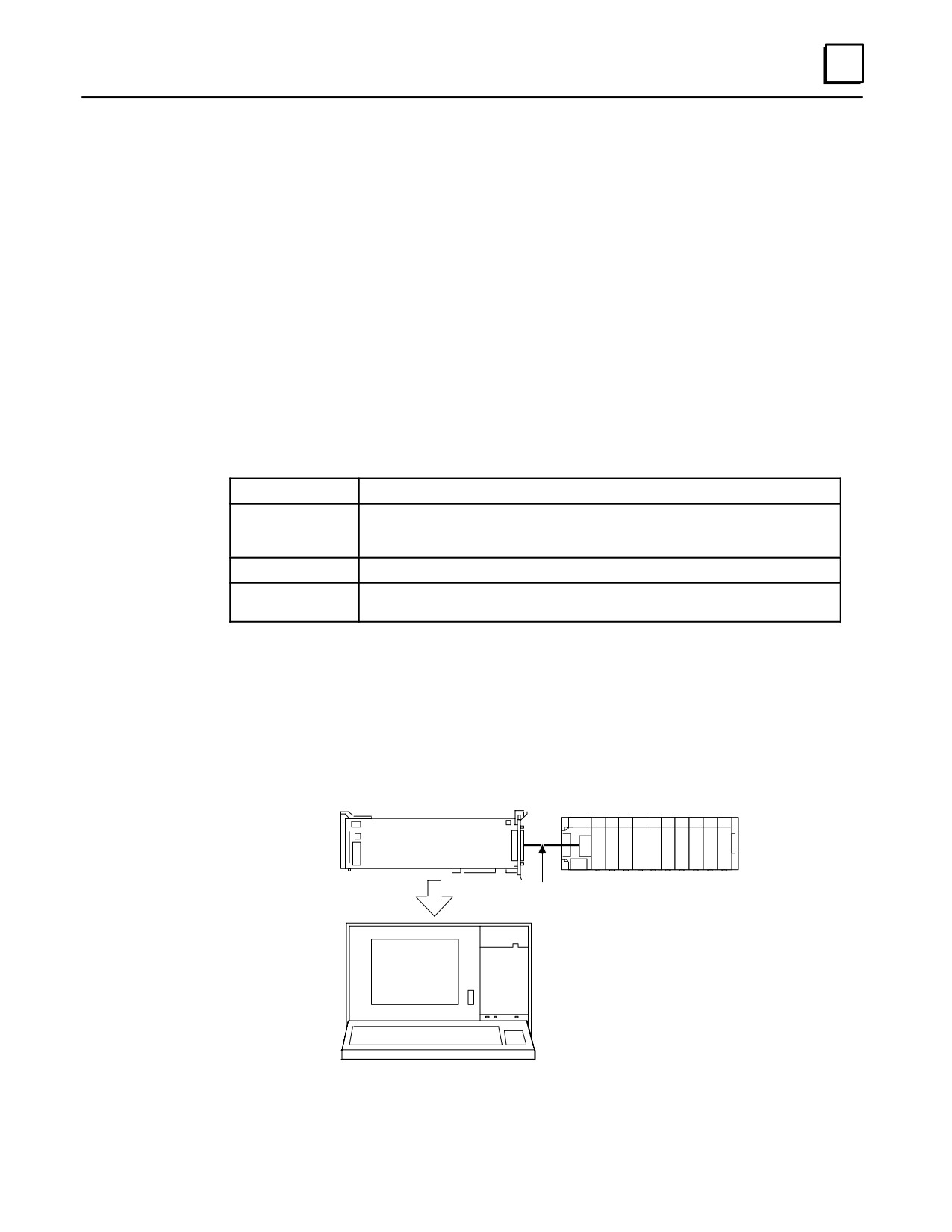
Workstation Interface to Series 90 CPU (SNP Port) Cable
(Includes Instructions on Building Custom Length Cables)
Function of cable
The serial Work Station Interface cable has a 15-pin D connector on one end and a
37-pin D connector on the other end. This cable connects the CPUs serial port to the
Work station Interface board installed in the programming computer through an
isolated shielded, twisted pair.
Cable Specifications
Cable Length
10 feet (3 meters)
Connectors
CPU Side
15-pin male, D-subminiature type with M3 screws and AMP hood 207908-4, or equivalent
Programmer Side
37-pin male, D-subminiature type with 4-40 screws and AMP hood 1-207908-0, or equivalent
Hardware Kit
AMP 207871-1. Kit includes two metric screws and two screw clips.
Cable Type
24 AWG (.21 mm2), 30V computer grade. Extra flexible construction recommended for short
lengths.
Connecting the Cable
Attach the 15-pin D connector to the serial connector on the PLC power supply on
the CPU baseplate.
Attach the 37-pin D connector to the 37-pin D connector on the Work Station
Interface board.
a43060
ÎÎÎÎÎÎÎ
WSI
Î
Î
Î
Î
ÎÎÎÎ
SERIAL
Î
Î
Î
Î
ÎÎÎÎ
SERIES 90-30
SERIAL
CABLE
ÎÎÎÎ
ÎÎÎÎ
ÎÎÎÎÎ
ÎÎÎÎÎÎÎ
ÎÎÎÎÎÎÎÎÎ
ÎÎÎÎÎÎÎÎÎ
PROGRAMMER
Figure 10-1. Serial Port to Work Station Interface Board Cable Connection
GFK-0356P
Chapter 10 Cables
10-9
10
Building Custom Length Cables
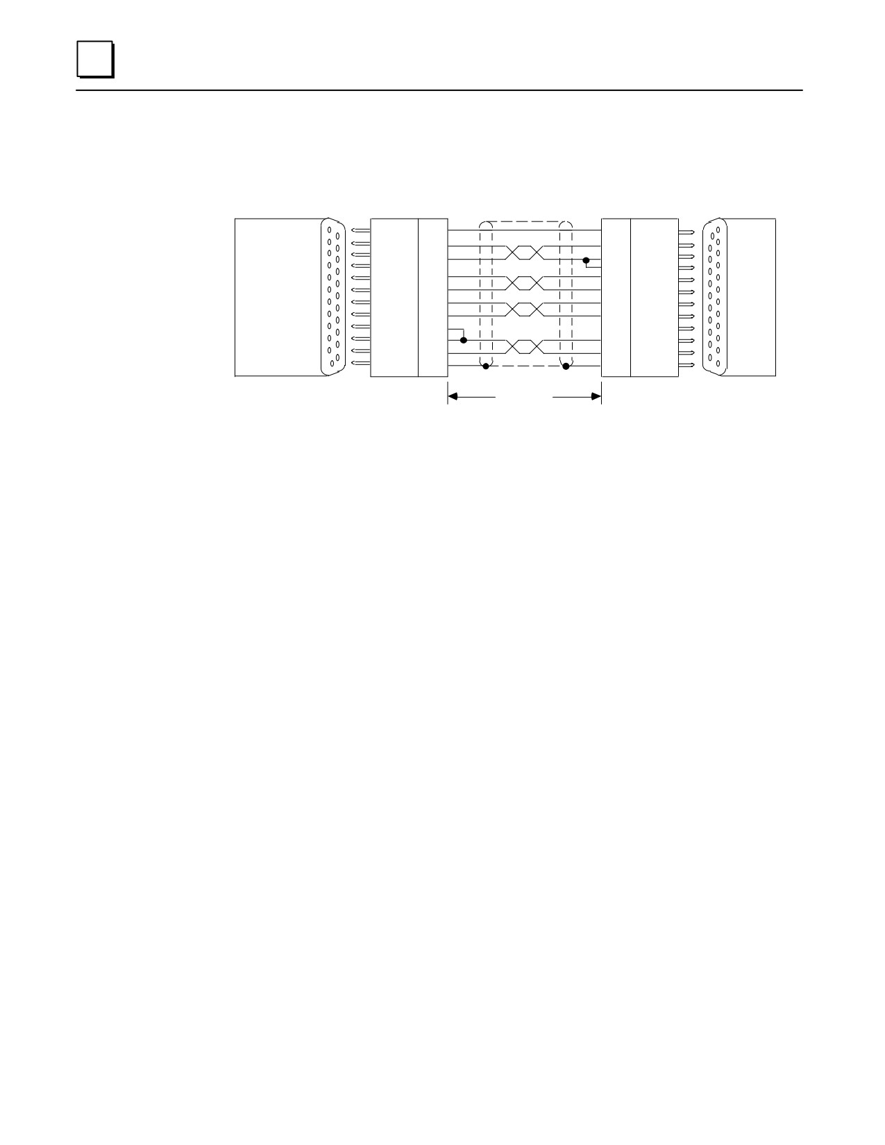
The following information is provided for those users who may want to build a serial
cable with a different length for connecting a Series 90 PLC to a Workmaster II computer.
PIN
PIN
a43114
ÎÎ
Î
Î
ÎÎ
0V
1
7
0V
ÎÎ
SD (B)
26
11
RD (B’)
Î
SD (A)
27
10
RD (A’)
WORKSTATION
SERIES
ÎÎ
9
RT
Î
INTERFACE
CTS (A)
30
14
RTS (B)
90-70
ÎÎ
CTS (B)
31
6
RTS (A)
Î
(CPU)
(WS9A1)
RTS (B)
32
8
CTS (B’)
ÎÎ
Î
SERIES
RTS (A)
33
15
CTS (A’)
RT
36
90-30
ÎÎ
Î
RD (B)
34
13
SD (B)
(PS)
ÎÎ
RD (A)
35
12
SD (A)
Î
SHLD
37
1
SHLD
ÎÎ
4000 FEET
ÎÎ
37- PIN
37- PIN
(1200 METERS)
15- PIN
15- PIN
FEMALE
MALE
MAXIMUM
MALE
FEMALE
D-TYPE
D-TYPE
D-TYPE
D-TYPE
CONNECTOR
CONNECTOR
CONNECTOR
CONNECTOR
Figure 10-2. Series 90 PLC to Workmaster II Serial Cable
Cable Type - 24 AWG (.22 mm2), 30V computer grade. Extra flexible construction
recommended for short lengths.
Connectors - 37-pin male D-type with 4-40 screws and AMP hood No. 1-207908-0
or equivalent. 15-pin male D-type with M3 screws and AMP hood No. 207908-4, or
equivalent. An AMP connector is not supplied with M3 (metric) screws.
Hardware Kit - AMP 207871-1. This kit includes two metric screws, and two screw
clips.
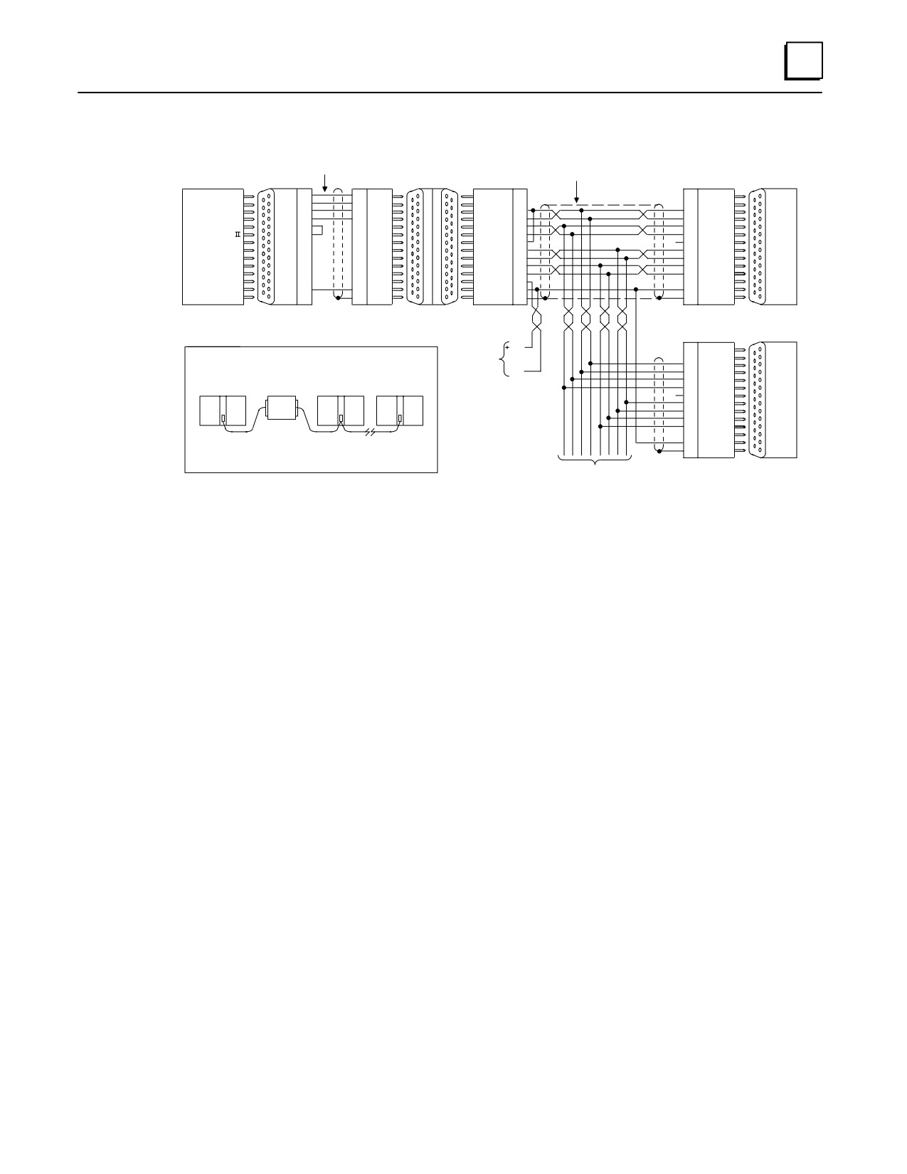
Multidrop Configuration, Workmaster II to Series 90 PLCs
The following illustrations show the wiring diagram and requirements for connecting a
Workmaster II, Workmaster, or compatible computer to Series 90 PLCs in an 8-wire
multidrop, serial data configuration.
The figure below is an example of the wiring configuration required for the multidrop
configuration when using the RS-422/RS-485 to RS-232 converter.
Note
The connector to the PLC serial port in the Series 90-30 PLC must be a
right angle connector in order for the hinged door to close properly.
10-10
Series 90-30 PLC Installation and Hardware Manual - October 1999
GFK-0356P
10
IC690CBL705 OR EQUIVALENT
RS-232/RS-422
RS-422
RS-232 SHIELDED PAIRS
CONVERTER
MAKE CONNECTIONS
a44511
(IC690ACC900)
INSIDE D-CONNECTORS
SLAVE
PIN
PIN
PIN
PIN
STATION
TD
2
3
RD
DCD ( A )
2
2
Î
RD
3
2
TD
ÎÎ
Î
DCD ( B )
3
3
Î
RTS
4
5
CTS
RD ( A’ )
10
12
SD ( A )
SERIES
CTS
5
20
DTR
RD ( B’ )
11
13
SD ( B )
90-70
Î
DCD
8
8
DCD
ÎÎÎ
SD ( A )
12
10
RD ( A’ )
Î
WORKMASTER
DTR
20
SD ( B )
13
11
RD ( B’ )
CPU
RT
9
9
RD
RS-422
RS-232
Î
ÎÎ
Î
CTS ( A’ )
15
6
RTS ( A )
Î
PORT
PORT
CTS ( B’ )
8
14
RTS ( B )
RTS ( A )
6
15
CTS ( A’ )
Î
ÎÎ
Î
RTS ( B )
14
8
CTS ( B’ )
Î
+5V
5
5
+5V
GND
7
7
GND
0V
7
7
0V
Î
1
SHLD
ÎÎÎ
SHLD
1
1
SHLD
Î
25- PIN
25- PIN
25- PIN
25-PIN
15-PIN
15- PIN
15- PIN
15- PIN
MALE
FEMALE
MALE
FEMALE
FEMALE
MALE
MALE
FEMALE
RS-232
RS-422
LAST
PORT
PORT
PIN
STATION
POWER
5V
2
NOTE
SOURCE
3
WHEN WIRING RS-422 /485 MULTIDROP CABLES REFLECTIONS ON THE
FOR
12
SD ( A )
Î
SERIES
TRANSMISSION LINE CAN BE REDUCED BY CONFIGURING THE CABLE IN A
CONVERTER
0V
13
SD ( B )
90-30
DAISY CHAIN FASHION AS SHOWN BELOW.
10
RD ( A’ )
MASTER
CONVERTER SLAVE STATION
LAST STATION
11
RD ( B’ )
Î
PS
PLC 15-PIN CONNECTOR
9
RD
RS-422
SERIES 90-30 LOCATED
6
RTS ( A )
PORT
ÎÎ
ON POWER SUPPLY
14
RTS ( B )
Î
15
CTS ( A’ )
SERIES 90-70 LOCATED
ON THE CPU BOARD
8
CTS ( B’ )
ÎÎ
5
+5V
Î
ALSO IT IS RECOMMENDED TO MAKE ANY NECESSARY CONNECTIONS
7
0V
INSIDE THE CABLE CONNECTOR TO BE MOUNTED ON THE PLC. IT IS
1
SHLD
NOT RECOMMENDED TO USE TERMINAL STRIPS TO OTHER TYPES OF
Î
CONNECTORS ALONG THE LENGTH OF THE TRANSMISSION LINE.
15- PIN
15- PIN
TO OTHER PLC’s
MALE
FEMALE
* TERMINATION RESISTANCE FOR THE RECEIVE DATA (RD) SIGNAL NEEDS TO BE CONNECTED ONLY ON UNITS AT THE END OF THE LINES. THIS TERMINATION IS MADE
ON THE SERIES 90 PLC PRODUCTS BY CONNECTING A JUMPER BETWEEN PIN 9 AND PIN 10 INSIDE THE 15-PIN D-SHELL WITH THE FOLLOWING EXCEPTION. FOR SERIES
90-70 PLCs, CATALOG NUMBERS IC697CPU731 AND IC697CPU771, THE TERMINATION FOR RD AT THE PLC IS IMPLEMENTED BY A JUMPER BETWEEN PIN 9 AND PIN 11.
GROUND POTENTIAL: MULTIPLE UNITS, NOT CONNECTED TO THE SAME POWER SOURCE, MUST HAVE COMMON GROUND POTENTIALS OR GROUND ISOLATION FOR PROPER
OPERATION OF THIS SYSTEM.
Figure 10-3. Example of Multidrop Configuration with Converter
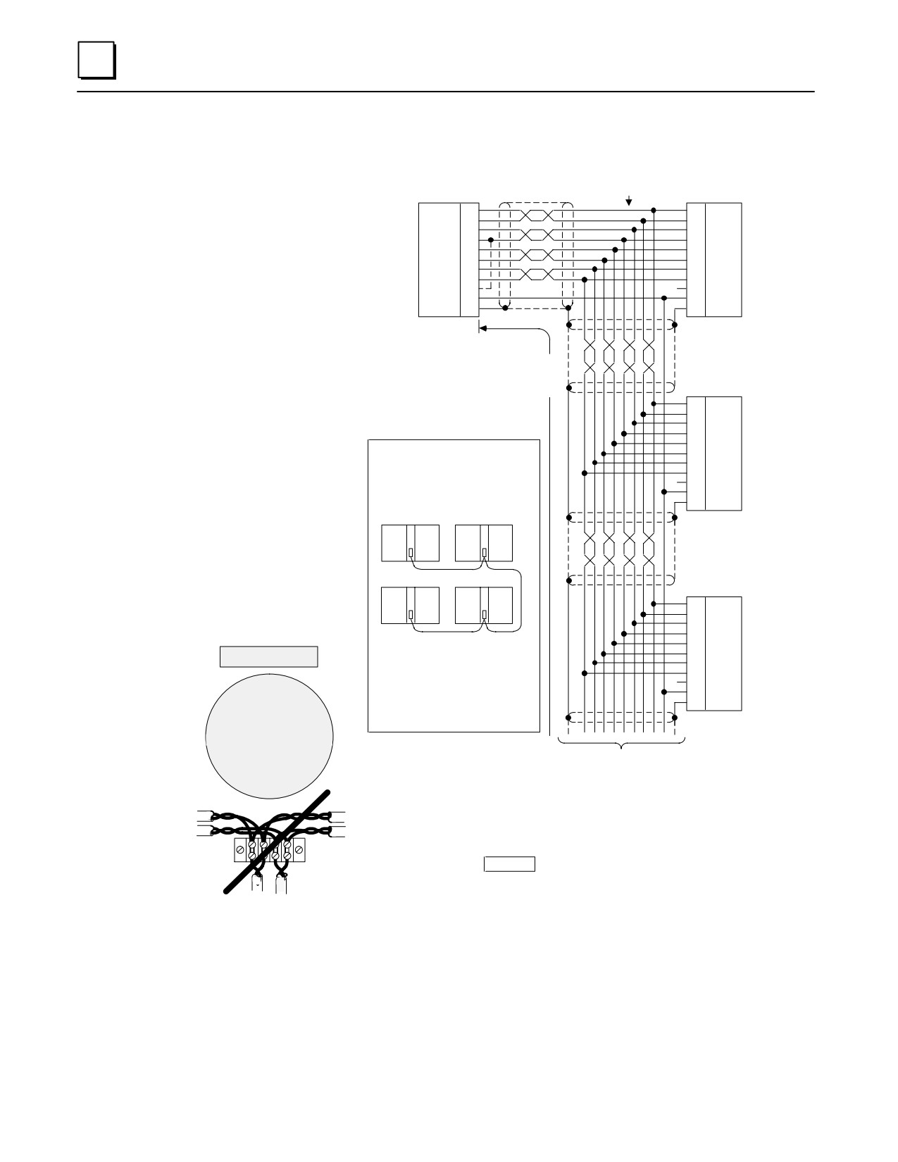
The following figure is an example of the wiring configuration required when a Work
Station Interface board is installed in the computer. The 15-pin serial port connector for
the 90-30 PLC is on the power supply; the 37-pin serial port connector for Workmaster II
and Workmaster computers is on the Work Station Interface board in the programming
computer. The cable type for these connections should be 24 AWG (.22 mm2), 30V
computer grade. Extra flexible construction is recommended for short lengths.
GFK-0356P
Chapter 10 Cables
10-11
10
WORKMASTER OR
a43846
WORKMASTER II
SHIELDED
MAKE CONNECTIONS
SERIES
WSI
TWISTED
INSIDE D-CONNECTORS
90 PLC
PIN
PAIRS
PIN
SD (A)
27
10
RD (A’)
SD (B)
26
11
RD (B’)
RD (A’)
35
12
SD (A)
RD (B’)
34
13
SD (B)
CTS (A’)
31
6
RTS (A)
CTS (B’)
30
14
RTS (B)
RTS (A)
33
15
CTS (A’)
RTS (B)
32
8
CTS (B’)
RT
36
9
RT
0V
1
7
0V
SHIELD
37
1
SHIELD
37-PIN
15-PIN
CONNECTOR
CONNECTOR
UP TO A
MAXIMUM OF
SERIES
4,000 FEET
90 PLC
(1,200 METERS)
PIN
10
RD (A’)
11
RD (B’)
12
SD (A)
13
SD (B)
6
RTS (A)
NOTE
14
RTS (B)
WHEN WIRING RS-422/485 MULTIDROP
15
CTS (A’)
CABLES, REFLECTIONS ON THE TRANS-
8
CTS (B’)
MISSION LINE CAN BE REDUCED BY CON-
9
RT
FIGURING THE CABLE IN A DAISY CHAIN
7
0V
FASHION AS SHOWN BELOW.
1
SHIELD
WORKMASTER
PLC 1
15-PIN
CONNECTOR
SERIES
PLC 3
PLC 2
90 PLC
PIN
10
RD (A’)
11
RD (B’)
12
SD (A)
13
SD (B)
6
RTS (A)
ALSO IT IS RECOMMENDED TO MAKE ANY
14
RTS (B)
IMPORTANT !
NECESSARY CONNECTIONS INSIDE THE
15
CTS (A’)
CABLE CONNECTOR TO BE MOUNTED ON
8
CTS (B’)
THE PLC.
9
RT
7
0V
IT IS NOT RECOMMENDED TO USE TERMI-
DO NOT
1
SHIELD
NAL STRIPS OR OTHER TYPES OF CON-
USE TERMINAL STRIPS
NECTORS ALONG THE LENGTH OF THE
OR OTHER TYPES OF
15-PIN
TRANSMISSION LINE.
CONNECTOR
CONNECTORS ALONG THE
LENGTH OF THE TRANSMISSION
LINE WHEN WIRING A
TO OTHER PLC’s
MULTIDROP SERIAL DATA
(MAXIMUM OF 8 PLC’s ON A MULTIDROP)
CONFIGURATION
TERMINATION RESISTANCE FOR THE RECEIVE DATA (RD) SIGNAL NEEDS TO BE CON-
NECTED ONLY ON UNITS AT THE END OF THE LINES. THIS TERMINATION IS MADE ON
THE SERIES 90 PLC PRODUCTS BY CONNECTING A JUMPER BETWEEN PIN 9 AND PIN 10
INSIDE THE 15-PIN D-SHELL, WITH THE FOLLOWING EXCEPTION. FOR SERIES 90-70 PLCs,
ÎÎ
Î
CATALOG NUMBERS IC697CPU731 AND IC697CPU771, THE TERMINATION FOR
RD AT THE PLC IS IMPLEMENTED BY A JUMPER BETWEEN PIN 9 AND PIN 11.
ÎÎ
Î
*
CAUTION
GROUND POTENTIAL: MULTIPLE UNITS, NOT CONNECTED TO THE SAME POWER
ÎÎ
SOURCE, MUST HAVE GROUND POTENTIAL WITHIN " 7V FOR PROPER OPERATION
OF THIS SYSTEM. FAILURE TO PROVIDE A COMMON GROUND MAY CAUSE DAMAGE
TO PLC COMPONENTS.
Figure 10-4. Series 90 PLC to Programmer 8-Wire Multidrop, Serial Data Configuration
10-12
Series 90-30 PLC Installation and Hardware Manual - October 1999
GFK-0356P