FANUC Series 90-30 PLC. Installation and Hardware Manual (GFK-0356P) - page 6
Chapter
Input and Output Modules
7
The basics of the Series 90-30 Input and Output (I/O) modules are covered in this
chapter for your convenience. A table listing these modules is located at the end of this
chapter. For detailed specifications and installation instructions, please refer to
publication GFK-0898, Series 90-30 PLC I/O Module Specifications. This chapter also
contains a preliminary description of the IC693DVM300 Digital Valve Driver Module.
Basic I/O Module Types
Discrete Input
Series 90-30 discrete input modules convert AC and DC power levels from user
devices to the logic levels required by the PLC. An optical coupler provides
isolation between the incoming power and the logic circuitry. Discrete input
modules are available that have 8, 16, or 32 points.
Discrete Output
Series 90-30 discrete output modules convert logic levels into AC or DC power
levels required for driving user supplied devices. Either a power semiconductor
or an electromagnetic relay switches each output point. The discrete output
semiconductor-switched modules are available with 5, 8, 12, 16, or 32 output
points. Relay output modules are available with either 8 or 16 Normally Open
relay contact outputs.
Discrete Input/Output
Combination discrete input/output modules combine AC inputs and relay
outputs or DC inputs and relay outputs on one module. Each of these modules
have 8 input circuits and 8 relay output circuits on one board.
Analog Input
Series 90-30 analog input modules provide A/D (Analog to Digital) conversion by
converting an analog input signal into a scaled digital number which will be
transferred into the PLC’s %AI memory. Analog input modules are provided in
four versions, (1) a 4-channel current module, (2) a 4-channel voltage module,
(3) a 16-channel high-density current input module, and (4) a 16-channel
high-density voltage input module.
Analog Output
Series 90-30 analog output modules provide D/A (Digital to Analog) conversion
by converting a scaled digital number (from the PLC’s %AQ memory) into an
analog output voltage. Analog output modules are provided in three versions,
(1) a 2-channel current module, (2) a 2-channel voltage module, and (3) a
high-density current/voltage module with 8 analog output channels.
7-1
GFK-0356P
7
Analog Combination Module
An analog combination module provides 4 A/D input channels and 2 D/A output
channels on one module. Each of the input and output channels can be
configured individually for current or voltage mode.
Third-Party Modules
In addition to the modules discussed in this chapter, numerous third-party I/O
modules (and other hardware and software products) for the Series 90-30 PLC
are available to meet a wide variety of needs. Third-party companies that meet
GE Fanuc’s standards may apply for recognition under the GE Fanuc
Accompany Program. Details on this program are found in the GE Fanuc
Automation Solutions Catalog, or on the GE Fanuc web site, both listed below.
For information on third-party modules, consult the following:
Your GE Fanuc PLC distributor or sales engineer
The GE Fanuc web site at http://www.gefanuc.com
The GE Fanuc Automation Solutions Catalog, GFW-0067
7-2
Series 90-30 PLC Installation and Hardware Manual - October 1999
GFK-0356P
7
Discrete I/O Modules
Discrete I/O Module Point Density
There are two density categories for these modules:
Standard Density Modules: Standard density modules have up to 16
circuits (also called “points”) per module. These modules are equipped with
a removeable terminal board. See the following figure.
High Density Modules: High density modules have 32 circuits per module.
These modules have either a 50-pin connector, or two 24-pin connectors
mounted on their faceplates. Connection choices are discussed later in this
chapter.
Standard Density Discrete I/O Module Features
Standard Density(16 points or less) Modules have the following features (refer to the
following figure):
Removeable Terminal Board. You can remove the terminal board from the module
in order to wire it, if desired. Then, when you are finished wiring it, you can easily
reinstall it on the module. However, some prefer to leave it on the module when
wiring. If you ever need to replace a module, you don’t have to do any rewiring if
your old terminal board is still in good condition. Simply remove the wired terminal
board from the old module and install it on the new module. The terminal board
screw terminals are also convenient points for measuring voltages while testing or
troubleshooting.
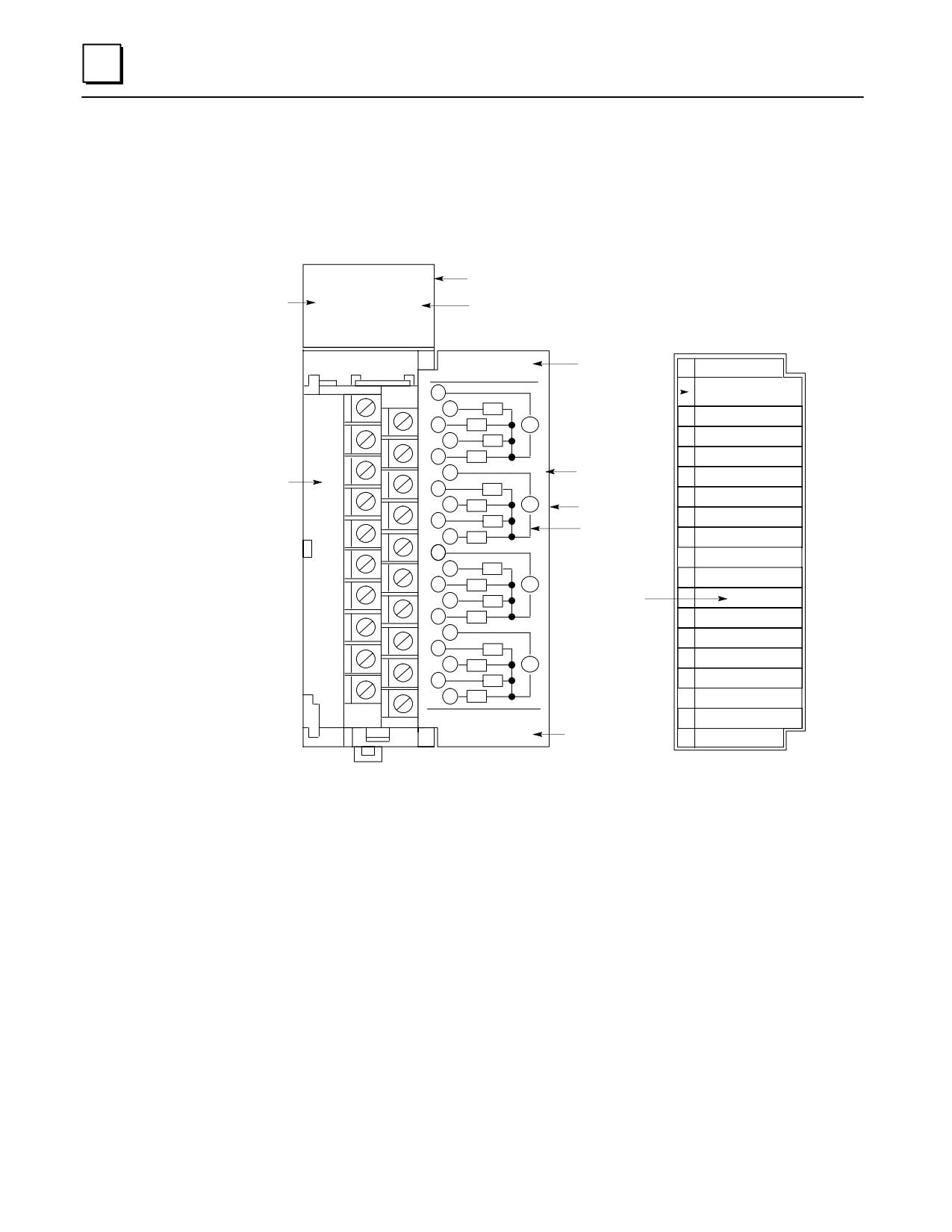
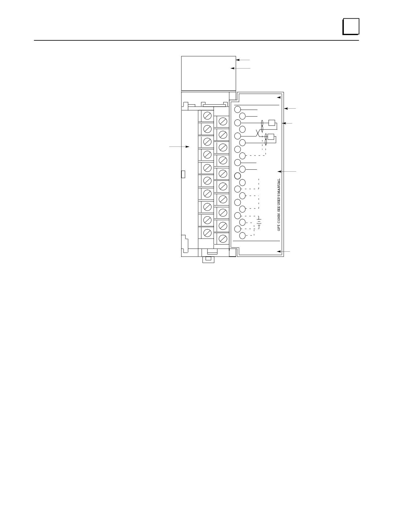
Hinged Front Cover. The cover is easily opened to access the terminal board
connections. Normally it’s kept closed to protect personnel from accidentally
touching a hot terminal. Note in the following figure that the back side of the front
cover insert contains a schematic diagram of the terminal board connections. The
module catalog number (IC693MDL940 in the example shown) is printed on the
bottom of the front cover insert. The module catalog number is also printed on the
label on the side of the module. However, in order to see this side label, the module
has to be removed from the PLC
On the front side of the front cover insert are lines that correspond to the module’s
I/O points. You can temporarily remove the insert and write the signal name for
each point on the appropriate line, as shown in the example in the figure.
Also on the front side of the front cover insert, running vertically on the left edge of
the insert, is a color bar that identifies the type of module: Blue = DC, Red = AC,
and Gray = Analog.
Module Lens Cap. Located on the top front of the module, it covers the LED (Light
Emitting Diode) status lights . These are labeled in the following figure in two
groups, A1 through A8, and B1 through B8. Since this is a figure of a 16-Point
Output module, there are 16 LED status lights. (The number of status lights on any
given module is a function of the number of circuits points on that module.) If you
compare these status lights to the connection diagram on the back of the hinged
cover, you will notice that the outputs on this module are in two groups, labeled
A1-A8 and B1-B8, that correspond to the A and B rows of status LEDs. Note the
additional LED on the right side of the lens cap that is labeled with the letter F. This
GFK-0356P
Chapter 7 Input and Output Modules
7-3
7
is a blown fuse indicator light. This letter F is present on all of the discrete I/O
module lens caps, but is only functional on certain Output Modules that have
internal fuses. It only lights if an internal fuse is blown. A table with a list of
modules having fuses as well as other details about the status LEDs is provided in
Chapter 13 of this manual.
a43082A
Lens Cap
A1 2 3 4 5 6 7 8
STATUS
F
Fuse Indicator LED
LEDs
B1 2 3 4 5 6 7 8
Hinged Cover
Front View
ÎÎÎÎÎ
ÎÎÎÎÎÎ
OUTPUT
Module Type
ÎRELAY N.O.2 AMP
ÎÎÎOUTPUTÎÎ
1
Color Bar
Indicates Type
ÎÎ
2
ÎA1ÎÎ
ÎÎRELAY N.O. 2 AMP
Î
of Module
A1
Pilot Light 1
Î3ÎA2ÎÎVÎ
ÎÎÎÎÎÎÎ
A2
Pilot Light 2
4
ÎÎ
5
A4 A3ÎÎ
ÎÎÎÎÎÎA3
Control ON
Î
Removable
Î6ÎÎÎÎ
ÎÎÎÎÎÎA4
Emargency Stop
Î
Removable
Insert
Terminal
Pump 1 ON
Board
8
A6
Î7ÎÎA5ÎÎVÎ
HInged Cover
ÎÎÎÎÎÎA5
Î
Pump 2 ON
Î9ÎÎA7ÎÎÎ
Connection
Î
Î
10
Diagram on
Motor Starter 1
11
ÎÎA8ÎÎÎ
Back of Insert
ÎA7ÎÎÎÎÎÎ
A8
MotorStarter 2
Î12ÎB1ÎÎÎ
Î
B1
ÎÎÎÎÎ
CR 1
Î
Î1314B2ÎÎVÎ
B3
User can Write
ÎÎÎÎÎÎB2
CR 2
Î
Signal Names on
CR 3
Î15ÎB4ÎÎÎ
Front of Insert
ÎÎÎÎÎÎB3
Î
16
CR 4
Î17ÎÎÎÎÎ
B5
Î
Î
SOL 1
Î18B6ÎÎVÎ
Î
Î
B6
SOL 2
B8
Î1920ÎB7ÎÎ
Î
B7
ÎÎÎÎÎ
SOL 3
Î
ÎÎ44A726782-015Î
ÎÎÎÎÎÎB8 S
OL 4
Î
FOR USE WITH
ÎÎIC693MDL940Î
ÎÎÎÎÎÎÎ
ÎÎÎÎÎ
ÎÎÎÎÎÎ
Figure 7-1. Example of Series 90-30 Standard Density Discrete Output Module
7-4
Series 90-30 PLC Installation and Hardware Manual - October 1999
GFK-0356P
7
Wiring Standard Density (16-Point or Less) Discrete Modules
There are three basic wiring methods:
Direct Method. Run the wires from the field devices (switches, relays, etc.)
directly to the screws on the modules’ terminal boards.
Terminal Strip Method. Mount a terminal strip inside the control enclosure
and wire from the terminal strip to the modules’ terminal boards. Then
wire field devices to the terminal strip.
Terminal Block Quick Connect Assembly Method. The Terminal Block
Quick Connect Assembly has three pieces: a faceplate, a cable, and a
terminal block. The faceplate snaps onto an I/O module in place of its
normal terminal board. This faceplate has a connector that mates with the
cable. In turn, the cable plugs into a connector on the terminal block. The
terminal block mounts on a DIN-rail in a convenient place in your enclosure.
The terminal block is used for connecting to field devices such as switches
and relays. This method saves, on the average, over two hours of wiring
time per module when compared with the Terminal Strip method. For
more information, see Appendix J, “Terminal Block Quick Connect
Components.”
Discrete Relay Output Module Protection
Output points on discrete relay output modules that switch an inductive load such as a
relay coil, lamp filament, or solenoid coil should have external protection. This is usually
in the form of an R-C (Resistor-Capacitor) network across an AC load, or a reverse-biased
diode across a DC load. Please see GFK-0898, Series 90-30 PLC I/O Module Specifications,
for details.
GFK-0356P
Chapter 7 Input and Output Modules
7-5
7
High Density (32-Point) Discrete Module Features
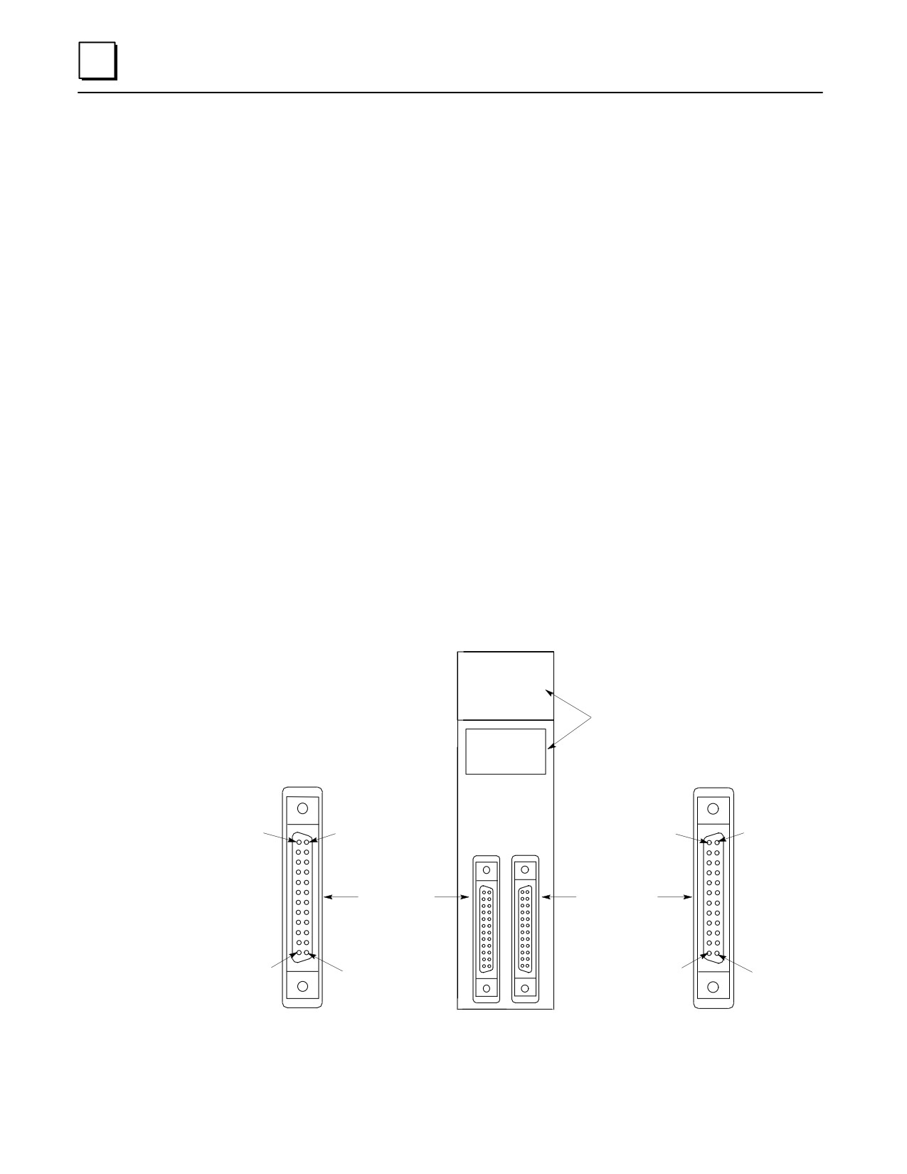
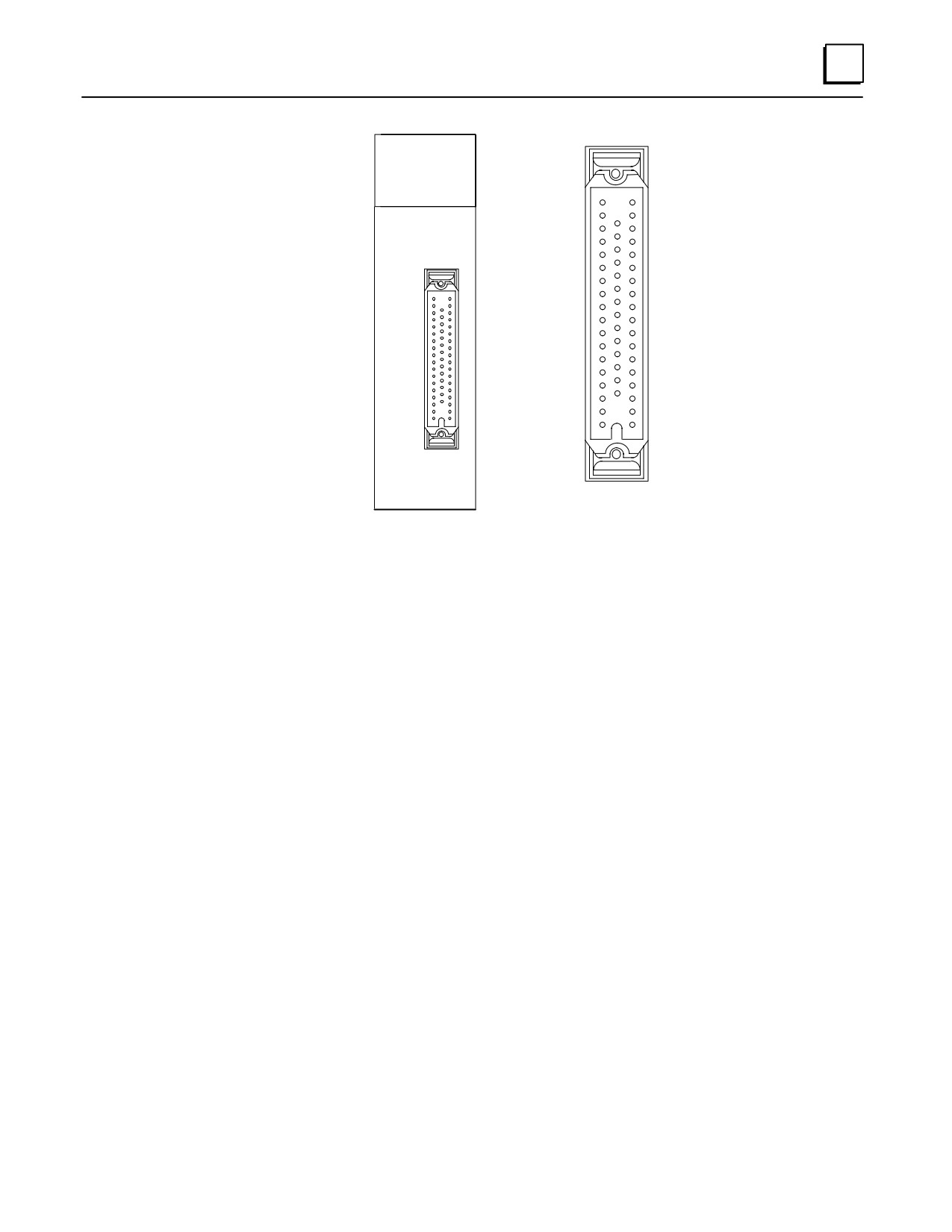
There are two types of these modules. One type has a single 50-pin
connector on its faceplate, the other type has a pair of 24-pin connectors on
its faceplate (see next two figures).
The dual 24-pin type has LED status indicators. The 50-pin type does not.
The LED status indicators are arranged in four groups of eight across,
labeled A, B, C, and D. They are located at the top of the module (see next
figure).
32-point modules are only available in 5, 12, and 24 VDC ratings.
None of the 32-point modules are fused.
These modules are useful in applications where a high count of DC I/O
points is required. The maximum number of I/O points for a Series 90-30
system can be obtained by using a CPU that supports a total of eight 10-slot
racks, and by populating the racks with 32-point modules. The theoretical
maximum number of I/O points possible is calculated by adding the 9
available slots in the CPU rack (the CPU must occupy one slot) to the 70 slots
in the seven 10-slot expansion or remote racks to get a total of 79 slots.
Multiply 79 times 32 for a maximum of 2,528 I/O points (only CPUs 350 -
364 support this many I/O points). Of course, this assumes that every slot is
populated with a 32-point I/O module. Most practical applications require
that you use some slots for option modules, so the number of slots available
for I/O modules will be reduced accordingly.
A1 2 3 4 5 6 7 8
F
B1 2 3 4 5 6 7 8
LED Indicators
C1 2 3 4 5 6 7 8
D1 2 3 4 5 6 7 8
INPUT
5/12 VDC
POS/NEG LOGIC
3.0 mA/Pt at 5VDC
Pin B12
Pin A12
8.5 mA/Pt at 12VDC
Pin A1
Pin B1
CD
AB
Left Side
Right Side
Connector
Connector
Pin B1
Pin A1
Pin A12
Pin B12
Figure 7-2. Example of 32-Point I/O Module (IC693MDL654) With Dual Connectors
7-6
Series 90-30 PLC Installation and Hardware Manual - October 1999
GFK-0356P
7
33
1
19
INPUT 32 PT
24 VDC ISOL
NEG/POS LOGIC
32
50
18
7.5 mA/Pt
Connector Pin
Numbering
Figure 7-3. Example of 32-Point I/O Module (IC693MDL653) With Single Connector
GFK-0356P
Chapter 7 Input and Output Modules
7-7
7
Wiring Methods for 32-Point Discrete I/O Modules
Modules with Single 50-Pin Connector
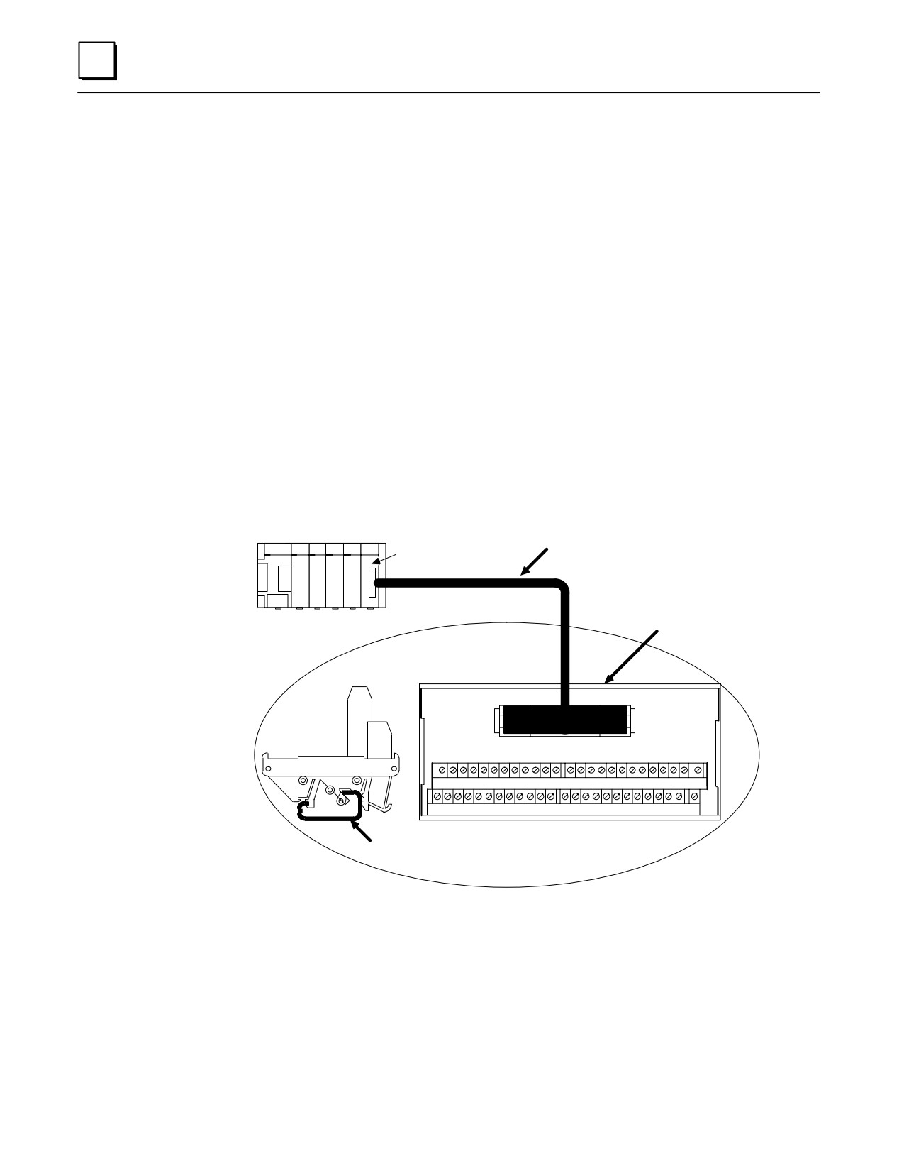
Three choices are available for connecting these modules.
Connect to a Weidmuller #912263 terminal block using one of the two GE
Fanuc “extension” cables (see next figure). Cable IC693CBL306 is 3 feet
(1meter) long. Cable IC693CBL307 is 6 feet (2 meters) long. Chapter 10,
“Cables,” has details on these cables.
Connect to a user-supplied terminal block/strip or I/O field devices using
one of the two GE Fanuc “interface” cables. These cables have a 50-pin
connector on one end that plugs into the module, and stripped, tinned leads
on the other for wiring to a terminal block/strip or I/O field devices. Cable
IC693CBL308 is 3 feet (1 meter) long, and cable IC693CBL309 is 6 feet (2
meters) long. These cables are useful if you have to run your wiring
through conduit that is too small for a connector to fit through.
Build a custom length cable. This is required if you need a cable longer than
6 feet (2 meters). See the IC693CBL308/309 data sheet in Chapter 10 for
pin-out details.
IC693CBL306/307
ÎÎÎÎÎÎ
50-Pin, 32-Point
Extension Cable
I/O Module
a44838A
ÎÎÎÎÎÎ
ÎÎÎÎÎÎ
Weidmuller 912263
Terminal Block
Series 90-30 PLC
ÎÎÎÎÎÎ
50
ÎÎÎÎÎÎÎ
End
Î
Î
View
1
26 27
28
29 30 31 32 33 34 35 36 37
38 39 40 41 42 43 44 45 46 47 48 49
50
ÎÎÎ
1
2
3
4
5
6
7
8
9
10
11 12
13 14
15 16 17 18 19
20
21 22 23 24
25
Î Î
Top
Mounts on
View
DIN-Rail
Figure 7-4.
50-PIN, 32 Point I/O Module Connection Method
7-8
Series 90-30 PLC Installation and Hardware Manual - October 1999
GFK-0356P
7
Modules with Dual 24-Pin Connectors
Three choices are available for connecting these modules
Connect to a pair of Terminal Block Quick Connect (TBQC) terminal blocks
(IC693ACC337) using a pair of GE Fanuc cables. Three lengths of cables are
available: 20” (0.5 meter), 3 feet (1 meter), 6 feet (2 meters). The cables come
in right hand and left hand types because the connectors on the modules are
oriented differently (see figure 7-2). For details on the terminal blocks and
cables, please see Appendix J.
Connect to user supplied terminal block/strip or directly to I/O field devices
using a pair of 10 foot (3 meter) GE Fanuc interface cables. These cables
have 24-pin connectors on one end for connecting to the module, and
stripped, tinned leads on the other for wiring to a terminalblock/striporI/O
devices. Cable IC693CBL327 is for the left side and IC693CBL328 is for the
right side. These cables are useful if you have to run your wiring through
conduit that is too small for a connector to fit through, or if you need a cable
longer than six feet. Chapter 10, “Cables,” has details on these cables.
Build a custom length cable. This is required if you need a cable longer than
10 feet (3 meters). See the IC693CBL327/328 data sheet in Chapter 10 for
details on building custom length cables.
GFK-0356P
Chapter 7 Input and Output Modules
7-9
7
Analog Module Features
Analog Modules have the following basic features (refer to the following figure):
Removeable Terminal Board. You can remove the terminal board from the module
in order to wire it, if desired. Then, when you are finished wiring it, you can easily
reinstall it on the module. However, some prefer to leave it on the module when
wiring. If you ever need to replace a module, you don’t have to do any rewiring if
your old terminal board is still in good condition. Simply remove the wired terminal
board from the old module and install it on the new module if it is good condition.
The terminal board screw terminals are also convenient points for measuring
voltages while testing or troubleshooting.
Hinged Front Cover. The cover is easily opened to access the terminal board
connections. For normal operation, it is kept closed to protect personnel from
accidentally touching a hot terminal. Note in the following figure that the back side
of the front cover insert contains a schematic diagram of the terminal board
connections. The module catalog number (IC693ALG391 in this example) is printed
on the bottom of the front cover insert. The module catalog number is also printed
on the label on the side of the module. However, in order to see this side label, the
module has to be removed from the PLC
On the front side of the front cover insert are lines that correspond to the module’s
I/O points. You can temporarily remove the insert and write the signal name for
each point on the appropriate line to aid in testing or troubleshooting.
Also on the front side of the front cover insert, running vertically on the left edge of
the insert, is a colored line that identifies the type of module: Blue = DC, Red = AC,
and Gray = Analog.
Module Lens Cap. Located on the top front of the module, it covers the LED (Light
Emitting Diode) OK status light. This light indicates the basic status of the module.
For normal operation, the OK LED should be on.
7-10
Series 90-30 PLC Installation and Hardware Manual - October 1999
GFK-0356P
7
Lens Cap
a43082B
OK
Module OK LED
Module Type
ÎÎÎOUTPUTÎÎÎ
ANALOG
Î1VOUT1RENTÎÎÎ
Hinged Cover
VOUT2 ÎÎÎ
2
ÎÎ
IOUT1
3
1
Removeable Insert
ÎÎ
4
IOUT2ÎÎÎÎ
RTN1ÎÎ2ÎÎ
ÎÎ
RTN2
Removeable Terminal Board
ÎÎ6GNDÎÎÎÎ
7
GND
ÎÎ8ÎÎÎÎÎ
JMPV1
9
ÎÎ10JMPV2ÎÎÎÎ
Connection Diagram
Î11ÎDEF0ÎÎÎ
ÎÎ12ÎÎ*ÎÎÎ
13
ÎÎ14Î0CH1AÎÎÎ
Î1516ÎÎÎÎÎ
Î17ÎÎ*+ÎÎÎ
24V
19
ÎÎ18ÎÎÎÎÎ
ÎÎ20ÎC0-20mAÎÎ*Î
ÎÎ4FOR USE WITH01Î
Module Catalog No.
ÎIC693ALG391ÎÎ
Figure 7-5. Example of Series 90-30 Analog Current Output Module
Wiring Methods for Analog Modules
Twisted, shielded instrumentation cable is strongly recommended for analog module
input or output signal connections. Proper grounding of the shield is also important.
For maximum electrical noise suppression, the cable shield should only be grounded at
one end of the cable. For Input modules, ground the end that is in the noisiest
environment (which often is at the field device end). For Output modules, ground at the
module end. See GFK-0898, Series 90-30 PLC I/O Module Specifications, for more shield
grounding information.
Analog Input Module Wiring Methods
Correcting electrical noise problems can sometimes be a trial-and-error routine.
However, in general, it is generally best to ground the cable shield as close to the source
of the noise as possible, which is usually at the device end. In troubleshooting noise
problems, sometimes it is beneficial to experiment with the shield grounding point
location. Remember, the cable shield should be grounded at one end only. Also, it is best
to keep the length of stripped cable leads as short as possible to minimize the length of
unshielded conductors that will be exposed to the noisy environment. See the Series
90-30 PLC I/O Module Specifications Manual, GFK-0898 for additional details.
Direct Method. Run a shielded cable from the field device (transducer,
potentiometer, etc.) directly to the module. Connect the conductors to the
GFK-0356P
Chapter 7 Input and Output Modules
7-11
7
applicable screws on the module’s terminal board. Ground the shield at the
field device end, exposing a minimum amount of conductor to the noisy
environment. Do not connect the shield at the module end (insulate it with
shrink tubing).
Terminal Strip Method. Mount a terminal strip inside the control enclosure
and run a shielded cable from the terminal strip to the module’s terminal
board terminals. Connect the shield to the metal panel next to the terminal
strip. Do do not connect the shield at the module end (insulate it with
shrink tubing). Wire the field device to the terminal strip with a shielded
cable, grounding the shield at the device end only (insulate the other end of
the shield with shrink tubing). Also, keep the length of exposed leads at the
terminal strip and device ends as short as possible.
Note
TBQC - The Terminal Block Quick Connect Assembly is not
recommended for use with analog modules due to cable shielding
requirements.
Analog Output Module Wiring
Each output should be connected using a good quality shielded wire with the shield
grounded at the module end only. See GFK-0898, Series 90-30 PLC I/O Module
Specifications, for more information.
I/O Module Power Supply Current Draw
These values are found in Chapter 12 of this manual, which discusses how to calculate
power supply loading. The information is also found in GFK-0898, Series 90-30 PLC I/O
Module Specifications.
I/O Module Wire Routing
To reduce noise coupling among PLC wires, it is recommended you keep electrically
noisy wiring, such as AC power wiring and Discrete Output Module wiring, physically
separated from low-level signal wiring such as connections to DC and Analog Input
modules. This can be accomplished by grouping separately, where practical, the
following categories of wiring:
AC power wiring. This includes the AC input to the PLC power supply, as
well as other AC devices in the control cabinet.
Analog Input and Output Module wiring. This should also be shielded to
further reduce noise coupling.
Discrete Output Module wiring. These often switch inductive loads that
produce noise spikes when switched off.
DC Input Module wiring. Although suppressed internally, these low-level
inputs should be further protected against noise coupling by observing
these wiring practices.
7-12
Series 90-30 PLC Installation and Hardware Manual - October 1999
GFK-0356P
7
Grouping Modules to Keep Wires Segregated
If practical, grouping similar modules together in the PLC racks can help keep wiring
segregated. For example, one rack could contain only AC modules and a different rack
only DC modules, with further grouping in each rack by input and output types. For
smaller systems, as an example, the left end of a rack could contain Analog modules, the
middle could contain DC modules, and the right end could contain AC modules. Where
AC or Output wiring bundles must pass near low-level signal wiring bundles, avoid
running them beside each other. Route them so that, if they have to cross, they do so at
a right angle. This will minimize coupling between them.
GFK-0356P
Chapter 7 Input and Output Modules
7-13
7
IC693DVM300 Digital Valve Driver Module
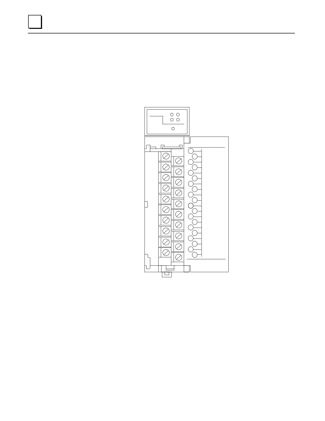
This 4-channel digital valve driver module is capable of driving loads of up to 1.6 Amps
at 24 VDC. Although it mounts in a standard Series 90-30 PLC slot, it does not connect to
the PLC backplane. Its control power and output power come from an external supply.
(The GE Fanuc IC690PWR124 stand-alone power supply would be a suitable choice.)
This module is designed for TTL (5 Vdc) inputs.
DIG CH:
1
3
2
4
PWR
ÎÎÎÎÎ
OUTPUT
ÎÎ28V 1.6A max.Î
Î1ÎÎ+28V.INÎÎ
2
+28V.RET
Î3ÎÎAUX.OUT.+15Î
Î4ÎAUX.OUT.-15Î
5
DIGITAL.1.IN
Î6ÎDIGITAL.2.INÎ
Î7ÎÎDIGITAL.3.INÎ
8
DIGITAL.4.IN
Î9ÎÎDIGITAL.RETÎ
10
ÎÎÎ+28V1.INÎÎ
11
+28V2.IN
Î12Î28V1&2.RETÎ
Î13ÎÎVALVE.1.OUTÎ
14
VALVE.1.RET
Î15ÎÎVALVE.2.OUTÎ
Î16ÎVALVE.2.RETÎ
17
VALVE.3.OUT
Î18ÎVALVE.3.RETÎ
Î19ÎÎVALVE.4.OUTÎ
20
VALVE.4.RET
ÎÎÎÎÎÎ
ÎÎÎÎÎÎ
ÎÎÎÎÎ
Figure 7-6. IC693DVM300 Digital Valve Driver Module
Indicator LEDs
DIG CH: 1 - 4: These light when their corresponding input is at a Logic 1 level.
PWR: Lights to indicate the presence of +26 VDC (nominal) input power on
terminals 1 and 2.
7-14
Series 90-30 PLC Installation and Hardware Manual - October 1999
GFK-0356P

7
DVM Specifications
Table 7-1. IC693DVM300 Specifications
OUTPUT CHARACTERISTICS
Outputs (Channels) per Module
4
Isolation
2500 Vrms (optical isolation)
Nominal Output Voltage
24 Vdc
Power Supply for Output Channels
26 Vdc nominal, 21 Vdc minimum, 35 Vdc
maximum
Output Current
1.6 Amps maximum per channel
6.4 Amps maximum total per module
Output Voltage Drop (fully loaded)
0.32 Vdc
Off state leakage current
26 µA at 26 Vdc operating voltage
Turn-on response time
< 1 µS with resistive load
Turn-off response time
< 1 µS with resistive load
Output protection (per channel)
Reversed-biased zener diode for
free-wheeling inductive current. Also 36
Volt transorb for ESD and surge
protection.
INPUT CHARACTERISTICS
Input Voltage
5 VDC (TTL) nominal, 12Vdc Maximum
Logic 1 Level
Logic 1: V > 3.5 Vdc
Logic 0: V < 0.7 Vdc
Input Current
3.8 mA nominal
Input protection
13.3 Volt transorb
AUXILIARY POWER SUPPLY OUTPUTS
Voltage and Current
+15 VDC @ 0.3A and -15 VDC @ 0.2A
Isolation
Not isolated
MODULE POWER REQUIREMENTS
Power Consumption (Does not consume
5.6 Watts (with all outputs on) from
any power from PLC backplane.)
external supply connected to terminals 1
and 2 (does not include power consumed
by outputs)
Input Voltage
+26 VDC nominal, 35 VDC maximum
continuous
Fuses
Quantity 1 - Module control power. 1 Amp. Buss GDB-1A.
Quantity 4 - One for each output. 2 Amps. Littlefuse 239002.
GFK-0356P
Chapter 7 Input and Output Modules
7-15
7
DVM Connections
Table 7-2. IC693DVM300 Connections
Pin
Signal Name
Connection Description
No.
1
+28V.IN
Module Control Power + input terminal (common on pin 2).
Supplies power to module’s signal-level circuits and auxiliary
+15 and -15 Volt power supplies (pins 2, 3, and 4). Requires
external 26 VDC (nominal) power supply
2
+28V.RET
Common terminal for Module Control Power (pin 1).
3
AUX.OUT.+1
+ 15 Vdc @ 0.3A Auxiliary power output for external circuits.
5
Not isolated. Developed from input power on pins 1 and 2.
4
AUT.XOUT.-1
- 15 Vdc @ 0.2A Auxiliary power output for external circuits.
5
Not isolated. Developed from input power on pins 1 and 2.
5
DIGITAL.1.IN
Channel 1 TTL input connection (common on pin 9)
6
DIGITAL.2.IN
Channel 2 TTL input connection (common on pin 9)
7
DIGITAL.3.IN
Channel 3 TTL input connection (common on pin 9)
8
DIGITAL.4.IN
Channel 4 TTL input connection (common on pin 9)
9
DIGITAL.RET
Common connection for Digital Input Channels 1 - 4 (pins 5 -
8)
10
+28V1.IN
Power Supply connection for Output Channels 1 and 2
(common on pin 12). Required external 26 VDC (nominal)
power supply.
11
+28V2.IN
Power Supply connection for Output Channels 3 and 4
(common on pin 12). Required external 26 VDC (nominal)
power supply.
12
28V1&2.RET
Common connection for both Output Channel Power Supply
inputs (pins 10 and 11)
13
VALVE1.OUT
Channel 1 Output connection (return on pin 14)
14
VALVE1.RET
Return connection for Channel 1 Output (pin 13)
15
VALVE2.OUT
Channel 2 Output connection (return on pin 16)
16
VALVE2.RET
Return connection for Channel 2 Output (pin 15)
17
VALVE3.OUT
Channel 3 Output connection (return on pin 18)
18
VALVE3.RET
Return connection for Channel 3 Output (pin 17)
19
VALVE4.OUT
Channel 4 Output connection (return on pin 20)
20
VALVE4.RET
Return connection for Channel 4 Output (pin 19)
7-16
Series 90-30 PLC Installation and Hardware Manual - October 1999
GFK-0356P

7
Table 7-3. Series 90-30 Discrete I/O Modules
Catalog Number
Points
Description
Discrete Modules - Input
IC693MDL230
8
120 VAC Isolated
IC693MDL231
8
240 VAC Isolated
IC693MDL240
16
120 VAC
IC693MDL241
16
24 VAC
IC693MDL630
8
24 VDC PositiveLogic
IC693MDL632
8
125 VDC Positive/NegativL ogic
IC693MDL633
8
24 VDC Negative Logic
IC693MDL634
8
24 VDC Positive/Negative
IC693MDL640
16
24 VDC PositiveLogic
IC693MDL641
16
24 VDC Negative Logic
IC693MDL643
16
24 VDC Positive Logic, FAST
IC693MDL644
16
24 VDC Negative Logic, FAST
IC693MDL645
16
24 VDC Positive/NegativL ogic
IC693MDL646
16
24 VDC Positive/NegativeLogicFAST
IC693MDL652
32
24 VDC Positive/NegativL ogic
IC693MDL653
32
24 VDC Positive/NegativeLogic,FAST
IC693MDL654
32
5/12 VDC (TTL) Positive/NegativL ogic
IC693MDL655
32
24 VDC Positive/NegativL ogic
IC693ACC300
16
Input Simulator
DiscreteModules -Output
IC693MDL310
12
120 VAC, 0.5A
IC693MDL330
8
120/240VAC, 2A
IC693MDL340
16
120 VAC, 0.5A
IC693MDL390
5
120/240VAC Isolated, 2A
IC693MDL730
8
12/24VDCPositive Logic, 2A
IC693MDL731
8
12/24VDCNegativeLogic, 2A
IC693MDL732
8
12/24VDCPositive Logic, 0.5A
IC693MDL733
8
12/24VDCNegativeLogic
IC693MDL734
6
125 VDC Positive/Negative Logic, 1A
IC693MDL740
16
12/24VDCPositive Logic, 0.5A
IC693MDL741
16
12/24VDCNegativeLogic, 0.5A
IC693MDL742
16
12/24VDCPos. Logic, Electronic Short Circuit Protect
IC693MDL750
32
12/24VDCNegativeLogic
IC693MDL751
32
12/24VDCPositiveLogic
IC693MDL752
32
5/24 VDC (TTL)Negative Logic
IC693MDL753
32
12/24VDCPositive/Negative Logic, 0.5A
IC693MDL930
8
Relay, 4A Isolated
IC693MDL940
16
Relay, 2A
IC693MDL931
8
Relay, Isolated, N.C. and Form C, 8A
IC693DVM300
4
Digital Valve Driver module, 1.6A, 24 VDC
DiscreteModules-CombinationInput/Output
IC693MAR590
8/8
120 VAC Input, Relay Output
IC693MDR390
8/8
24 VDC Input, Relay Output
Table 7-4. Series 90-30 Analog I/O Modules
Catalog Number
Channels
Description
AnalogModules
IC693ALG220
4
Analog Input, Voltage
IC693ALG221
4
Analog Input, Current
IC693ALG222
16
Analog Input, Voltage, High Density
IC693ALG223
16
Analog Input, Current, High Density
IC693ALG390
2
Analog Output, Voltage
IC693ALG391
2
Analog Output, Current
IC693ALG392
8
Analog Output, Current/Voltage, High Density
IC693ALG442
4 In/2Out
Analog Current/VoltageCombinationInput/Output
GFK-0356P
Chapter 7 Input and Output Modules
7-17
Chapter
Option Modules
8
This chapter provides an overview of Series 90-30 Option modules. For detailed
information, the applicable user ’s manual should be consulted (these manuals are listed
for each module at the end of its section).
Third-Party Option Modules and the Accompany Program
In addition to the modules discussed in this chapter, numerous third-party option
modules (and other hardware and software products) for the Series 90-30 PLC are
available to meet a wide variety of needs. Third-party companies that meet GE Fanuc’s
standards may apply for recognition under the GE Fanuc Accompany Program. Details
on the Accompany Program are found in the GE Fanuc Automation Solutions Catalog or
on the GE Fanuc web site, both listed below. For information on third-party modules,
consult the following:
Your GE Fanuc PLC distributor or sales engineer
The GE Fanuc web site at http://www.gefanuc.com
The GE Fanuc Automation Solutions Catalog, GFW-0067
Option Modules Discussed in this Chapter
IC693CMM301 Genius Communications Module (GCM)
IC693CMM302 Enhanced Genius Communications Module (GCM+)
IC693BEM331 Genius Bus Controller (GBC)
IC693BEM340 FIP Bus Controller (FBC)
IC693BEM330 FIP Remote I/O Scanner
IC693APU301/302 Motion Mate Axis Positioning Module (APM)
IC693DSM302 Motion Mate Digital Servo Module (DSM302)
IC693DSM314 Motion Mate Digital Servo Module (DSM314) - Preliminary
IC693APU300 High Speed Counter (HSC) Module
IC693BEM320 I/O Link Interface Module
IC693BEM321 I/O Link Master Module
IC693APU305 I/O Processor Module
IC693CMM321 Ethernet Interface Module
IC693PCM300/301/31P rogrammable Coprocessor Module (PCM)
IC693CMM311 Communications Control Module (CCM)
IC693ADC311 Alphanumeric Display Coprocessor (ADC) Module
IC693TCM302 Temperature Control Module (TCM)
IC693PTM100 Power Transducer Module (PTM) -Preliminary
8-1
GFK-0356P
8
IC693CMM301 Genius Communications Module (GCM)
The Genius Communications Module (IC693CMM301) for the Series 90-30 PLC provides global
communications on a Genius Communications bus between Series 90-30 PLCs and/or other
GE Fanuc PLCs. Series 90-70, Series Six, and Series Five PLCs can communicate on this bus
through their respective Genius Bus Controllers.
The Genius Communications bus is a token passing peer-to-peer, noise immune network
optimized to provide high speed transfer of real time control data. Up to eight Series 90-30
PLC CPUs, in any combination, can communicate with each other over a single Genius I/O
serial bus using a standard twisted pair, shielded cable.
a45138
GENIUS
COMM
OK
COM
ÎÎCOMMUNICATIONSÎ
ÎÎ1ÎMODULEÎÎ
2
ÎÎ3ÎÎSER1ÎÎ
4
ÎÎ5ÎÎÎÎ
6
ÎÎ78ÎÎSERÎÎ
2
ÎÎ9ÎÎÎÎ
10
ÎÎ11ÎÎÎÎ
12
SHD
ÎÎ1314ÎÎINÎÎ
ÎÎ1516ÎÎÎÎ
ÎÎ1718ÎÎSHDÎÎ
OUT
ÎÎ1920ÎÎÎÎ
ÎÎ44FOR USE WITH02Î
IC693CMM301 / 302
ÎÎÎÎÎ
Figure 8-1. The IC693CMM301 GCM Module
Status LEDs
The LEDs on the front of the GCM module indicate its operating status and should be on
during normal operation.
OK Shows the status of the GCM module. This LED turns on after power up
diagnostics are completed.
COM Shows the status of the Genius communications bus. This LED is on steadily when
the bus is operating properly. It blinks for intermittent bus errors and is off for a
failed bus. It is also off when no configuration has been received from the PLC CPU.
8-2
Series 90-30 PLC Installation and Hardware Manual - October 1999
GFK-0356P
8
a43391
FIRST
LAST
DEVICE
DEVICE
SERIAL
SERIAL
S RIAL
ERIAL
ÎÎ
1
1
E1
S
1
ÎÎ
Î
Î
Î
R
SERIAL
SERIAL
SERIAL
SERIAL
R
2
2
2
2
ÎÎ
Î
Î
Î
ÎÎ
SHIELD
SHIELD
Î
SHIELD
S
HIELD
IN
IN
IN
IN
ÎÎ
Î
Î
Î
SHIELD
SHIELD
SHIELD
SHIELD
OUT
OUT
OUT
OUT
ÎÎ
Î
Î
Î
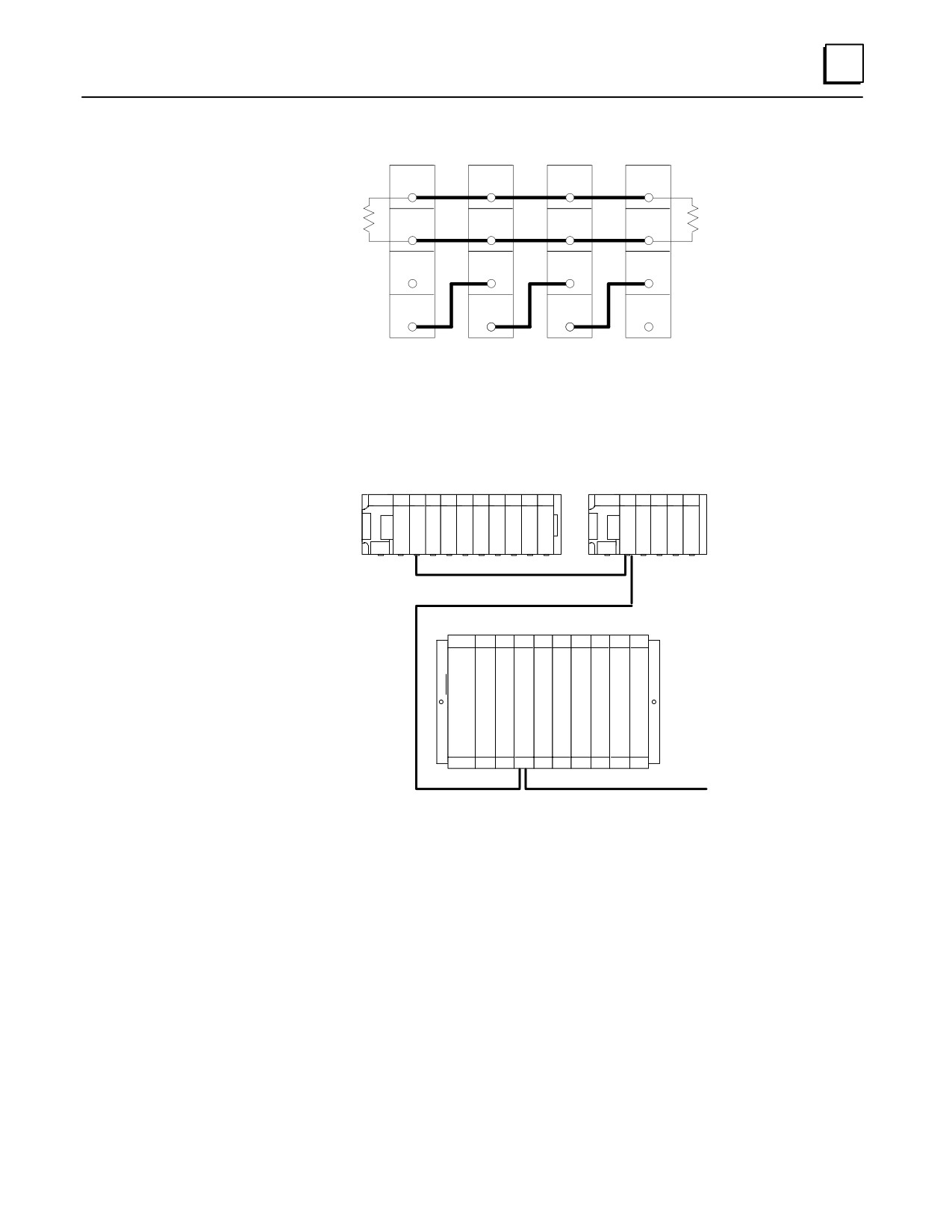
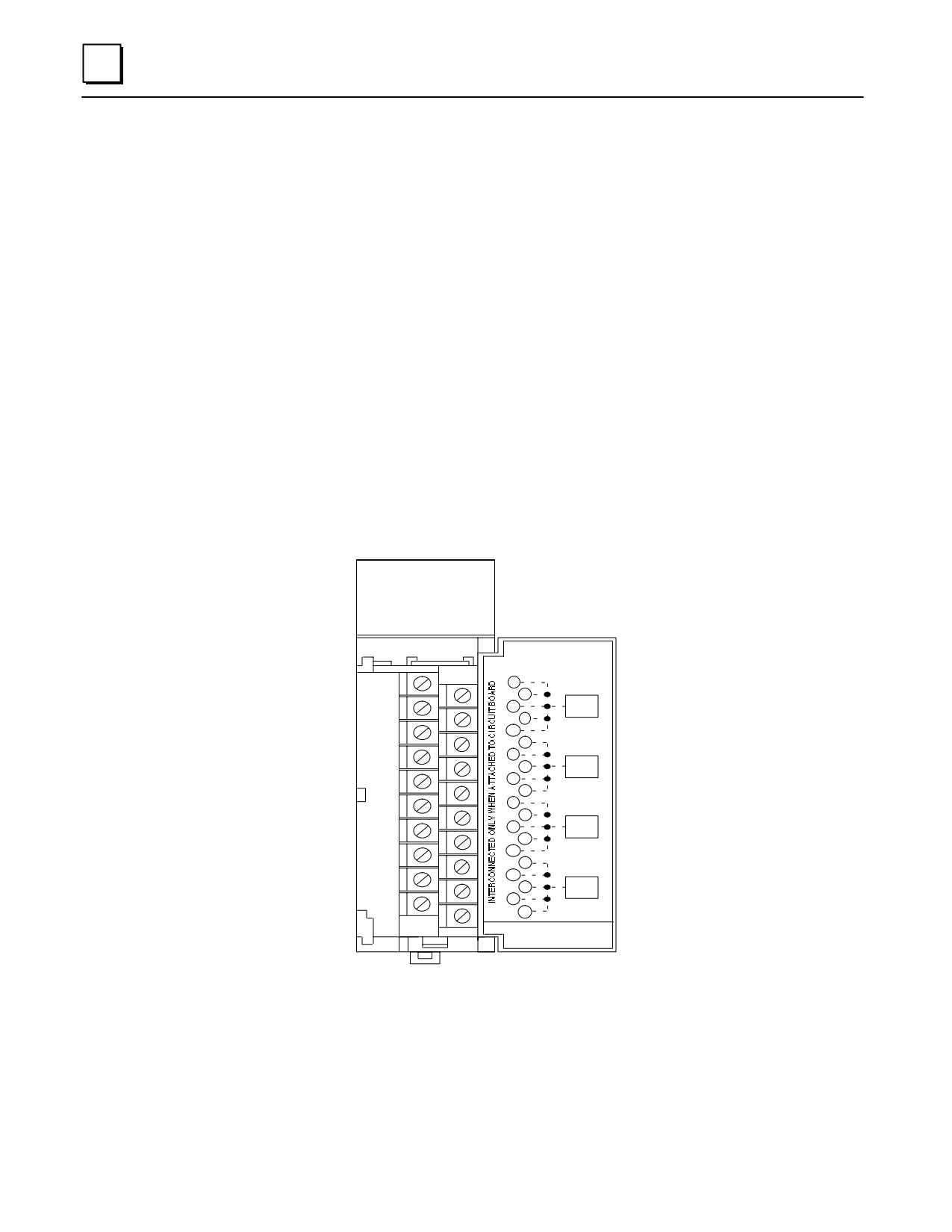
Figure 8-2. Genius Bus Wiring Schematic
a42915
SERIES 90-30
SERIES 90-30
ÎÎÎÎÎÎÎÎ
ÎÎÎÎÎ
C
G
G
Î
ÎP
C
ÎÎÎÎÎÎ
ÎÎ
C
ÎÎÎ
U
M
M
ÎÎÎÎÎÎÎÎ
ÎÎÎÎÎ
GENIUS COMMUNICATIONS BUS
SERIES 90-70
ÎÎÎÎÎÎÎÎÎ
G
ÎÎÎÎÎÎÎÎÎ
B
ÎÎÎÎÎÎÎÎÎÎ
ÎÎÎÎÎÎÎÎÎ
ÎÎÎÎÎÎÎÎÎ
ÎÎÎÎÎÎÎÎÎ
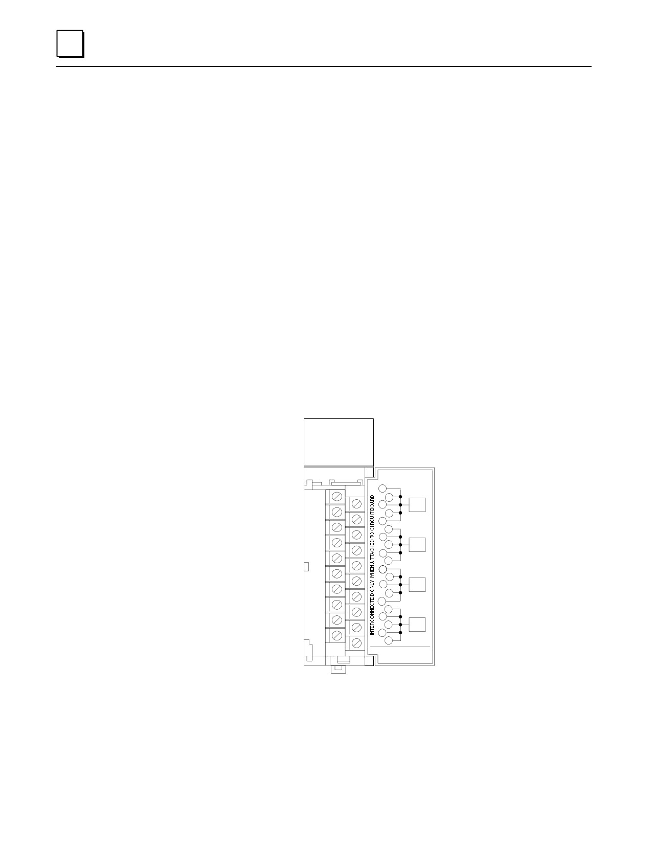
Figure 8-3. Example of Genius Communications Network
GCM Documentation
For detailed information on the Genius Communications Module, including installation
instructions, refer to GFK-0412, the Series 90-30 Genius Communications Module User’s
Manual.
GFK-0356P
Chapter 8 Option Modules
8-3
8
IC693CMM302 Enhanced Genius Communications Module (GCM+)
The Enhanced Genius Communications Module (GCM+), IC693CMM302, is an intelligent
module that provides automatic global data communications between a Series 90-30 PLC
and up to 31 other devices on a Genius bus.
The GCM+ can be located in any standard Series 90-30 CPU baseplate, expansion base-
plate, or remote baseplate. However, for most efficient operation, it is recommended that
the module be installed in the CPU baseplate since the sweep impact time of the GCM+
module depends on the model of PLC and the baseplate where it is located. Note: if a GCM
module is present in a system, GCM+ modules cannot be included in the system.
Multiple GCM+ modules can be installed in a Series 90-30 PLC system with each GCM+
having its own Genius bus serving up to 31 additional devices on the bus. For example, this
allows a Series 90-30 PLC with three GCM+ modules to exchange global data with as many
as 93 other Genius devices automatically. In addition to basic global data exchange, the
GCM+ module can be used for various applications such as:
Data monitoring by a personal computer or an industrial computer.
Monitoring data from Genius I/O blocks (although it cannot control Genius I/O
blocks).
Peer-to-peer communications among devices on the bus.
Master-slave communications among devices on the bus (emulates remote I/O).
The Genius bus connects to the terminal board on front of the GCM+ module.
a45138
ENHANCED
GENIUS
COMM
OK
COM
ÎÎCOMMUNICATIONSÎ
ÎÎ1ÎMODULEÎÎ
2
ÎÎ3ÎÎSER1ÎÎ
4
ÎÎ56ÎÎÎÎ
ÎÎ78ÎÎSERÎÎ
2
ÎÎ910ÎÎÎÎ
ÎÎ1112ÎÎÎ
SHD
ÎÎ1314ÎÎINÎÎ
ÎÎ1516ÎÎÎÎ
ÎÎ1718ÎÎSHDÎÎ
OUT
ÎÎ1920ÎÎÎÎ
ÎÎIC693CMM301 / 3022Î
ÎÎÎÎÎ
Figure 8-4. Enhanced Genius Communications Module
8-4
Series 90-30 PLC Installation and Hardware Manual - October 1999
GFK-0356P
8
Status LEDs
The LEDs on the front of the GBC indicate its operating status and should be on during
normal operation.
OK Shows the status of the GBC module. This LED turns on after power up
diagnostics are completed.
COM Shows the status of the Genius communications bus. This LED is on steadily when
the bus is operating properly. It blinks for intermittent bus errors and is off for a
failed bus. It is also off when no configuration has been received from the PLC CPU.
GCM+ Documentation
For more information about the GCM+, refer to GFK-0695, Series 90-30 Enhanced Genius
Communications Module User’s Guide.
GFK-0356P
Chapter 8 Option Modules
8-5
8
IC693BEM331 Genius Bus Controller (GBC)
The Series 90-30 Genius Bus Controller (GBC), catalog number IC693BEM331, provides
the interface between a Series 90-30 PLC and a Genius I/O serial bus. The GBC receives
and transmits control data of up to 128 bytes for up to 31 devices on the Genius I/O bus.
A Genius Bus Controller can serve:
Genius blocks, which provide an interface to a wide range of discrete, analog, and
special-purpose field devices. Note that the GCM and GCM+ modules, described
earlier, cannot control Genius blocks.
Remote Drops, which consist of Series 90-70 I/O racks interfaced to the bus through
Remote I/O Scanner modules. Each of these drops can have any mix of Series 90-70
discrete and analog I/O modules, providing up to 128 bytes of input data and 128
bytes of output data.
Field Control I/O Station, which consists of a Bus Interface Unit (BIU) and up to
eight additional Field Control modules. The BIU provides intelligent processing, I/O
scanning, and feature configuration for the I/O station.
Genius Hand-Held Monitor (HHM), which is a portable device that can also be
permanently mounted. The HHM provides a convenient operator interface for
block setup, data monitoring, and diagnostics.
Multiple hosts, for communications using datagrams and Global Data.
a47051
GENIUS
BUS
CONTROL
OK
COM
ÎÎÎGENIUSÎÎÎ
BUS
ÎÎÎCONTROLLERÎÎ
1
ÎÎÎ2ÎÎÎÎ
SER
3
ÎÎÎ4ÎÎ1ÎÎ
5
ÎÎÎ6ÎÎÎÎ
7
ÎÎÎ8ÎÎSERÎÎ
2
9
ÎÎ10ÎÎÎÎ
11
ÎÎ12ÎÎÎÎ
SHD
13
ÎÎ14ÎÎINÎÎ
15
ÎÎ16ÎÎÎÎ
17
ÎÎ18ÎÎSHDÎÎ
OUT
19
ÎÎ20ÎÎÎÎ
ÎÎ44FOR USE WITHÎÎ
IC693BEM331
ÎÎÎÎÎÎ
Figure 8-5. Genius Bus Controller Module
A bus may feature I/O control, enhanced by communications commands in the program.
Or, a bus can be used entirely for I/O control, with many I/O devices and no additional
communications. A bus can also be dedicated to CPU communications, with multiple
CPUs and no I/O devices. More complex systems can also be developed, with dual CPUs
and one or more additional CPUs for data monitoring.
8-6
Series 90-30 PLC Installation and Hardware Manual - October 1999
GFK-0356P
8
Number of Genius Bus Controllers
Up to eight Genius Bus Controllers or Enhanced Genius Communications Modules can
be included in a Series 90-30 PLC system that has release 5.0 or later Logicmaster 90-30
software, and release 5.0 or later CPU firmware. A GBC cannot be installed in a system
with a GCM.
The I/O devices on a bus may be Genius I/O blocks, or standard Series 90-70 I/O modules
in one or more remote drops. The total number of I/O circuits that can be served by one
Genius bus depends on the types of I/O devices that are used and the memory available
in the CPU.
Many Genius I/O blocks have both inputs and outputs on the same block. Blocks
configured in the Logicmaster 90-30 software as having both inputs and outputs will
occupy the identical number of references in both %I and %Q memory, regardless of the
block’s software configuration. Unused references cannot be assigned to other inputs or
outputs, and should not be used in the application program.
Status LEDs
The LEDs on the front of the GBC indicate its operating status and should be on during
normal operation.
OK Shows the status of the GBC module. This LED turns on after power up
diagnostics are completed.
COM Shows the status of the Genius communications bus. This LED is on steadily when
the bus is operating properly. It blinks for intermittent bus errors and is off for a
failed bus. It is also off when no configuration has been received from the PLC CPU.
Compatibility
Specific equipment or software versions required for compatibility with the GBC module
are listed below.
Series 90-30 PLC
CPU: The GBC module can be used with CPU models: IC693CPU311K, 321K, 331L or
later, or any version of the IC693CPU313, 323, 340, 341, 350, 351, 352, 360, 363, and 364.
The CPU firmware must be release 5.0 or later.
Logicmaster 90-30 software: rel. 5.0 (IC641SWP301L, 304J, 306F, 307F) or later is required.
Series Six PLC
To exchange global data with a Genius Bus Controller, the Series Six Bus Controller must
be catalog number IC660CBB902F/903F (firmware version 1.5), or later.
Genius Hand-Held Monitor
The Genius Hand-Held Monitor can be used to display the GBC bus address, its
software version, and the Series Six register address configured for global data. HHM
version IC660HHM501H (revision 4.5) or later is required. There is no Hand-Held
Monitor connector on the GBC module, but a Hand-Held Monitor can communicate
with the GBC while connected to any other device on the bus. Optionally, an additional
HHM mating connector can be installed on the bus near the GBC.
GFK-0356P
Chapter 8 Option Modules
8-7
8
Hand-Held Programmer
The GBC can be configured using a Series 90-30 Hand-Held Programmer
(IC693PRG300).
Genius I/O Blocks
Genius I/O blocks can be present on the same bus as the GBC. However, because the Bus
Controller is not compatible with older phase A blocks, they should not be installed on the
same bus.
Genius Bus
The Genius bus is a shielded twisted-pair wire, daisy-chained between devices, and
terminated at both ends. Proper cable selection is critical to successful operation of the
system. Suitable cable types are listed in GEK-90486-1, the Genius I/O System and
Communications User’s Manual.
Diagnostics
Genius blocks and other devices on the bus automatically report faults, alarms and
certain other predefined conditions to the PLC.
INPUTS AND FAULT MESSAGE
a43556
FROM BLOCK 3
GBC
1
2
3
4
TOKEN
F
F
F FAULT
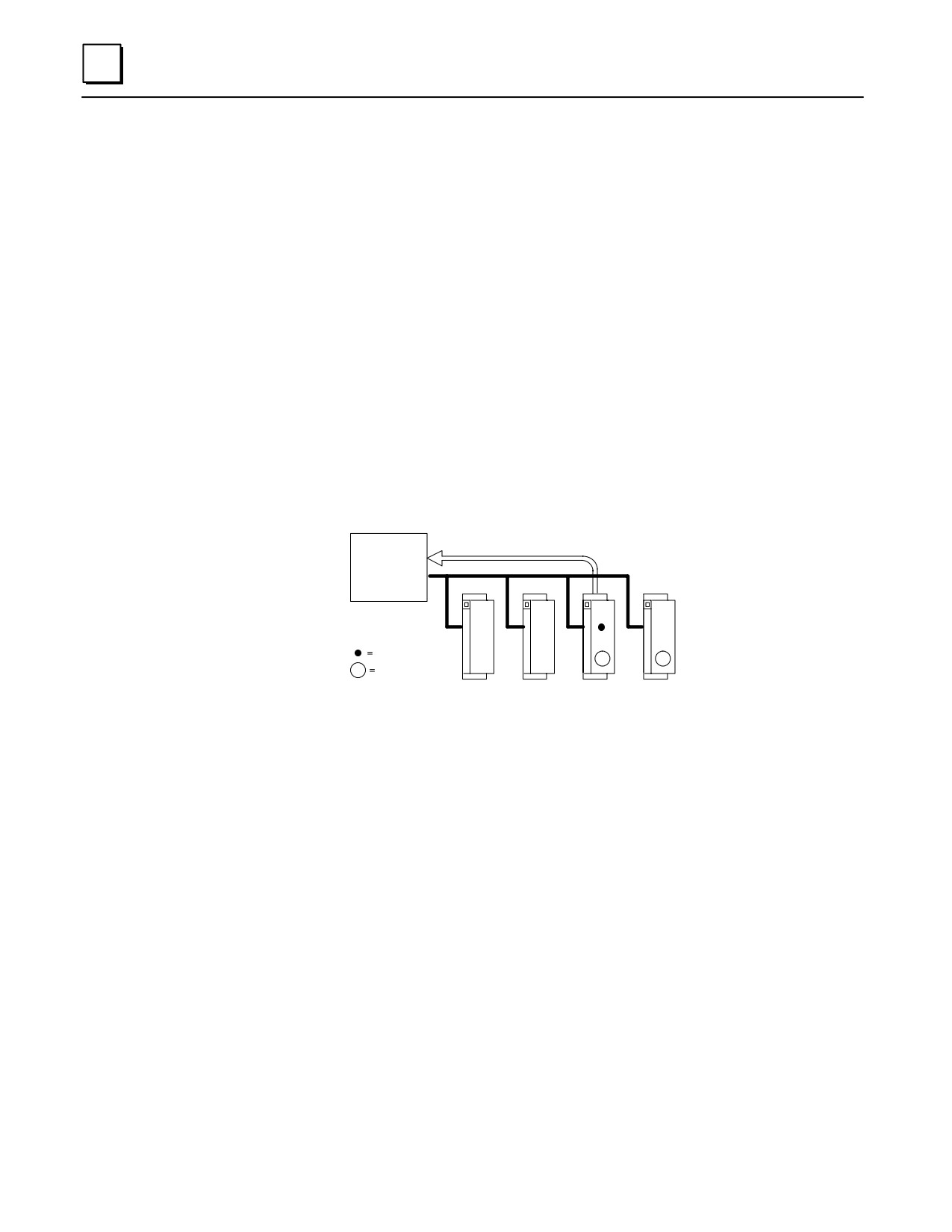
Only one diagnostic message can be sent during any bus scan. If a fault message has
already been sent (by another device) during that scan, a device saves its own diagnostic
message until the next available bus scan. For example, if the communications token is
currently at device 3, and faults occur at devices 3 and 4 at the same time, device 3 can
send its diagnostic message if another message has not already been sent. Device 4 must
wait at least one more bus scan to send its diagnostic message.
The GBC stores any diagnostic messages it receives. They are read automatically by the
Series 90-30 CPU. Faults can then be displayed in the fault table using the Logicmaster
90-30 software. A Genius Hand-held Monitor must be used to clear the faults from the
fault table.
Datagrams
The Series 90-30 GBC supports all Genius datagrams. Refer to chapter 3 of the Genius
I/O System and Communications User’s Manual, GEK-90486-1, for details on using
datagrams.
Global Data
Global Data is data that is automatically and repeatedly broadcast by a GBC. The Series
90-30 GBC can send up to 128 bytes of Global Data each bus scan. It can receive up to
128 bytes of Global Data each bus scan from each GBC on its bus.
8-8
Series 90-30 PLC Installation and Hardware Manual - October 1999
GFK-0356P

8
Sending Global Data
Once set up by configuration, Global Data is broadcast automatically. Other devices that
receive the Global Data sent by a Series 90-30 PLC place it in these memory locations:
Series 90-30 PLC Sends
Global Data To:
Other CPU Places Global Data in these Memory Location:
Series 90-30 PLC
%I, %Q, %G, %R, %AI, %AQ. Memory type and beginning
address are chosen during configuration of the receiving GBC.
Series 90-30 GCM+
%I, %Q, %G, %R, %AI, %AQ
Series90-30PLC/GCM
%G memory location corresponding to Device Number (16-23)
of the Series 90-30 GBC that sent the data.
Series Six PLC
Registermemory. Beginning Series Six address selected during
configuration of the Series 90-30 GBC that sent the data.
Series Five PLC
Registermemory. Beginning Series Five address selected during
configuration of the Series 90-30 GBC that sent the data.
Computer
PCIM or QBIM Input Table Segment corresponding to Device
Number of the Series 90-30 GBC that sent the data.
Receiving Global Data
The GBC can be configured to receive or ignore Global Data from any other GBC. The
memory type and length for incoming Global Data are also selected during
configuration. The Series 90-30 CPU can place incoming Global Data in %I, %Q, %G,
%R, %AI, or %AQ memory.
Genius Bus Controller Documentation:
See the following manuals for detailed information on the Series 90-30 Genius Bus
Controller and the Genius I/O system:
GFK-1034
Series 90-30 Genius Bus Controller User’s Manual
GEK-90486-1
Genius I/O System and Communications User’s Manual
GEK-90486-2
Genius I/O Discrete and Analog Blocks User’s Manual
GFK-0825
Field Control Distributed I/O and Control System - Genius Bus Interface
Unit User’s Manual
GFK-0826
Field Control Distributed I/O and Control System - I/O Modules User’s
Manual
GFK-0356P
Chapter 8 Option Modules
8-9
8
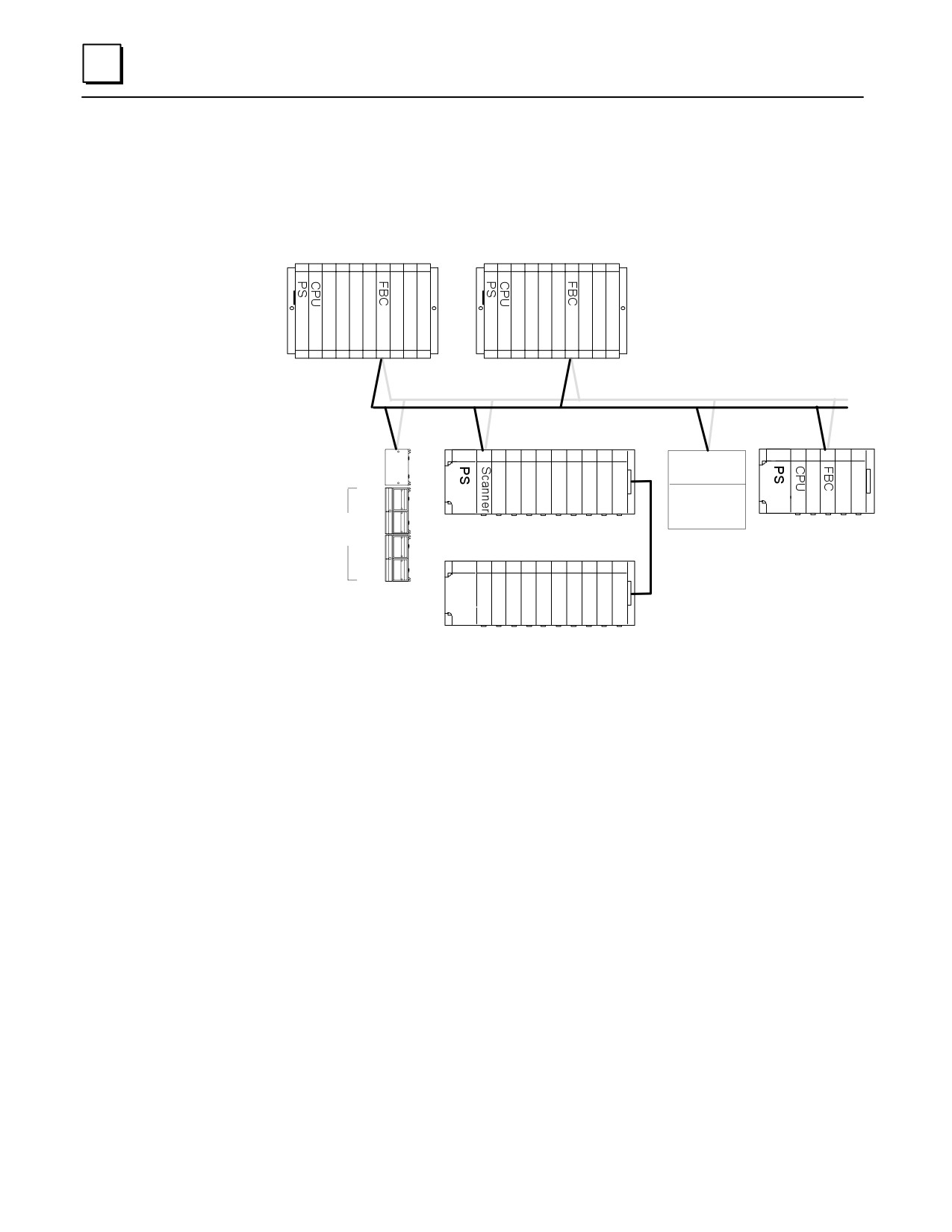
IC693BEM340 FIP Bus Controller (FBC) Module
The Series 90-30 PLC FIP (Factory Instrumentation Protocol) Bus Controller (catalog
number IC693BEM340) is used to interface a FIP I/O serial bus to a Series 90-30 PLC.
Series 90-70 PLC
Series 90-70 PLC
a46559
Optional Redundant FIP I/O Bus
FIP I/O Bus
Field Control
I/O Station
FIP Bus
FIP Inter-
face Module
Interface Unit
Î
ÎÎ
Î
Î
Generic
Î
ÎÎ
Î
Î
Device
Up to 8 Field Control
Î
emote I/O Rack
Series 90-30 PLCÎ
modules (4 shown).
Remote I/O Nest
Î
ÎÎ
ÎÎ
ÎÎÎÎÎÎ
ÎÎ
Optional Expansion Rack
Figure 8-6. Example of FIP I/O System Configuration
A FIP bus is used primarily for I/O control. It also is used to store configuration data to
remote devices and to report faults. Devices that can be on a FIP bus in a Series 90-30 PLC
system include:
Series 90-70 PLC, interfaced to a FIP bus by a Fip Bus Controller.
Field Control Stations, Field Control I/O modules that are interfaced to the bus via a
FIP Bus Interface Unit (BIU).
Remote Drops, Series 90-30 I/O racks that are interfaced to the bus via FIP Remote
I/O Scanner Modules. Each remote drop can include one 5- or 10-slot main rack, one
5- or 10-slot expansion rack and any mix of discrete and analog I/O modules.
Generic Devices, such as general-purpose computers that are interfaced to the bus
via a FIP Interface Module.
8-10
Series 90-30 PLC Installation and Hardware Manual - October 1999
GFK-0356P
8
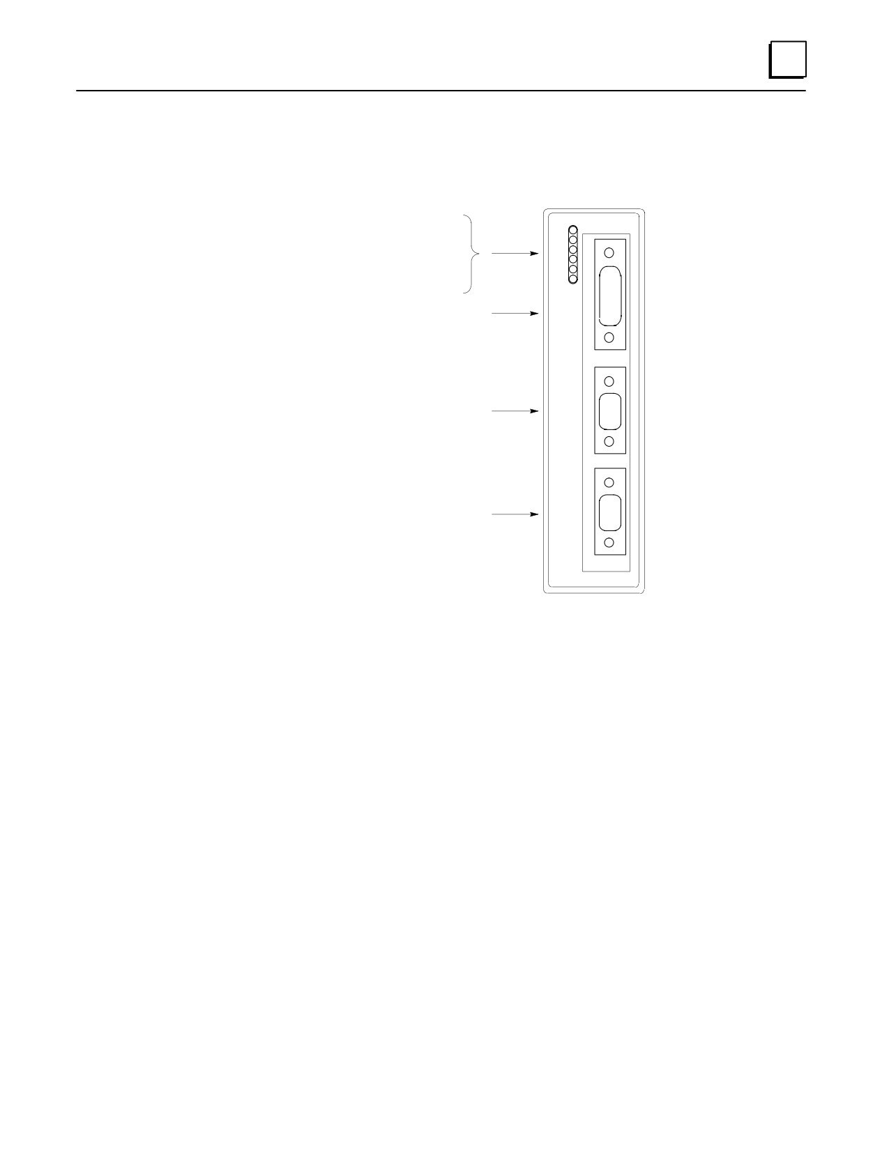
The FIP Bus Controller is a standard, rack-mounted Series 90-30 PLC module. It plugs
easily into the PLC’s backplane. The latch on the bottom of the module secures it in
position.
a46560
Module OK
Run
Carrier Detect Ch. 1
Transmit Enable Ch. 1
Carrier Detect Ch. 2
Transmit Enable Ch. 2
15-Pin Serial Connector RS-485
9-Pin FIP Fieldbus Connector
(channel 1)
9-Pin FIP Fieldbus Connector
(channel 2)
Figure 8-7. Series 90-30 FIP Bus Controller
There are no DIP switches or jumpers to set on the module.
The Series 90-30 FIP Bus Controller has six status LEDs, an RS-485 serial port, and two
identical FIP bus connectors.
Status LEDs
The 6 LEDs on the front of the FIP Bus Controller display module status and
communications activity.
Serial Port
The 15-pin serial port is used to connect a computer for upgrading the operating
firmware of the Bus Controller and for configuring by an external configuration tool.
FIP Bus Connectors
The two 9-pin connectors on the FIP Bus Controller provide for attachment of one or
two FIP busses. The two busses provide a redundant bus capability.
GFK-0356P
Chapter 8 Option Modules
8-11
8
IC693BEM330 FIP Remote I/O Scanner Module
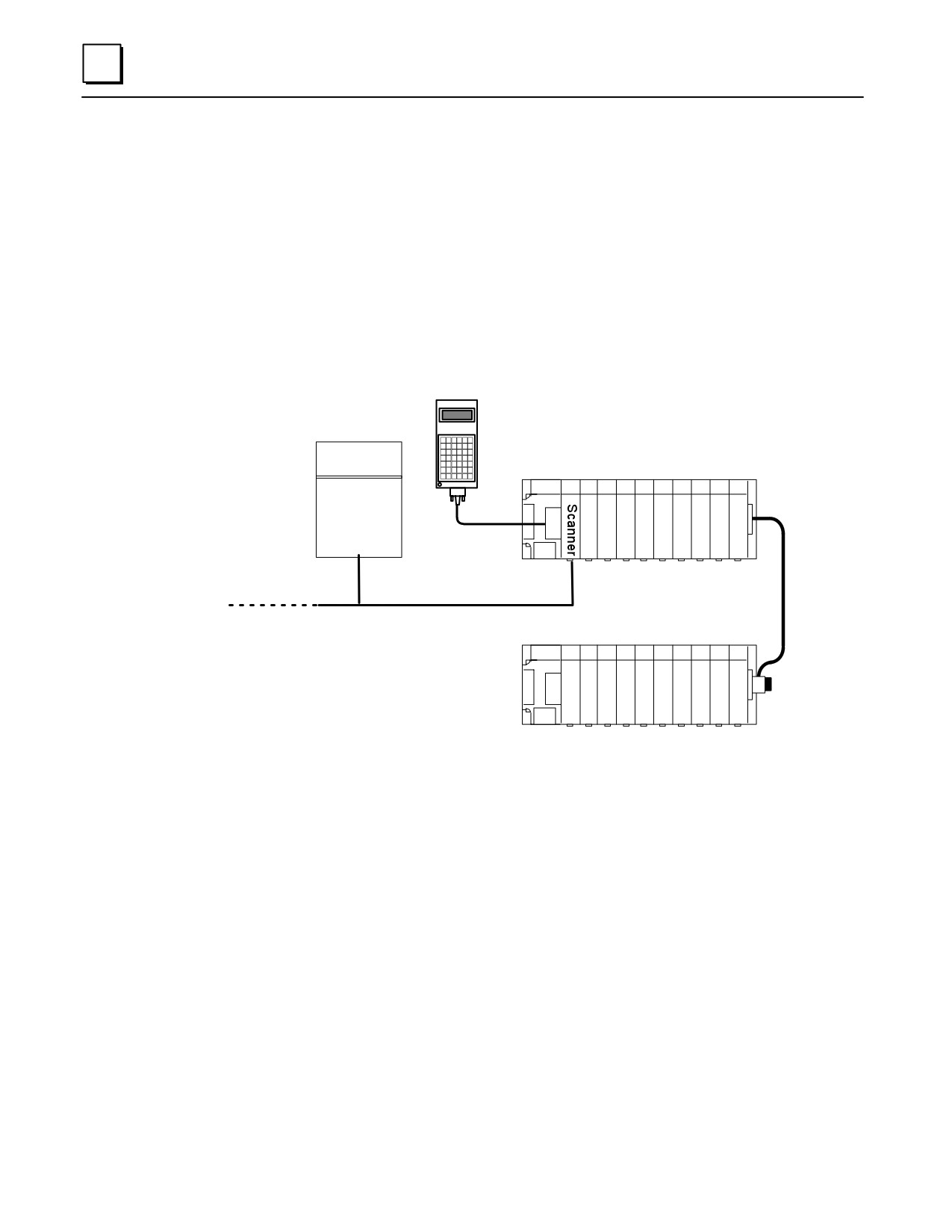
The FIP (Factory Instrumentation Protocol) Remote I/O Scanner (catalog number
IC693BEM330) is an intelligent module that interfaces Series 90-30 I/O modules to a FIP
bus. Up to 19 I/O modules can be accommodated by using two 10-slot baseplates
connected by an expansion cable. Together, the Remote I/O Scanner and the modules it
serves are referred to as an I/O Nest. The FIP Nest can include most Series 90-30 I/O
modules.
The host CPU can be any type of CPU capable of communicating on a FIP bus. A module
in the host (such as a FIP Bus Controller) provides the necessary interface between the
FIP bus and the host CPU.
Hand-held
46550
Programmer
Host CPU
I/O Nest
CPU
FIP
ÎÎÎ
ÎÎ
Bus
Controller
ÎÎ
ÎÎ
ÎÎÎ
ÎÎ
ÎÎÎÎÎÎÎÎÎ
FIP Bus
Expansion Cable,
up to 50 feet (15 Meters)
Up to 128 devices
ÎÎÎ
ÎÎ
ÎÎ
ÎÎ
ÎÎÎÎÎÎÎÎÎÎ
Figure 8-8. Example of FIP Remote I/O Scanner System Configuration
The Series 90-30 Hand-Held Programmer provides a convenient way to perform setup,
monitoring, and control functions.
Features of the Remote I/O Scanner
The FIP Remote I/O Scanner performs the following basic functions:
controls operation of the I/O nest in the selected mode
scans discrete and analog I/O modules and maintains I/O scan timing
maps I/O data to FIP application variables
detects module and system faults and reports them to the FIP network
permits standalone configuration using Hand-Held Programmer
retains its network configuration through loss of power
permits I/O forcing from the Hand-Held Programmer
detects and records input transitions
8-12
Series 90-30 PLC Installation and Hardware Manual - October 1999
GFK-0356P
8
supports FIP messaging services
responds to an external synchronization signal
can provide blinking or pulsed outputs
can provide input filtering and chatter detection
FIP Bus Interface
The Remote I/O Scanner communicates at a data rate of 1MHz. There are two versions
of the FIP communications standard: FIP and WORLD FIP. A DIP switch on the module
is used to select the version that will be used by the Remote I/O Scanner. (The same
communications method will then be used on both bus cables).
The DIP switch on the module must be set to the FIP position for the Remote I/O
Scanner to communicate with a Series 90-70 PLC.
Module Description
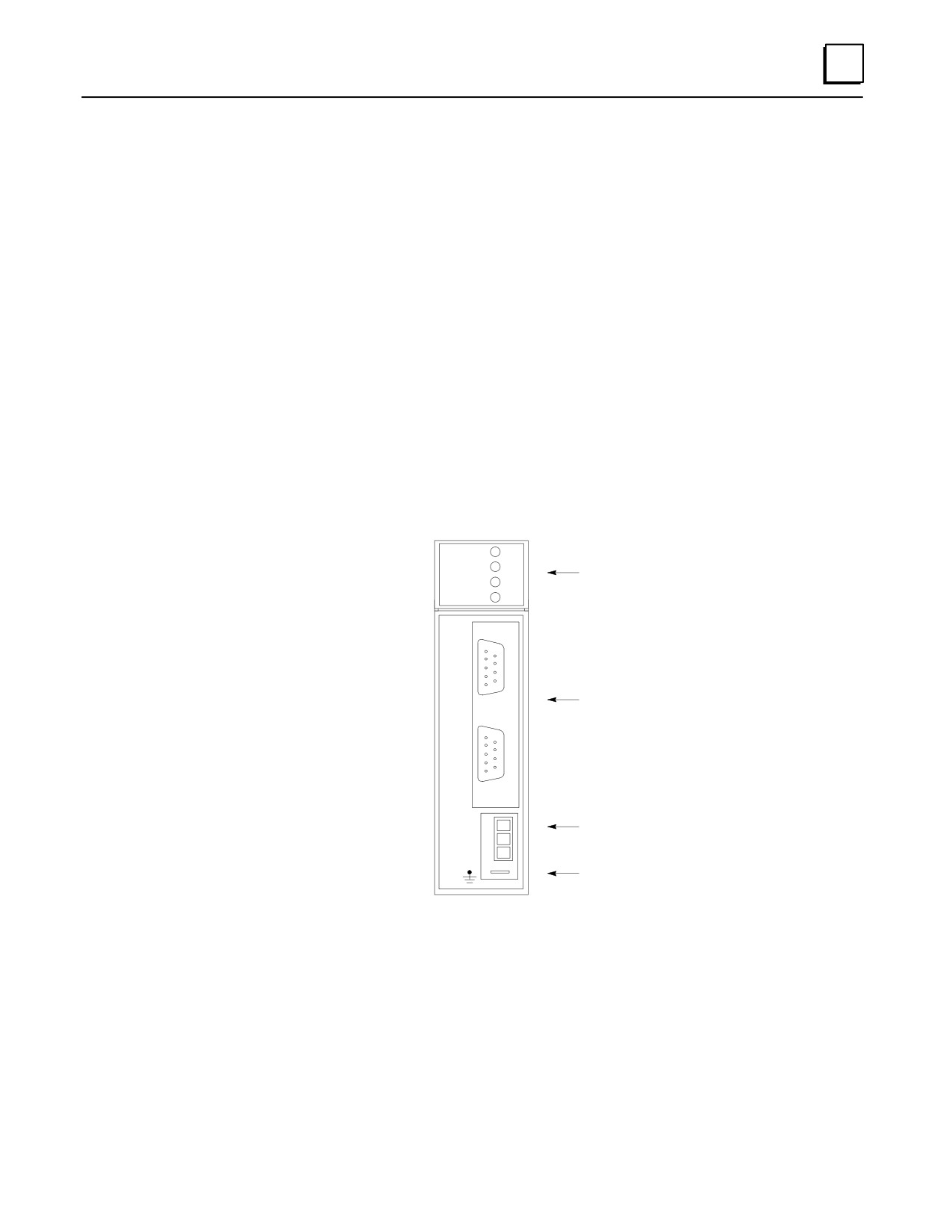
The FIP Remote I/O Scanner is a standard Series 90-30 PLC module that plugs easily
into the backplane of the baseplate.
46551
ÎFIP CH S2ÎCD1Î
1.0 MHz
N1
ÎÎÎÎTE
LEDs
CD2
N2
ÎÎÎÎTE
ÎÎÎÎÎ
C
ÎÎAÎÎÎ
ÎÎNÎÎÎ
E
1
ÎÎLÎÎÎ
FIP Bus Connectors
ÎÎCÎÎÎ
ÎÎAÎÎÎ
N
ÎÎEÎÎÎ
L
ÎÎ2ÎÎÎ
ÎÎSÎÎÎ
Synchro Connector
ÎÎNÎÎÎ
C
ÎÎRÎÎÎ
O
Lug for Ground Wire
ÎÎÎÎÎ
ÎÎÎÎÎ
Figure 8-9. FIP Bus Interface Module
Connectors
The front of the module has the following connectors:
CHANNEL 1
9-pin male D connectors for two FIP bus cables. A bus can be
CHANNEL 2
disconnected from the module without disturbing the continuity of the
bus. The second bus is a backup for the first bus; its use is optional.
GFK-0356P
Chapter 8 Option Modules
8-13