FANUC Series 90-30 PLC. Installation and Hardware Manual (GFK-0356P) - page 9
10
IC690CBL701
PCM, ADC, CMM to Workmaster (PC-XT) Cable
NOTE: This cable was designed for use with older computers such as
PC or XT types and would not likely be used for new projects.
Function of cable
This cable provides RS-232 signal connections between the RS-232 port on a PCM, ADC,
or CMM module and a serial port on a Workmaster computer or IBM-XT or equivalent
Personal Computer.
Cable Specifications
Cable Length
10 feet (3 meters)
Connectors
PCM/ADC/CMM
25-pin male, D-subminiature type, AMP 205208-1, or equivalent
Side
9-pin male, D-subminiature type, AMP 205203-1, or equivalent
Programmer Side
Cable Clamps
25-pin
AMP 207908-7 or equivalent
9-pin
AMP 207908-1 or equivalent
Cable Type
Six conductor, overall shield, non-paired AWG #24 (.21 mm2),
Belden 9536 or equivalent
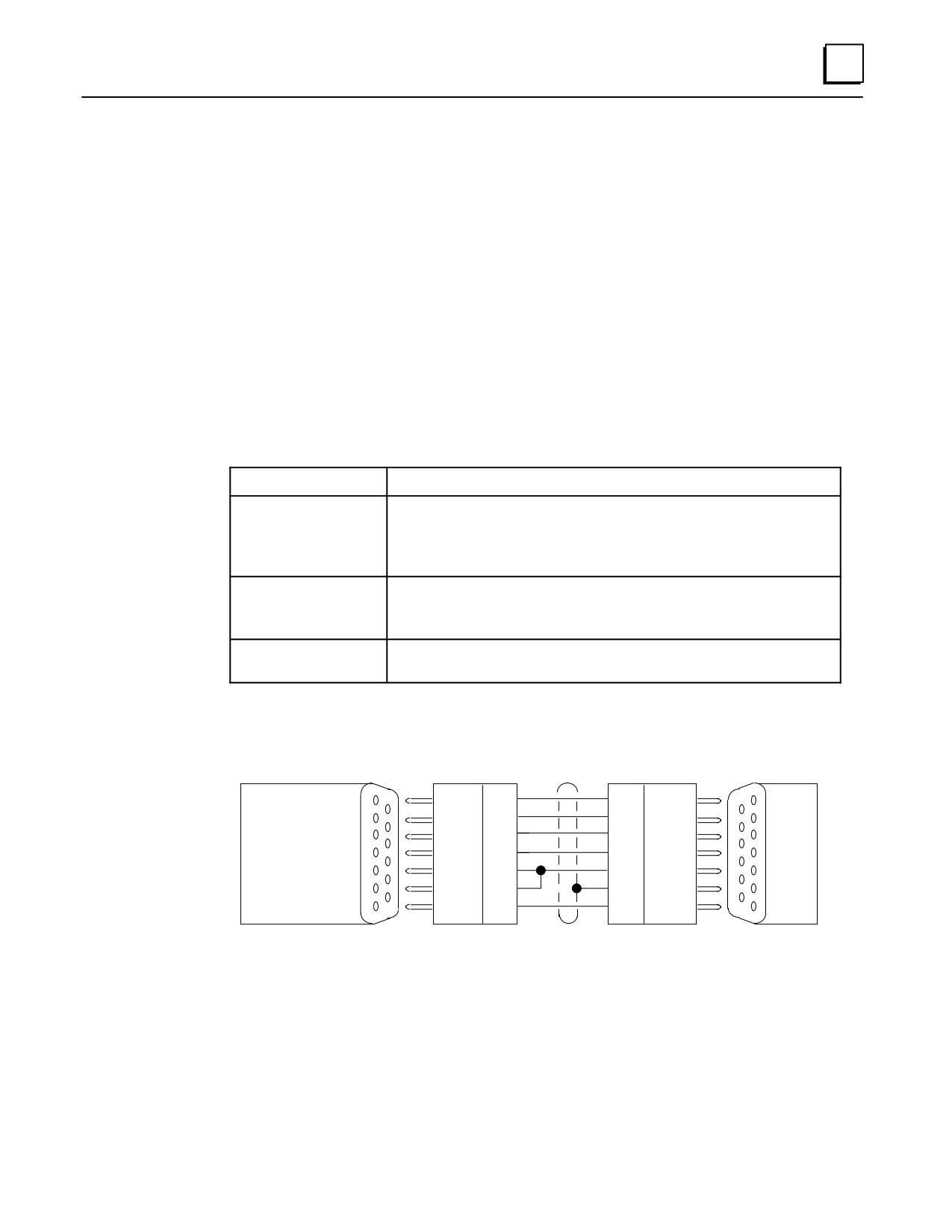
Wiring Diagram
PIN
PIN
a42831
Î
ÎÎ
TD
2
3
RD
ÎÎ
RD
3
2
TD
ÎÎ
RTS
4
5
CTS
WORKMASTER
ÎÎ
ÎÎPCM
CTS
5
20
DTR
OR
ÎÎ
DCD
8
8
DCD
ÎÎ
IBM PC-XT
DTR
9
1
SHLD
ÎÎ
ÎÎ
GND
7
7
GND
ÎÎ
ÎÎ
9- PIN
9- PIN
25- PIN
25- PIN
FEMALE
MALE
MALE
FEMALE
Figure 10-5. PCM, ADC, or CMM to Workmaster or PC-XT Serial Cable
Note
Although the IC690CBL701 and 702 cables look identical (except for
catalog number labeling), the internal pin connections are different.
GFK-0356P
Chapter 10 Cables
10-13
10
PCM to Programmer Cable Installation
Caution
The Series 90-30 PLC baseplate that contains the PCM, ADC, or CMM
and the programmer ground connections must be at the same ground
potential. Incorrect wiring will result in damage to the programmer or
the module.
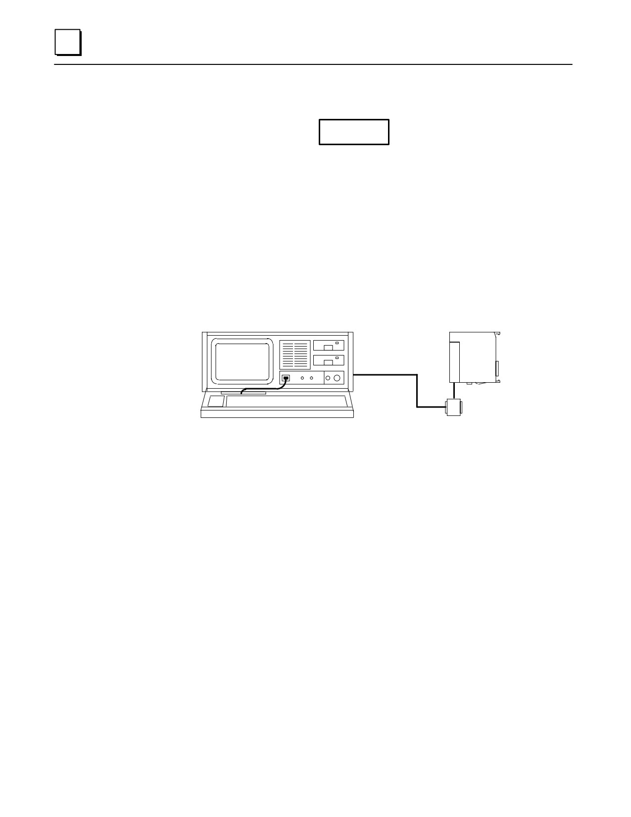
Select the WYE cable (IC693CBL305 or IC693CBL304).
Connect the IC690CBL701 cable’s 9-pin female connector to the male RS-232
connector (serial port) on the selected programming device.
Connect the cable’s 25-pin male connector to the Port 1 connector on the WYE cable.
Connect the 25-pin male connector on the WYE cable to the female connector on
the front of the PCM, ADC, or CMM module.
WORKMASTER
a44748
ÎÎÎÎ
IC690CBL701
RS-232
PCM
ÎÎÎÎ
(DEFAULT PORT)
ÎÎÎÎÎ
IC693CBL305B
ÎÎÎÎÎÎÎÎÎÎÎ PORT 1
Figure 10-6. PCM to Workmaster Computer or PC-XT Personal Computer
10-14
Series 90-30 PLC Installation and Hardware Manual - October 1999
GFK-0356P
10
IC690CBL702
PC-AT to PCM, ADC, CMM Cable
Function of cable
This cable provides RS-232 signal connections between the RS-232 port on a PCM, ADC,
or CMM module and a serial port on an IBM PC-AT or equivalent Personal Computer.
Cable Specifications
Cable Length
10 feet (3 meters)
Connectors
PCM/ADC/CMMSide
25-pin male, D-subminiature type, AMP 205208-1, or equivalent
Programmer Side
9-pin male, D-subminiature type, AMP 205203-1, or equivalent
Cable Clamps
25-pin
AMP 207908-7 or equivalent
9-pin
AMP 207908-1 or equivalent
Cable Type
Six conductor, overall shield, non-paired AWG #24 (.21 mm2), Belden 9536 or equivalent
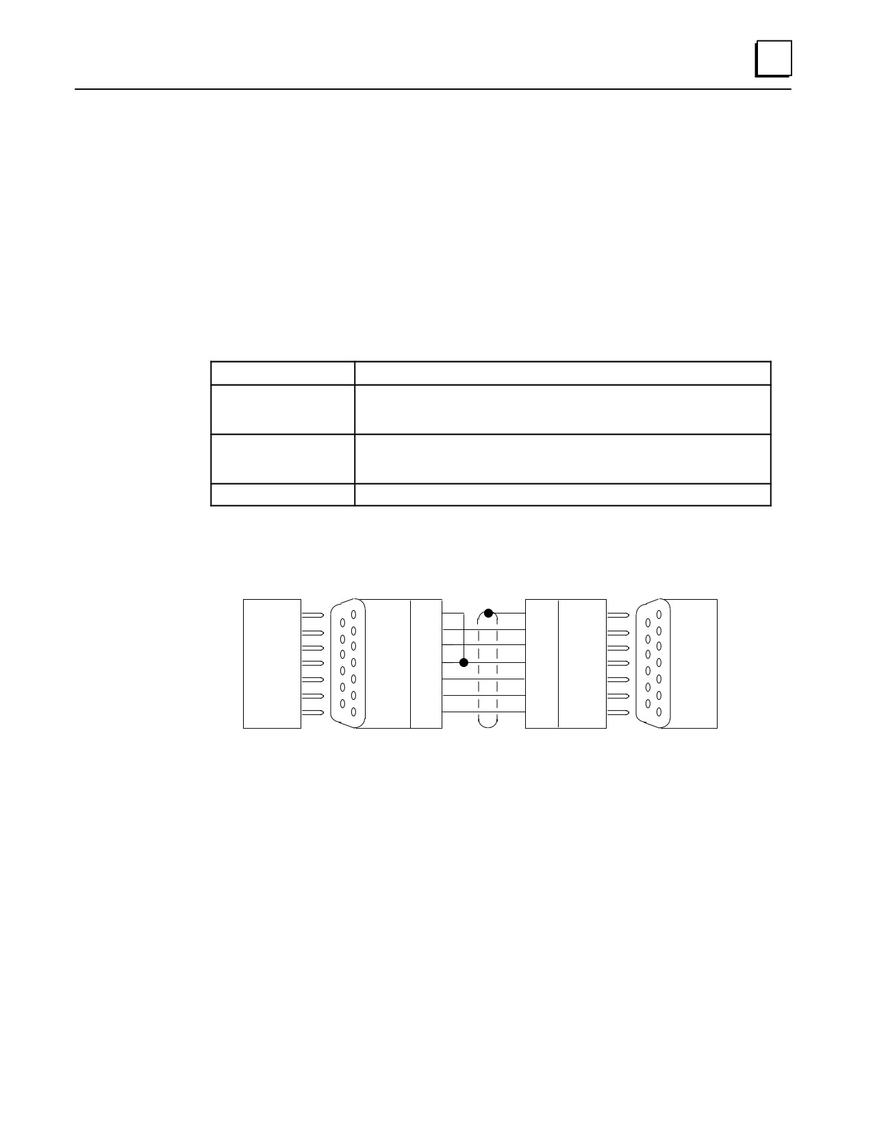
Wiring Diagram
PIN
PIN
a42832
DCD
1
1
SHLD
Î
Î
RD
2
2
TD
Î
Î
TD
3
3
RD
PC-AT
Î
DTR
4
8
DCD
Î
PCM
RTS
7
5
CTS
Î
Î
CTS
8
20
DTR
Î
GND
5
7
GND
Î
Î
Î
9- PIN
9- PIN
25- PIN
25- PIN
MALE
FEMALE
MALE
FEMALE
Figure 10-7. PCM, ADC, or CMM to Workmaster or PC-AT Serial Cable
Note
Although the IC690CBL701 and 702 cables physically look identical
(except for catalog number labeling), the internal pin connections are
different.
GFK-0356P
Chapter 10 Cables
10-15
10
PCM to Programmer Cable Installation
Caution
The Series 90-30 PLC baseplate that contains the PCM, ADC, or CMM
and the programmer ground connections must be at the same ground
potential. Incorrect wiring will result in damage to the programmer or
the module.
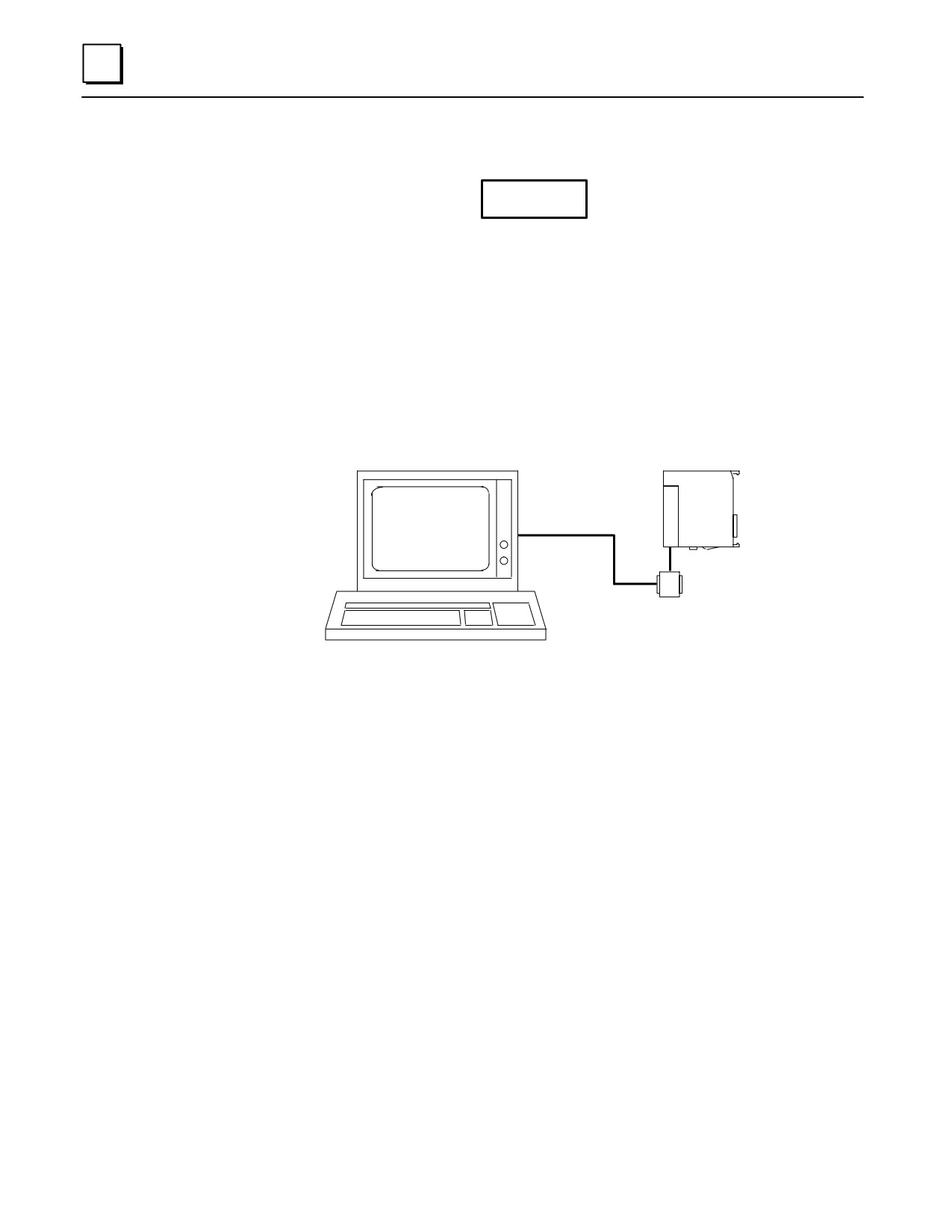
Select the WYE cable (IC693CBL305 or IC693CBL304).
Connect the IC690CBL702 cable’s 9-pin female connector to the male RS-232
connector (serial port) on the selected programming device.
Connect the cable’s 25-pin male connector to the Port 1 connector on the WYE cable.
Connect the 25-pin male connector on the WYE cable to the female connector on
the front of the PCM, ADC, or CMM module.
PC-AT
a44749
IC690CBL702
RS-232
PCM
(DEFAULT PORT)
IC693CBL305B
PORT 1
ÎÎÎÎÎÎÎÎÎÎ
ÎÎÎÎÎÎÎÎÎÎ
ÎÎÎÎÎÎÎÎÎÎ
Figure 10-8. PCM to PC-AT Personal Computer
10-16
Series 90-30 PLC Installation and Hardware Manual - October 1999
GFK-0356P
10
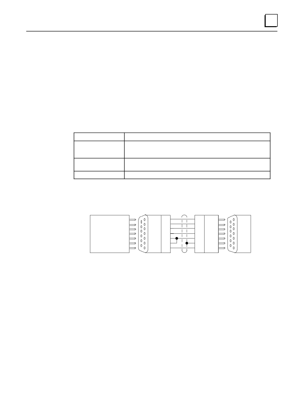
IC690CBL705
Workmaster II (PS/2) to PCM, ADC, CMM Cable
Function of cable
This cable provides RTS-232 signal connections between the RS-232 port on a PCM,
ADC, or CMM module and a serial port on a Workmaster II or an IBM Personal System 2
(PS/2) or equivalent Personal Computer.
Cable Specifications
Cable Length
10 feet (3 meters)
Connectors
PCM/ADC/CMMSide
25-pin male, D-subminiature type, AMP 205208-1, or equivalent
Programmer Side
25-pin female, D-subminiature type, AMP 205207-1, or equivalent
Cable Clamps
25-pin
AMP 207908-7 or equivalent
Cable Type
Six conductor, overall shield, non-paired AWG #24 (.21 mm2), Belden 9536 or equivalent
Wiring Diagram
PIN
PIN
a44033
TD
2
3
RD
Î
RD
3
2
TD
ÎÎ
WORKMASTER II
4
5
CTS
AND
ÎRTS
ÎÎ
PCM
CTS
5
20
DTR
IBM PS/2
DCD
8
8
DCD
Î
ÎÎ
DTR
20
1
SHLD
Î
ÎÎ
GND
7
7
GND
25- PIN
25- PIN
25- PIN
25- PIN
MALE
FEMALE
MALE
FEMALE
Figure 10-9. PCM, ADC, or CMM to Workmaster II or PS/2 Serial Cable
GFK-0356P
Chapter 10 Cables
10-17
10
PCM to Programmer Cable Installation
Caution
The Series 90-30 PLC baseplate that contains the PCM, ADC, or CMM
and the programmer ground connections must be at the same ground
potential. Incorrect wiring will result in damage to the programmer or
the module.
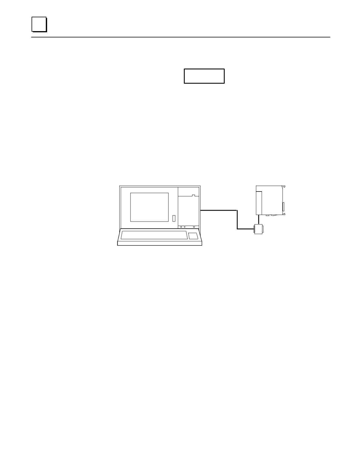
Select the WYE cable (IC693CBL305 or IC693CBL304).
Connect the IC690CBL705 cable’s 25-pin female connector to the male RS-232
connector (serial port) on the selected programming device.
Connect the cable’s 25-pin male connector to the Port 1 connector on the WYE cable.
Connect the 25-pin male connector on the WYE cable to the female connector on
the front of the PCM, ADC, or CMM module.
WORKMASTER II
a44747
ÎÎÎÎÎ
IC690CBL705
RS-232
PCM
ÎÎÎÎÎ
(DEFAULT PORT)
ÎÎÎÎÎ
ÎÎÎÎÎ
IC693CBL305B
ÎÎÎÎÎÎÎ
ÎÎ
Î
PORT 1
ÎÎÎÎÎÎÎÎÎÎ
ÎÎÎÎÎÎÎÎÎÎ
Figure 10-10. PCM to Workmaster II Computer or PS/2 Computer
10-18
Series 90-30 PLC Installation and Hardware Manual - October 1999
GFK-0356P
10
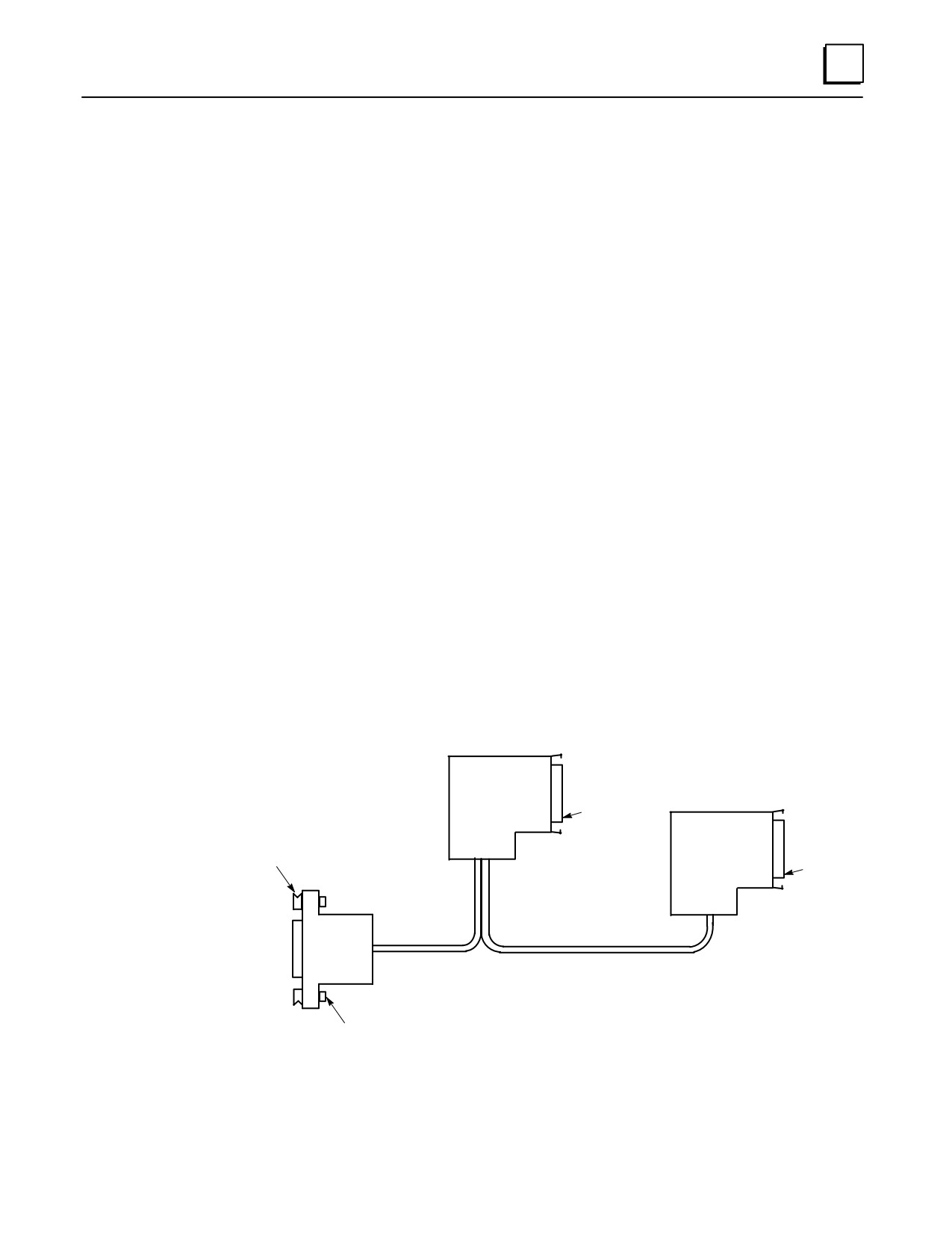
IC690CBL714A Multidrop Cable
Purpose
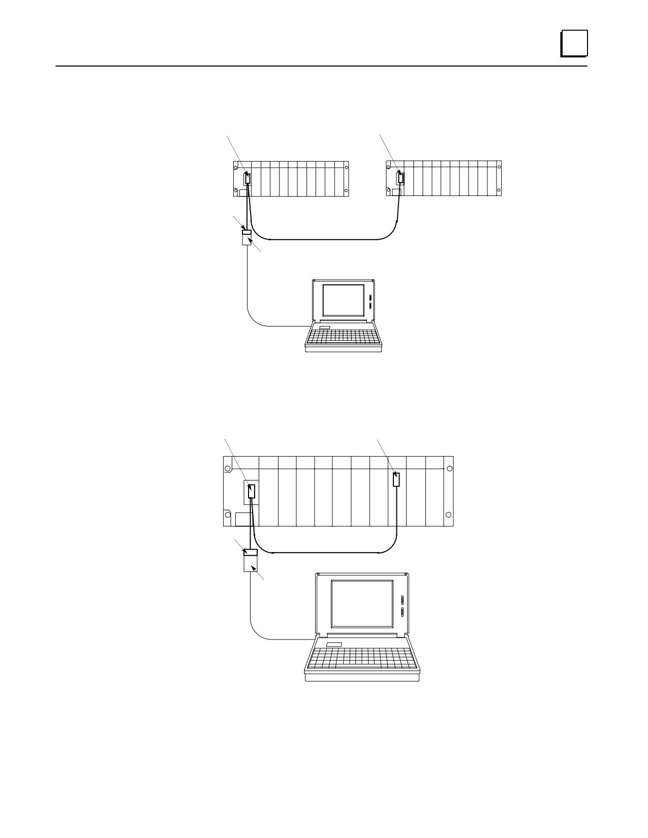
This cable has a number of possible applications with Series 90 products:
To interconnect Series 90-30 PLCs or redundant Series 90-30 PLCs in a multidrop
configuration.
To interconnect a Series 90-30 PLC and APM module in a multidrop configuration
with a single personal computer (programmer). This allows programming and
troubleshooting both PLC and APM without moving connection cables.
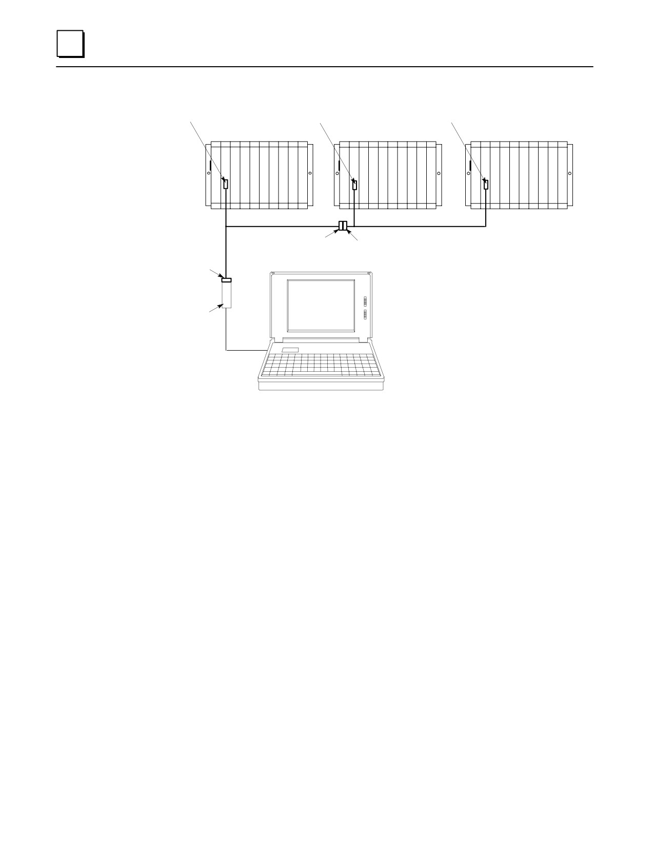
To interconnect Series 90-70 or redundant Series 90-70 PLCs in a multidrop
configuration.
Specifications
Connector A: DB15F, 15-pin female connector with M3 latchblocks
Connectors B and C: DB15M, 15-pin right angle, male connector with spring clips
Wire: Cable consists of three individually shielded pairs of 22-gauge stranded
conductors. Belden #8777 or equivalent.
Jumpers: All jumpers are made of #22 AWG (UL1061) type individual wires.
Length: The length from the back of Connector A to entry into Connector B is 6
inches (+/- 0.5 inch). The length from the back of Connector C to entry into
Connector B is 40 inches (+/- 1.0 inch).
Connector B
Connector C
Connector A
Pin 1
M3 Latching
Blocks (2)
Pin 1
M3 pan head screws (2).
Screws must not protrude
through the end of the Latching
Blocks.
GFK-0356P
Chapter 10 Cables
10-19
10
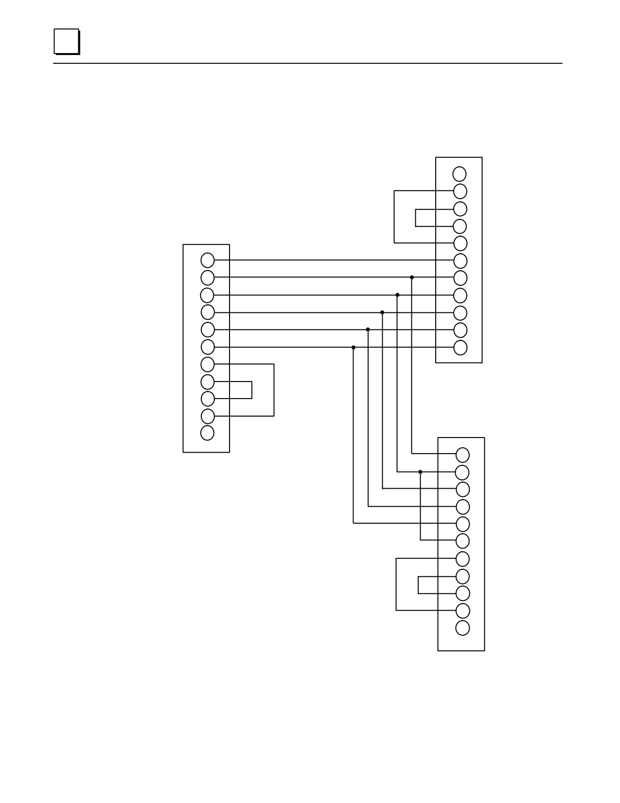
IC690CBL714A Multi-Drop Cable Wiring Diagram
Connector A, 15-pin Female,
to other CPU or Adapter
N.C.
9
6
8
Connector B, 15-pin male,
to CPU SNP Port
14
15
5
5
7
7
10
10
11
11
12
12
13
13
6
8
14
15
9
N.C.
7
10
11
12
NOTE: Trim all drain wires
13
flush with the jacket.
9
6
8
14
15
N.C.
5
Connector C, 15-pin male, to
next CPU or final term.
Figure 10-11. Connecting Diagram for Multidrop Cable IC690CBL714A
10-20
Series 90-30 PLC Installation and Hardware Manual - October 1999
GFK-0356P
10
Connection Diagrams for IC690CBL714A Cable
Conn. B
Conn. C
Series 90-30 PLC
Series 90-30 PLC
Conn. A
IC690CBL714A Cable
IC690ACC901
Miniconverter
Serial Cable
Figure 10-12. Multidrop Arrangement for Series 90-30 Redundant System
Conn. B
Conn. C to APM Comm. Port
Series 90-30 PLC
PS
CPU
APM
Conn. A
IC690CBL714A Cable
IC690ACC901
Miniconverter
Serial Cable
Figure 10-13. Connecting CPU and APM to Programmer with IC690CBL714A Cable
GFK-0356P
Chapter 10 Cables
10-21
10
a47100
Conn. B
Conn. B
Conn. C
PLC A
PLC
B
PLC C
C
C
C
P
P
P
U
U
U
IC690CBL714A
IC690CBL714A
Conn. C
Conn. A
Conn. A
RS-232/422
Converter
Figure 10-14. Multidrop Arrangement for Series 90-70 TMR Redundant System
10-22
Series 90-30 PLC Installation and Hardware Manual - October 1999
GFK-0356P
10
IC693CBL300/301/302/312/313/314
I/O Bus Expansion Cables
(Includes Instructions for Building Custom Length Cables)
Description
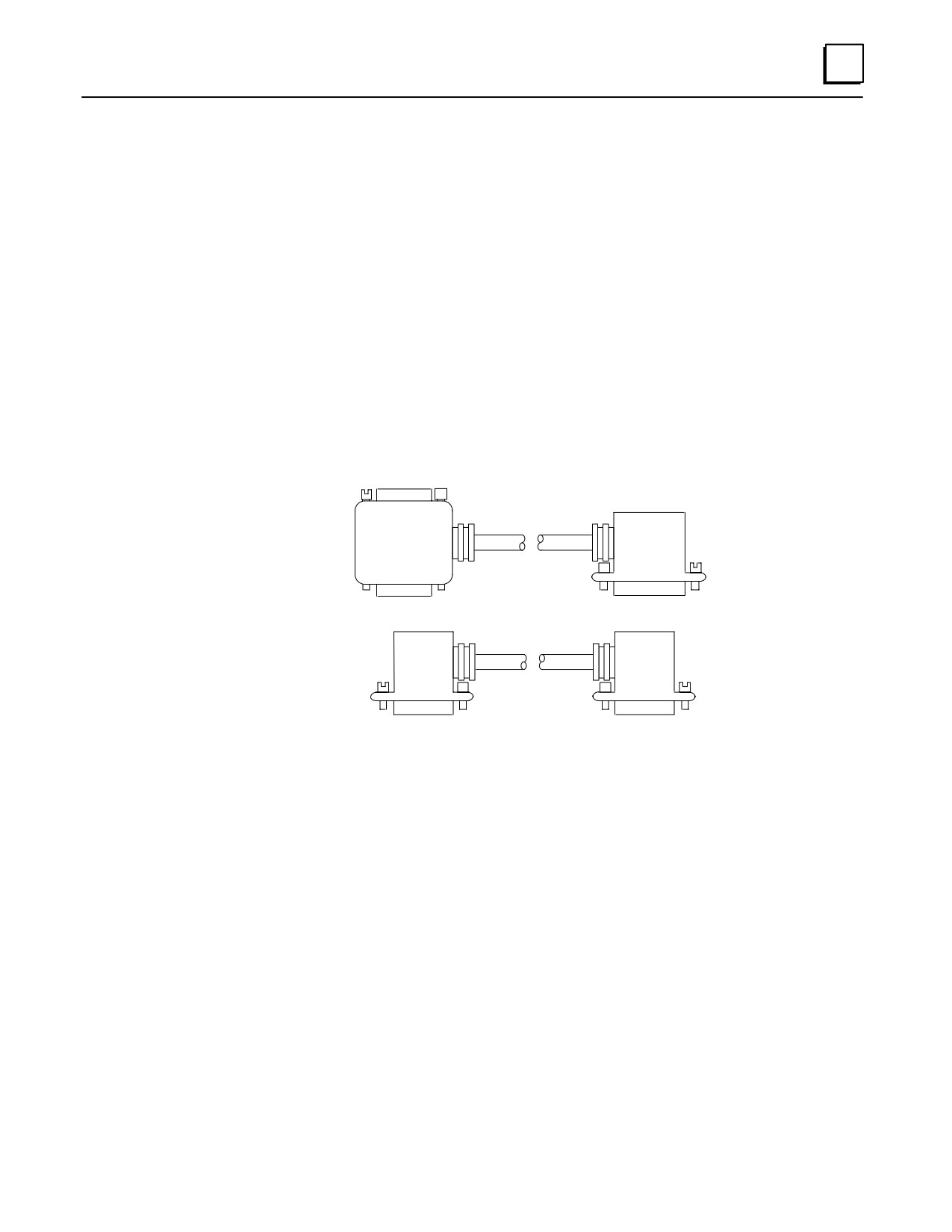
I/O bus expansion cables (IC693CBL300, 301, 312, 313, 314), called “Wye cables,” have a
single male 25-pin D connector on one end and a two-headed (one male, one female)
25-pin D connector on the other end as shown in (A) of the figure. The 50 foot (15m)
(IC693CBL302) cable has a single male connector on the CPU baseplate end and a single
terminated male connector on the expansion baseplate end. The 3 foot cable
(IC693CBL300) can also be used as a WYE adapter cable to simplify building custom length
cables (see the section “Cable Application Suggestions” later in this Chapter).
FEMALE
a43853
CONNECTOR
ÎÎ Î
Î
ÎÎ
ÎÎ
A
ÎÎ
ÎÎ
ÎÎ
.5, 3, 6, 26 FOOT
Î
ÎÎ
CABLES
ÎÎ
ÎÎ Î
MALE
MALE
CONNECTOR
CONNECTOR
ÎÎ
Î ÎÎ
B
ÎÎ
ÎÎ
ÎÎ
50 FOOT
CABLE
ÎÎ
ÎÎ
MALE
MALE
CONNECTOR
CONNECTOR
Figure 10-15. Detail of I/O Bus Expansion Cables
Cable Lengths
IC693CBL300
3 feet (1 meter), continuous shield
IC693CBL301
6 feet (2 meters), continuous shield
IC693CBL302 or IC693CBL314
50 feet (15 meters), continuous shield
IC693CBL312
0.5 feet (0.15 meters), continuous shield
IC693CBL313
25 feet (8 meters), continuous shield
Function of Cables
The I/O Bus expansion cables are used to extend the I/O bus to expansion or remote
baseplates in a Series 90-30 I/O system when additional I/O slots are needed or
baseplates are required some distance from the CPU baseplate. The prewired I/O bus
expansion cables can be used for connecting either expansion or remote baseplates.
Where required cable length is not available in a standard cable, a custom cable must be
built (see the section “Building Custom Length I/O Bus Expansion Cables” for detailed
instructions).
GFK-0356P
Chapter 10 Cables
10-23
10
Connecting the Cables
Connect the single male connector to the 25-pin female connector on the right side
of the CPU baseplate.
Connect the male connector on the dual connector end of the cable to the 25-pin
female connector on the first expansion baseplate.
Connect the unused 25-pin female connector on the dual connector end of the cable
to either the single male connector of a second I/O bus expansion cable to continue
the I/O bus expansion chain, or to an I/O bus Terminator plug if this is the last cable
in the expansion chain.
Important Notes About I/O Bus Expansion Cables
1.
The maximum number of cables that can be included in an I/O expansion system is
seven, and the total maximum cable length between the CPU baseplate and the last
expansion baseplate is 50 feet (15 meters). The total maximum cable length between
the CPU baseplate and the last remote baseplate is 700 feet (213 meters). Failure to
observe these maximum cable lengths could result in erratic operation of the PLC
system.
2.
CPUs 350 - 364 support a maximum of seven I/O expansion cables. CPUs 331 - 341
support a maximum of four I/O expansion cables.
3.
The 50 foot (15 meter) I/O bus expansion cable (IC693CBL302), which has a male
connector on each end, has the I/O bus terminating resistors built into the end
connector on the cable. If this cable is used, you would not install a separate terminator
block.
Caution
I/O Bus Expansion cables should NOT be connected or disconnected
with power applied to the I/O expansion baseplate(s). Unexpected
PLC operation may result.
Cable Application Suggestions
In general, it is advantageous to use standard, factory-built cables, where possible, to
save time and avoid wiring errors.
Using Standard Cables
For connecting between baseplates (either between a CPU and expansion baseplate,
between two expansion baseplates or between two remote baseplates) in the same
cabinet when a standard length (0.5, 1, 2, 8, or 15 meters) will fit the need.
As a Wye jumper for custom built point-to-point cables (IC693CBL300 is often used
for this). This combination saves time since a point-to-point cable can be built much
faster than a Wye cable. An example of this is shown in Figure 10-23.
Using Custom Built cables
When you need a cable length not available in a standard size.
When a cable must be routed through a conduit that is not large enough for a
standard cable’s connector to fit through.
10-24
Series 90-30 PLC Installation and Hardware Manual - October 1999
GFK-0356P
10
Building Custom Length I/O Bus Expansion Cables
This section provides details needed to create custom length I/O Bus Expansion cables.
Two Types of Custom Built Cables
The two types are:
Point-to-Point - these have a single male connector on one end and a single female
connector on the other end. These are usually used with the IC693CBL300 which
supplies the Wye connection. This combination saves time since a point-to-point
cable can be built much faster than a Wye cable.
Wye - these have a single male connector on one end and two connectors (one male
and one female) on the other end.
Components Needed to Build Custom Length I/O Bus Expansion Cables
Note: the special two-headed Wye connector used on the standard Wye cables is not
available as a separate component.
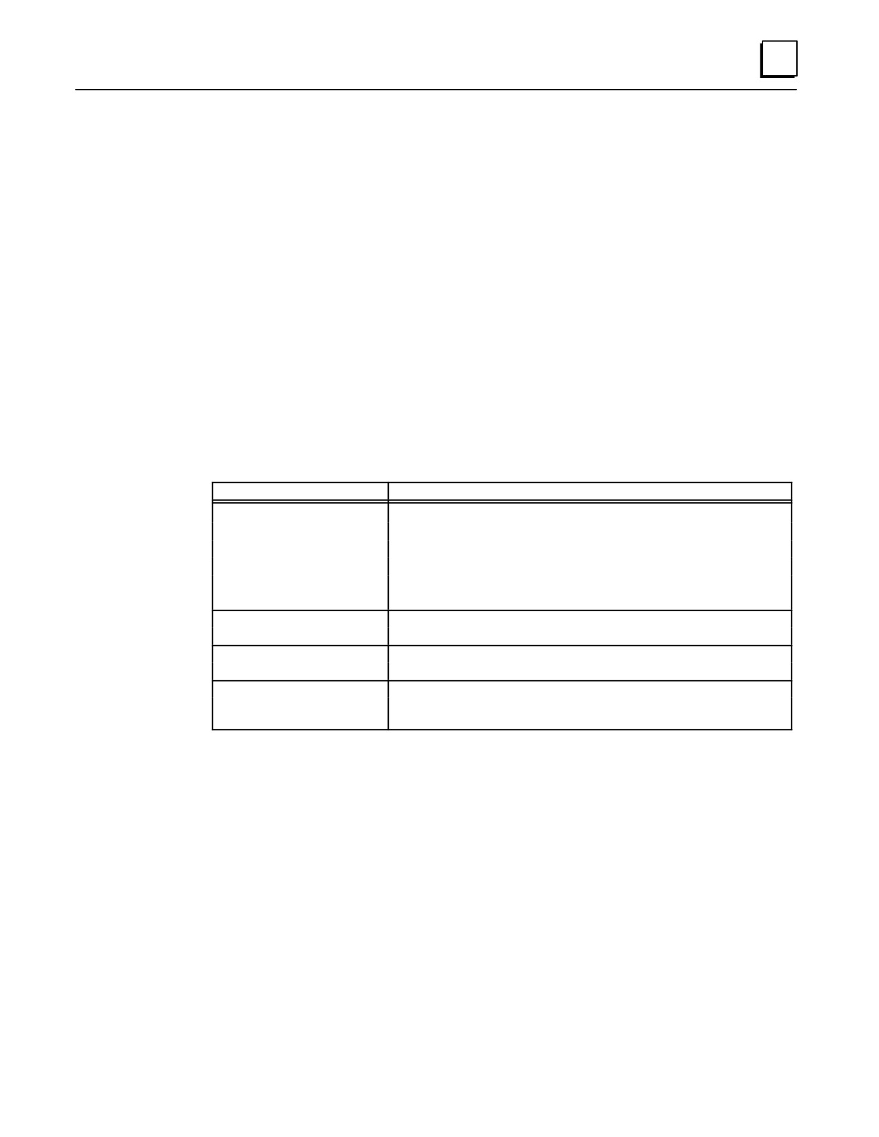
Item
Description
Cable:
Belden 8107 only (no substitutes):
Computer cable, overall braid over foil shield, twisted-pair
30volt/80 C (176 F)
24 AWG (.22 mm2) tinned copper, 7 x 32 stranding
Velocity of propagation = 70%
Nominal impedance = 100Ω
25 PinMale Connector:
Crimp Plug = Amp 207464-1; Pin = Amp 66506-9
Solder Plug = Amp 747912-2
25 Pin FemaleConnector:
Crimp Receptacle = Amp 207463-2; Pin = Amp 66504-9
Solder Receptacle = Amp 747913-2
ConnectorShell:
Kit - Amp 745833-5:
Metal-plated plastic (plastic with nickel over copper)
Crimp ring - Amp 745508-1, split ring ferrule
= Critical Information
Vendor part numbers listed for user assembled cables are provided for reference only and do not
suggest or imply that they are preferred. Any part meeting the same specification can be used.
GFK-0356P
Chapter 10 Cables
10-25
10
Expansion Port Pin Assignments
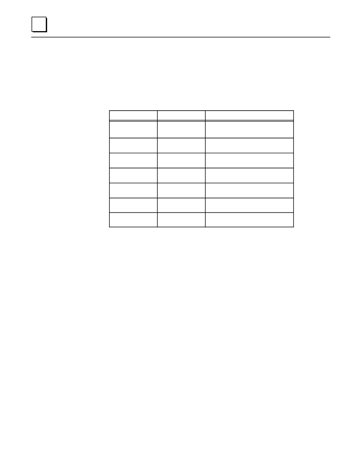
The following table lists the expansion port pin assignments you will need when
building remote cables. All connections between cables are point-to point, that is, pin 2
of one end to pin 2 of the opposite end, pin 3 to pin 3, etc.
Table 10-2. Expansion Port Pin Assignments
Pin Number
Signal Name
Function
16
DIODT
I/O Serial Data Positive
17
DIODT/
I/OSerialDataNegative
24
DIOCLK
I/O Serial Clock Positive
25
DIOCLK/
I/OSerialClockNegative
20
DRSEL
Remote Select Positive
21
DRSEL/
Remote Select Negative
12
DRPERR
Parity Error Positive
13
DRPERR/
Parity ErrorNegative
8
DRMRUN
Remote Run Positive
9
DRMRUN/
Remote Run Negative
2
DFRAME
Cycle Frame Positive
3
DFRAME/
Cycle FrameNegative
1
FGND
Frame Ground for Cable Shield
7
0V
LogicGround
I/O Expansion Bus Termination
When two or more baseplates are cabled together in an expansion system, the I/O
expansion bus must be properly terminated. The I/O bus must be terminated at the last
baseplate in an expansion system. Each signal pair is terminated with 120 ohm, 1/4 watt
resistors wired between the appropriate pins, as follows (see the above table, also):
pins 16 - 17; 24 - 25;
20 - 21;
12 - 13;
8 - 9;
2 - 3
The I/O bus termination can be done one of the following ways:
By installing an I/O Bus Terminator Plug, catalog number IC693ACC307, on the last
expansion baseplate (local expansion baseplate or remote baseplate) in the system.
The Terminator Plug has a resistor pack physically mounted inside of a connector.
The I/O Bus Terminator Plug is shipped with each baseplate; only the last baseplate
in the expansion chain can have the I/O Bus Terminator Plug installed. Unused I/O
Bus Terminator Plugs can be discarded or saved as spares.
If an expansion system has only one expansion baseplate, the I/O bus can be
terminated by installing as the last cable, the 50 foot (15 meter) I/O Expansion cable,
catalog number IC693CBL302 or IC693CBL314. These cables have the termination
resistors installed in the end that connects to the expansion baseplate connector.
You can also build a custom cable with termination resistors wired to the appropriate
pins for installation at the end of the bus.
10-26
Series 90-30 PLC Installation and Hardware Manual - October 1999
GFK-0356P
10
Shield Treatment
All GE Fanuc factory made cables are made with a continuous, or 100% shield. This
means that the braided cable shield is connected to the metal shell of the connector
around the entire perimeter of the connector. This provides a low impedance path to
frame ground for any noise energy that is coupled onto the cable shield.
For custom length cables made per Figure 10-18, the best noise immunity is achieved
when using a metalized connector cover that makes contact with the cable’s braided and
foil shielding and with the connector shell on the terminating end.
Note
It is not sufficient to only solder the drain wire to the connector shell. It
is required that the cable’s shield be continuous across the entire length
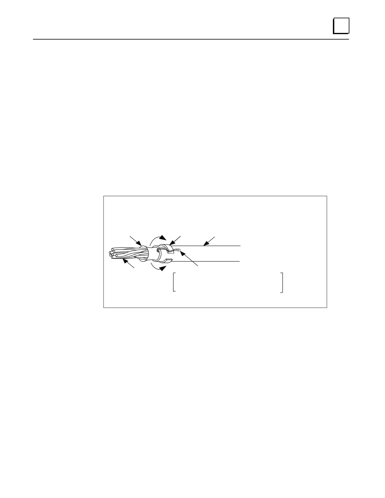
of the cable, including at the terminations. The figure below shows the
recommended method for folding the braided shield back before
inserting the cable into a metallized cover.
a45524
Foil & Braid
(to be folded back
over ferrule and
Split-Ring
Cable
ground wire)
Ferrule
Jacket
Ground Wire
Conductors
Attach to Pin 1 for custom length cables
OR
Fold back for custom Wye cables. *
* See “Alert for Users of Early Remote Baseplate Versions” for
description of when to attach drain wire to pin 1.
Figure 10-16. How to use Split-Ring Ferrules for Foil and Braided Cable Shield
For typical industrial applications, all expansion and remote baseplate cables can be
made with plastic shell covers and should be wired as shown in Figure 10-19. In either
case, pin 1 should be wired into both ends of the custom length cable and the
recommendations listed below should be followed for the Wye cables treatment in the
remote (IC693CHS392/399) baseplates.
When using 100% shielded cables all local (CPU and expansion) baseplates in the system
must be solidly referenced to the same ground point or a potential difference between
baseplates could disturb signal transmission.
Alert for Users of Early Remote Baseplate Versions
In early remote baseplates versions, IC693CHS393E (and earlier) and IC693CHS399D
(and earlier), it is necessary to remove pin 1 of the mating cable where the cable plugs
into the baseplate. This means that when using a factory made Wye cable, such as
IC693CBL300, you must break pin 1 out of the male end where it plugs into the remote
GFK-0356P
Chapter 10 Cables
10-27
10
baseplate before using it with one of these baseplates. Custom built Wye cables for these
baseplates should be built using Figure 10-20.
Remote baseplates IC693CHS393F (and later) and IC693CHS399E (and later) have a
change inside the baseplate which eliminates the need to remove pin 1 from the mating
cable. When using factory made Wye cable with these baseplates, it is not necessary to
remove pin 1 from the cable. Custom built Wye cables for these baseplates can be made
using either Figure 10-20 or Figure 10-21. Figure 10-21 shows how the standard (factory
made) Wye cables are made.
By removing pin 1 in custom built Wye cables made for the earlier versions of remote
baseplates, the pin 7 (0V) signal reference originates in the main (CPU) baseplate. In
these earlier versions of the remote baseplates, pin 1 was tied to pin 7 (0V) and also AC
coupled to the remote frame ground. When using these baseplates in combination with
the 100% shielded Wye cables, the pin 7 (0V) reference would be improperly DC coupled
to the remote frame ground through the D-subminiature connector shell, which is DC
coupled to the remote frame ground.
In the remote baseplates IC693CHS393F (and later) and IC693CHS399E (and later), the
pin 1 shield signal is DC coupled to the remote frame ground and not attached to pin 7
(0V). This allows the best noise immunity by providing a good continuous cable shield,
and still allows the pin 7 (0V) signal reference to originate in the CPU baseplate without
the need for removing pin 1 in any factory or custom built cable. The D-subminiature
connector shell is still DC coupled to the remote frame ground.
Making a 100% Shielded Cable
Use the following steps to build a 100% shielded cable:
1.
Strip approximately 5/8 inch of insulation from your custom cable to expose the
shield.
2.
Remove the male Pin 1 from any connector plugging directly into an older version
remote baseplate (IC693CHS393E, IC693CHS399D, or earlier).
3.
Put split-ring ferrule over cable insulation (Figure 10-17).
4.
Fold the shield back over top of the cable insulation and ferrule.
5.
Place the collar of the metal hood over top of the folded shield and securely clamp
the hood.
6.
Test your cable for continuity between both connector shells. Connect an ohmmeter
between the shells and flex the cable at both ends. If the metalized connector hood
is not making proper contact with the cable shield at either end, the connection will
show intermittent continuity on the ohmmeter.
7.
Plug the metal hooded cable onto a remote baseplate expansion port connector or
into a GE Fanuc WYE cable and securely tighten the two screws. Installing and
tightening the screws will electrically connect the shield to the remote baseplate
frame ground, which should in turn should be connected to earth ground as
instructed in the “Installation” chapter, under the heading “Baseplate Safety
Grounding.”
10-28
Series 90-30 PLC Installation and Hardware Manual - October 1999
GFK-0356P
10
Wiring Diagrams
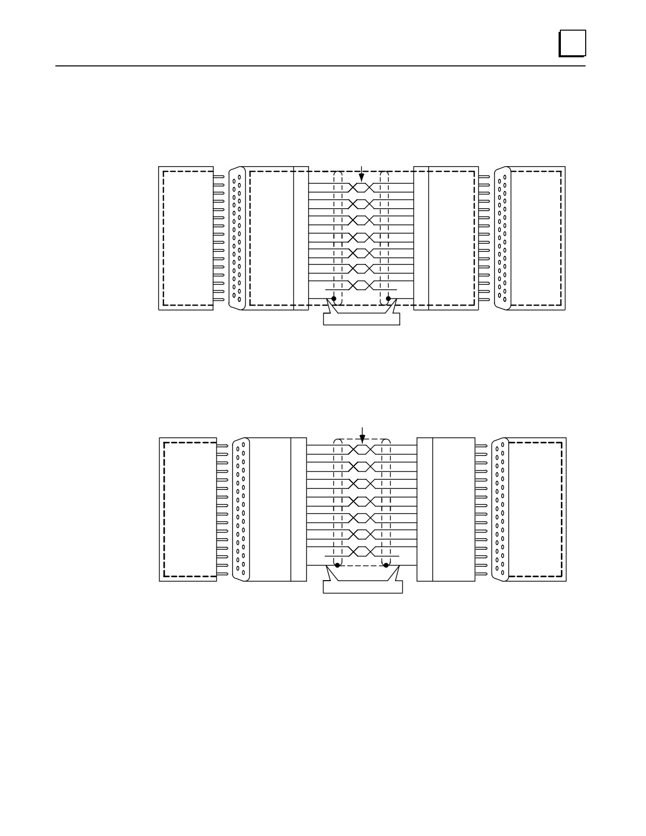
The following wiring diagrams show the wiring configuration for I/O expansion system
cables. Wiring diagrams are provided for both point-to-point cables and Wye cables.
TWISTED PAIRS, SHIELDED
a45525
PIN
(7 PAIRS)
PIN
DIODT
16
16
DIODT
DIODT/
17
17
DIODT/
SERIES
DIOCLK
24
24
DIOCLK
90-30
DIOCLK/
25
25
DIOCLK/
BASEPLATE
DRSEL
20
20
DRSEL
EXPANSION
WYE
DRSEL/
21
21
DRSEL/
PORT
CABLE
DPRERR
12
12
DPRERR
SINGLE
DPRERR/
13
13
DPRERR/
OR
CONNECTOR
END
DRMRUN
8
8
DRMRUN
DRMRUN/
9
9
DRMRUN/
WYE
CABLE
DPFRAME
2
2
DPFRAME
DOUBLE
DPFRAME/
3
3
DPFRAME/
CONNECTOR
0V
7
7
0V
END
NC
NC
FGND
1
1
FGND
25-PIN
25-PIN
SHIELD DRAIN WIRE
25-PIN
25-PIN
MALE
FEMALE
MALE
FEMALE
METALIZED SHELL
METALIZED SHELL
NOTE:
Bold dashed line shows continuous (100%) shielding when metallized shell connectors are plugged together.
Figure 10-17. Point-To-Point Cable Wiring for Continuous Shield Custom Length Cables
TWISTED PAIRS, SHIELDED
a45527
(7 PAIRS)
PIN
PIN
DIODT
16
16
DIODT
DIODT/
17
17
DIODT/
DIOCLK
24
24
DIOCLK
DIOCLK/
25
25
DIOCLK/
SERIES
DRSEL
20
20
DRSEL
WYE
90-30
DRSEL/
21
21
DRSEL/
CABLE
BASEPLATE
DRPERR
12
12
DRPERR
EXPANSION
DRPERR/
13
13
DRPERR/
SINGLE
PORT
DRMRUN
8
8
DRMRUN
CONNECTOR
DRMRUN/
9
9
DRMRUN/
END
OR
DFRAME
2
2
DFRAME
DFRAME/
3
3
DFRAME/
WYE
0V
7
7
0V
CABLE
NC
NC
FGND
1
1
FGND
25-PIN
25- PIN
SHIELD DRAIN WIRE
25- PIN
25- PIN
FEMALE
MALE
MALE
FEMALE
Figure 10-18. Point-To-Point Cable Wiring Diagram for Applications Requiring Less Noise
Immunity
GFK-0356P
Chapter 10 Cables
10-29
10
TWISTED SHIELDED
a47076
PIN
PAIRS
PIN
DIODT
16
16
DIODT
Î
ÎÎ
DIODT/
17
17
DIODT/
DIOCLK
24
24
DIOCLK
CABLE
Î
DIOCLK/
25
25
DIOCLK/
ÎÎ
TO
DRSEL
20
20
DRSEL
DOWNSTREAM
Î
DRSEL/
21
21
DRSEL/
ÎÎ
REMOTE
RACK
DRPERR
12
12
DRPERR
EXPANSION
Î
DRPERR/
13
13
DRPERR/
ÎÎ
BASEPLATE
OR
DRMRUN
8
8
DRMRUN
CONNECTOR
Î
DRMRUN/
9
9
DRMRUN/
ÎÎ
TERMINATION
PLUG
DPFRAME
2
2
DPFRAME
DPFRAME/
3
3
DPFRAME/
Î
ÎÎ
0V
7
7
0V
Î
ÎÎ
NC
NC
FGND
1
1
FGND
Î
NC
ÎÎ
25-PIN
25-PIN
25-PIN
25-PIN
MALE
FEMALE
MALE
FEMALE
Metallized Shell
Metallized Shell
Metallized Shell
Metallized Shell
SHIELD DRAIN WIRE
OR
CUT PIN 1 HERE IN
SHIELD DRAIN WIRE
NOT CONNECTED
FACTORY MADE WYE CABLES
ONLY FOR REMOTE BASEPLATES IC693CHS393E,
IC693CHS399D (AND EARLIER REVISIONS OF EACH)
PIN
16
DIODT
17
DIODT/
Î
24
DIOCLK
25
DIOCLK/
20
DRSEL
Î
21
DRSEL/
12
DRPERR
Î
CABLE
13
DRPERR/
FROM
8
DRMRUN
Î
UPSTREAM
RACK
9
DRMRUN/
2
DPFRAME
Î
3
DPFRAME/
7
0V
Î
NC
1
FGND
Î
25-PIN
Î
25-PIN
MALE
FEMALE
Metallized Shell
Metallized Shell
NOTE:
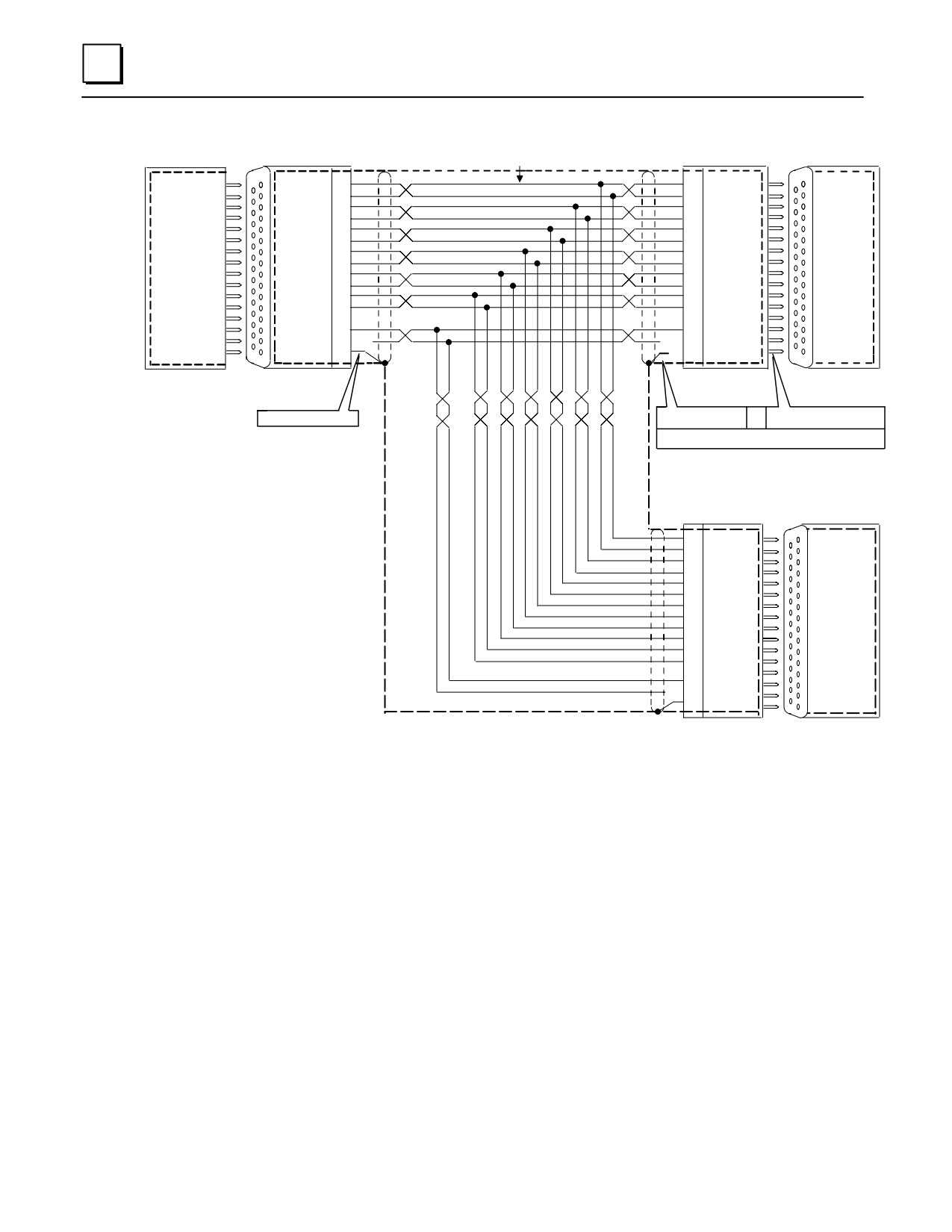
Bold dashed line shows continuous (100%) shielding when metallized shell connectors are plugged together.
Figure 10-19. Earlier Versions of Remote Baseplate Custom WYE Cable Wiring Diagram
Note
In remote baseplates, IC693CHS393E (and earlier) and IC693CHS399D (and earlier), it is
necessary to remove pin 1 of the mating cable where the cable plugs into the baseplate.
This means that when using a factory made Wye cable, IC693CBL300, you must break
pin 1 out of the male end where it plugs into the remote baseplate before using it with
one of these baseplates. Custom built Wye cables for these baseplates should be built using
Figure 10-20. See the section “Alert to Users of Early Remote Baseplate Versions” for
more details.
10-30
Series 90-30 PLC Installation and Hardware Manual - October 1999
GFK-0356P
10
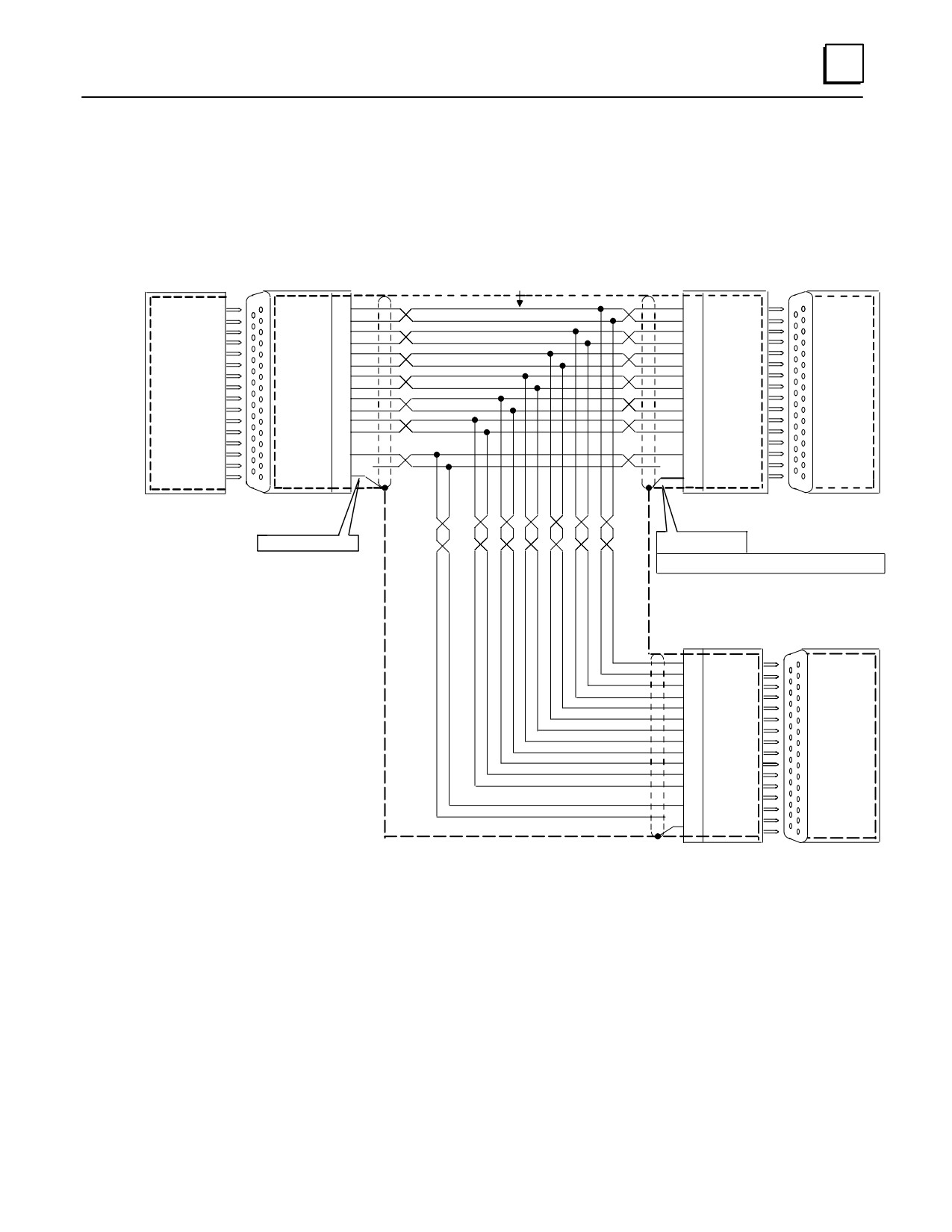
Remote baseplates IC693CHS393F (and later( and IC693CHS399E (and later) have a
change inside the baseplate which alleviates the need to remove pin 1 from the mating
cable. When using factory made Wye cable with these baseplates, it is not necessary to
remove pin 1 from the cable. Custom built Wye cables for these baseplates can be made
using either Figure 10-20 or Figure 10-21. Figure 10-21 shows how the factory made Wye
cable are made.
TWISTED SHIELDED
a47087
PIN
PAIRS
PIN
DIODT
16
16
DIODT
Î
ÎÎ
DIODT/
17
17
DIODT/
DIOCLK
24
24
DIOCLK
Î
ÎÎ
CABLE
DIOCLK/
25
25
DIOCLK/
TO
DRSEL
20
20
DRSEL
Î
ÎÎ
DOWNSTREAM
DRSEL/
21
21
DRSEL/
REMOTE
RACK
DRPERR
12
12
DRPERR
EXPANSION
Î
DRPERR/
13
13
DRPERR/
ÎÎ
BASEPLATE
OR
DRMRUN
8
8
DRMRUN
CONNECTOR
Î
DRMRUN/
9
9
DRMRUN/
ÎÎ
TERMINATION
PLUG
DPFRAME
2
2
DPFRAME
Î
DPFRAME/
3
3
DPFRAME/
ÎÎ
0V
7
7
0V
Î
ÎÎ
NC
NC
FGND
1
1
FGND
Î
ÎÎ
25-PIN
25-PIN
25-PIN
25-PIN
MALE
FEMALE
MALE
FEMALE
Metallized Shell
Metallized Shell
Metallized Shell
Metallized Shell
SHIELD DRAIN WIRE
SHIELD DRAIN WIRE
CONNECTED
FOR REMOTE BASEPLATES IC693CHS393F,
IC693CHS399E (AND EARLIER REVISIONS OF EACH)
PIN
16
DIODT
17
DIODT/
Î
24
DIOCLK
25
DIOCLK/
Î
20
DRSEL
21
DRSEL/
DRPERR
Î
CABLE
12
13
DRPERR/
FROM
Î
UPSTREAM
8
DRMRUN
9
DRMRUN/
RACK
2
DPFRAME
Î
3
DPFRAME/
Î
7
0V
NC
Î
1
FGND
25-PIN
Î
25-PIN
MALE
FEMALE
Metallized Shell
Metallized Shell
NOTE:
Bold dashed line shows continuous (100%) shielding when metallized shell connectors are plugged together.
Figure 10-20. Current Remote baseplate (IC693CHS393/399) Custom Wye Cable Wiring
Diagram
GFK-0356P
Chapter 10 Cables
10-31
10
Application Examples
Expansion System Cable Connections
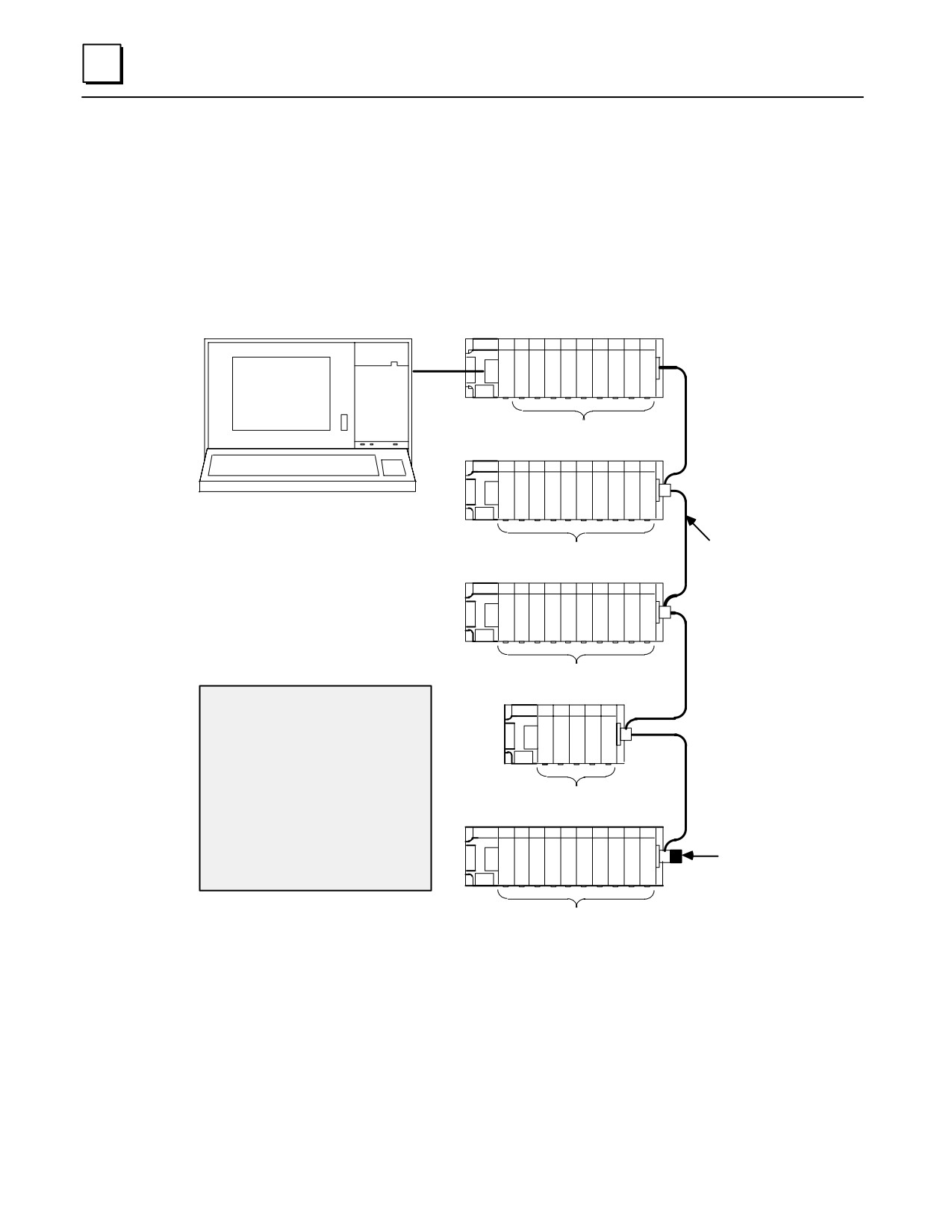
The following example shows cable connections in a system that has expansion
baseplates but no remote baseplates.
PROGRAMMER
CPU BASEPLATE
a47057
ÎÎÎÎÎ
SERIAL
ÎÎ
C
P
ÎÎÎÎÎ
ÎÎ
U
NOTE
TOTAL MAXIMUM
ÎÎÎÎÎ
ÎÎÎÎÎÎÎÎ
DISTANCE FROM
DISCRETE/ANALOG/OPTION
CPU BASEPLATE
ÎÎÎÎÎÎ
TO LAST EXPANSION
ÎÎÎÎÎÎÎÎÎÎ
EXPANSION BASEPLATE
BASEPLATE IS
50 FEET (15 METERS)
ÎÎÎÎÎÎÎÎÎÎ
ÎÎ
Î
ÎÎÎÎÎÎÎÎÎÎ
ÎÎ
Î
ÎÎÎÎÎÎÎÎ
I/O EXPANSION CABLES
DISCRETE/ANALOG/OPTION
IC693CBL300, 3 FT. (1 METER)
IC693CBL301, 6 FT. (1.8 METERS)
EXPANSION BASEPLATE
IC693CBL302/314, 50 FT. (15 METERS
IC693CBL312, 0.5 FT. (.15 METERS)
ÎÎ
Î
IC693CBL313, 25 FT. (8 METERS)
* See NOTE
ÎÎ
Î
ÎÎÎÎÎÎÎÎ
DISCRETE/ANALOG/OPTION
EXPANSION BASEPLATE
*NOTE
ÎÎÎ
Each signal pair on the I/O bus must
be terminated at the end of the I/O
ÎÎÎ
bus with120 ohm resistors. This ter-
ÎÎ
mination can be done with the I/O
Bus Terminator Plug (IC693ACC307),
DISCRETE/ANALOG/OPTION
by using the 50 foot (15 meter) cable
(IC693CBL302/314) with built-in termi-
EXPANSION BASEPLATE
I/O BUS
nating resistors, or by building a cus-
tom cable with the resistors installed
Î
Î
TERMINATOR
in the connector at the end of the bus.
PLUG (See *NOTE)
Î
IC693ACC307
ÎÎÎÎÎÎÎÎ
DISCRETE/ANALOG/OPTION
Figure 10-21. Example of Connecting Expansion Baseplates
10-32
Series 90-30 PLC Installation and Hardware Manual - October 1999
GFK-0356P
10
Remote and Expansion System Cable Connection Example
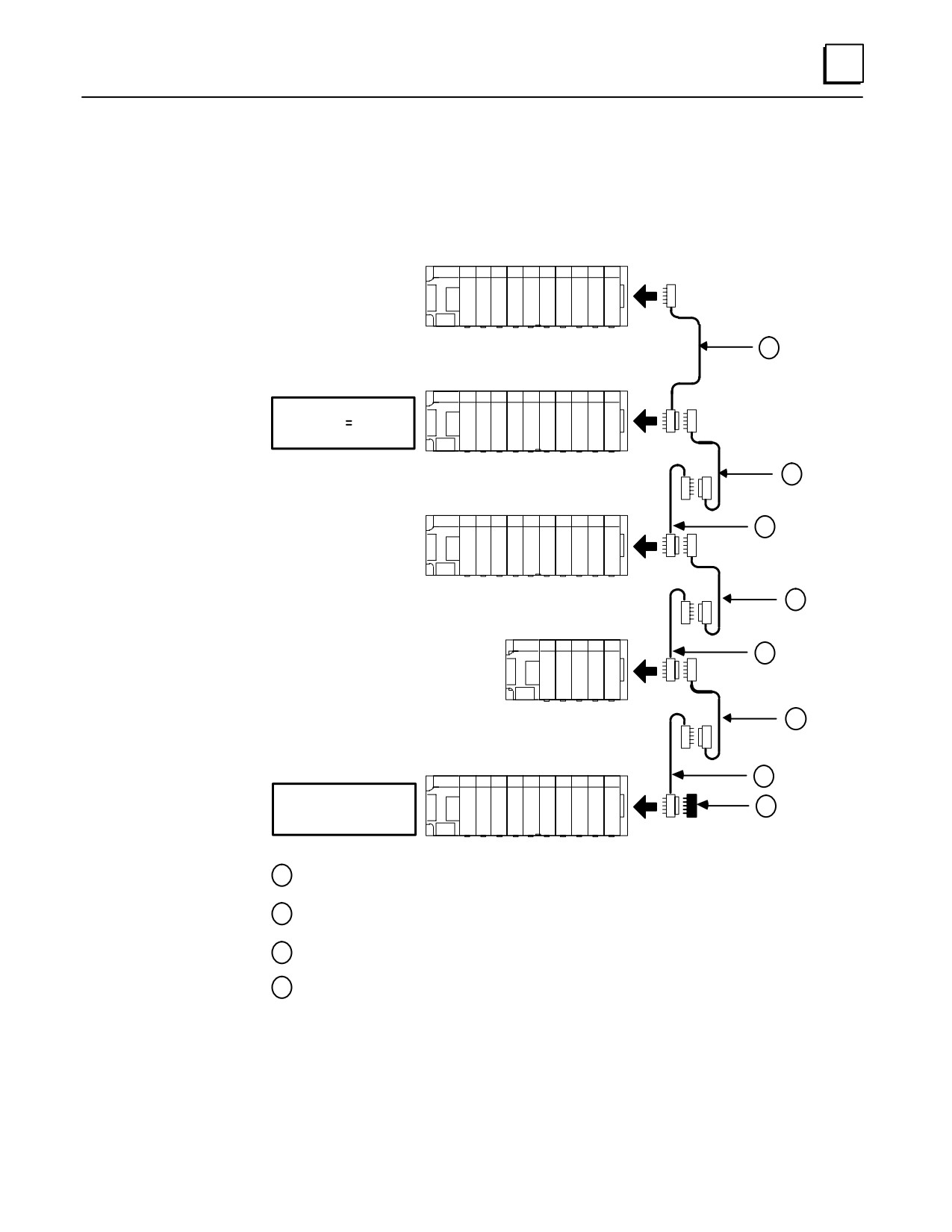
The following example shows cable connections in a system that includes both remote
and expansion baseplates. A system can have a combination of remote and expansion
baseplates as long as the distance and cable requirements are followed.
CPU BASEPLATE
a44965A
CPU
C
BASEPLATE
P
IC693CHS391/397
U
1
EXPANSION
BASEPLATE
EXPANSION BASEPLATE
IC693CHS392/398
MAXIMUM DISTANCE
FROM CPU 50 FEET
(15 METERS)
2
REMOTE BASEPLATE
3
REMOTE
BASEPLATE
IC693CHS393/399
2
REMOTE BASEPLATE
REMOTE
ÎÎ
3
BASEPLATE
ÎÎ
IC693CHS393/399
ÎÎÎ
2
REMOTE
BASEPLATE
REMOTE BASEPLATE
IC693CHS393/399
3
MAXIMUM DISTANCE
FROM CPU= 700 FEET
4
(213 METERS)
1
Standard Wye Cable
2
Custom Built Point-to-Point Cable
3
IC693CBL300 Standard Wye Cable, Used as Wye Jumper
4
IC693ACC307 Bus Terminator
Figure 10-22. Example of Connecting Expansion and Remote Baseplates
GFK-0356P
Chapter 10 Cables
10-33
10
IC693CBL303
Hand-Hand Programmer and Converter (IC690ACC900) Cable
Function of cable
The Hand-Held Programmer cable provides the connections that allow the Hand-Held
Programmer and the Programmable Logic Controller to communicate. This cable also
provides the power connections for the HHP, and a signal which indicates to the PLC
that the HHP is attached to the PLC serial port. It can also be used to connect the
RS-485 serial port on the PLC to the RS-422/RS-485 to RS-232 converter (IC690ACC900).
Cable Specifications
The prewired cable (IC693CBL303) is 6 feet (2 meters) long. If a different length cable is
required for connection to the converter, refer to the information below for specifications
and wiring information.
This information is essential if you intend to build your own cable. The recommended
cable types for this cable are listed below and depend on the length of the cable.
Specifications for IC693CBL303 Prewired cable
Item
Description
Connectors
15-pin male, D-SubminiatureType, Canon DA15S (solder pot)
Same connector is on
bothends
Hood
AMP 207470-1 connector shell
Hardware kit
AMP 207871-1 Kit includes 2 metric screws and 2 screw clips
Cable Type
Belden 9508:
AWG #24 (.22 mm2)
CableLength
6 feet (2 meters)
Wire Types for Custom Cables
Cable Length
Wire Size
CatalogNumber
30 feet (10m)
22 (.36 mm2)
Belden 9309
>30 (10m) feet to
22 (.36 mm2)
Same as for 30 feet. In addition, the+5 VDC logic power source for the
980 feet (300m)
converter cannot be supplied by the PLC. It must be provided by an
external power supply connected to the +5V and SG pins at the converter
end of the connector. The +5V pin at the PLC connector must not be con-
nected to the cable. The +5V and SG connections from the power supply
must be isolated from its own power line ground connection. Be sure that
there is no connection between the external supply and the PLC except the
SG cable connection.
1.
Catalog numbers are provided as suggestions only. Any cable having the same electrical characteristics is
acceptable. It is strongly recommended that you use stranded wire. Since it is sometimes hard to find a
cable with the desired number of twisted pairs (the Belden 9309 has an extra pair), you may end up with a
cable with extra pairs.
2.
A greater cable length between the PLC and the converter increases the possibility of noise coupling into
the data and converter logic power circuits within the cable. The cable should be as short as possible in
noisy environments. In extreme cases, additional noise protection measures, such as double-shielded
cables, may be required.
10-34
Series 90-30 PLC Installation and Hardware Manual - October 1999
GFK-0356P
10
Wiring Diagram
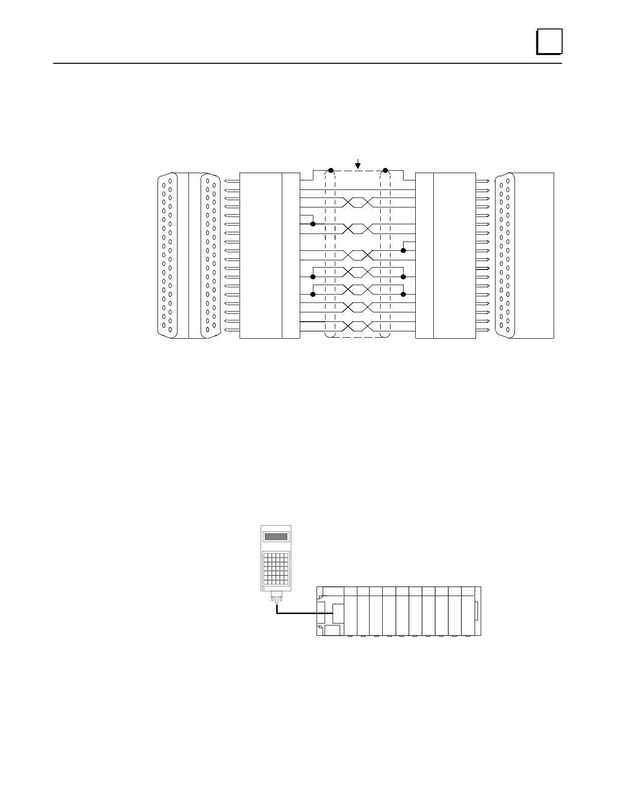
The following wiring diagram applies to the IC693CBL303 cable and to custom-built
cables.
RS-422
RS-232/RS-485
TWISTED SHIELDED PAIRS
a44750
CONVERTER
(IC690ACC900)
PIN
PIN
SHLD
1
1
SHLD
Î
Î
ÎÎ
ATTCH
4
4
ATTCH
DCD (A)
2
2
DCD (A)
Î
Î
ÎÎ
DCD (B)
3
3
DCD (B)
RT
9
Î
Î
ÎÎ
RD (A’)
10
12
SD (A)
Î
Î
RD (B’)
11
13
SD (B)
ÎÎ
SERIES
9
RT
90 PLC
Î
Î
SD (A)
12
10
RD (A’)
ÎÎ
SD (B)
13
11
RD (B’)
RS-422
Î
Î
ÎÎ
PORT
+5V
5
5
+5V
Î
Î
ÎÎ
0V
7
7
0V
Î
Î
ÎÎ
RTS (A)
6
15
CTS (A’)
Î
Î
RTS (B)
14
8
CTS (B’)
ÎÎ
CTS (A’)
15
6
RTS (A)
Î
Î
CTS (B’)
8
14
RTS (B)
ÎÎ
25-PI
15-PIN
15-PIN
15-PIN
15-PIN
FEMALE
FEMALE
MALE
MALE
FEMALE
RS-232 PORT
RS-485 PORT
PINS 9 AND 10 ARE JUMPERED AT BOTH ENDS OF CABLE TO CONNECT TERMINATING
NOTE:
RESISTORS FOR THE RD SIGNAL WHICH IS INSIDE THE PLC POWER SUPPLY.
Figure 10-23. Wiring Connections for IC693CBL303 and Custom-Built Cables
Connecting the Cable
Attach the 15-pin male D connector to the serial port connector on the PLC power
supply.
Attach the D connector on the other end to the mating connector on the HHP.
These connections are shown in the following figure.
a47062
HAND-HELD
PROGRAMMER
SERIES 90-30
Î
Î
Î
Î
ÎÎ
ÎÎÎÎÎ
C
CABLE
ÎPÎÎÎÎÎÎÎÎ
(IC693CBL303)
ÎÎUÎÎÎÎÎÎÎÎ
ÎÎÎÎÎÎÎÎÎÎÎ
Figure 10-24. Hand-Held Programmer Cable Connection to a Series 90-30 PLC
GFK-0356P
Chapter 10 Cables
10-35
10
IC693CBL304/305
Port Expansion (WYE) Cables for PCM, ADC, and CMM
Function of cable
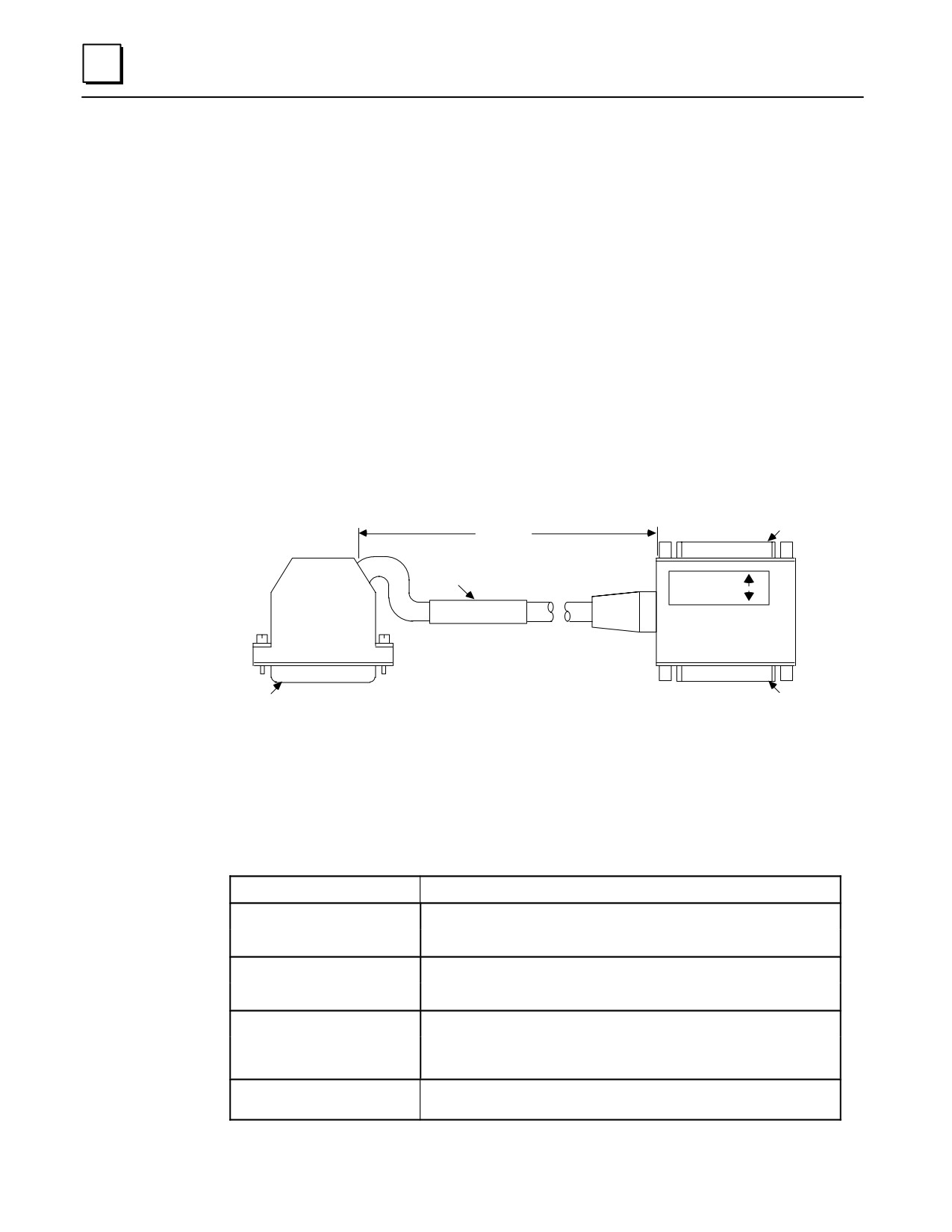
A WYE cable (IC693CBL304 for PCM300; IC693CBL305 for PCM301/311, ADC311, CMM311,
AD693CMM301, and SLP300) is supplied with each PCM, ADC, and CMM module. The
WYE cable is used to separate two ports available on a single physical connector; the cable
separates the RS-232 from the RS-485 signals. In addition, the WYE cable allows cables used
with the Series 90-70 PCM to be fully compatible with the Series 90-30 PCM. The WYE
cable and cable connections are shown below and on the following page.
Each WYE cable is 1 foot in length and has a right angle male connector on one end that
connects to the PCM module. The other end has a dual female connector with one
connector for port 1 and the other for port 2.
a44225
RS-232
25-PIN FEMALE
CONNECTOR PIN 1
1 FOOT
(+2.0 INCH, -0 INCH)
ÎÎ
LABEL
PORT 1
PORT 2
ÎÎ
Î
PCM COMM. CABLE
IC693CBL305B
ÎÎ
RS-232
RS-232/RS-485
PIN 1
PIN 1
25-PIN MALE
25-PIN FEMALE
CONNECTOR
CONNECTOR
Figure 10-25. Wye Cable
Cable Specifications
Cable Length
1 foot (0.3 meters)
25 PinMale Connector:
Crimp Plug = Amp 207464-1; Pin = Amp 66506-9
Solder Plug = Amp 747912-2
25 Pin FemaleConnector:
Crimp Receptacle = Amp 207463-2; Pin = Amp 66504-9
Solder Receptacle = Amp 747913-2
ConnectorShell:
Kit - Amp 207908-7
Separate Shell = Amp 207345-1;
Male Screw Retainer = Amp 205980-1
Cable Type
27 conductor cable, 28 AWG (.09 mm2), with overall shield, extra
flexible
10-36
Series 90-30 PLC Installation and Hardware Manual - October 1999
GFK-0356P
10
Wiring Information
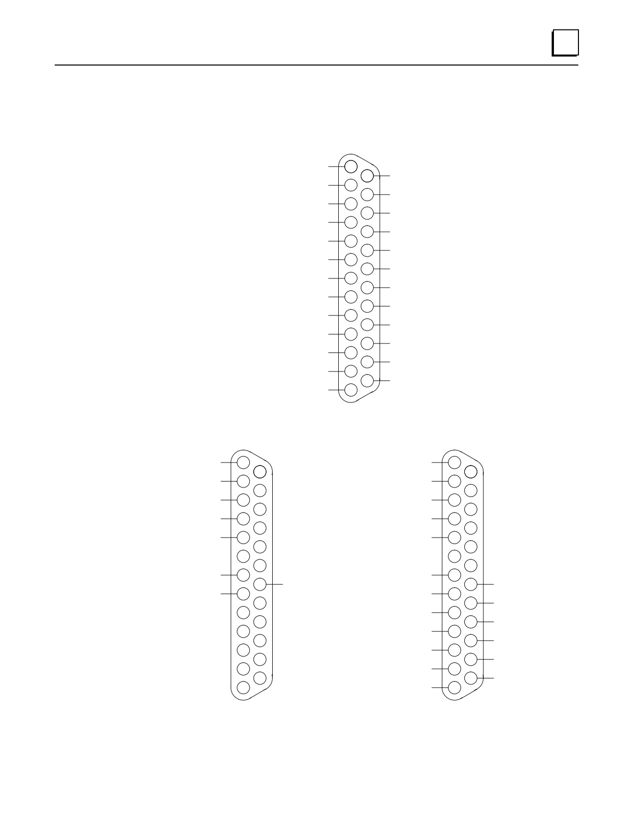
The following figure shows the pin configuration for each of the connectors on the WYE
cable.
a44357
ÎÎ
SHIELD
ÎÎ114Î
RS-232 TD ( PORT 2 )
( PORT 1 ) RS-232 TD
ÎÎ2ÎÎ
15
RS-232 CTS ( PORT 2 )
( PORT 1 ) RS-232 RD
3
Î
16
RS-232 RD ( PORT 2 )
( PORT 1 ) RS-232 RTS
4
17
RS-232 DTR ( PORT 2 )
( PORT 1 ) RS-232 CTS
5
18
RS-232 DCD ( PORT 2 )
NO CONNECTION
6
19
RS-232 RTS ( PORT 2 )
SIGNAL GROUND
7
20
RS-232 DTR ( PORT 1 )
( PORT 1 ) RS-232 DCD
8
21
RS-485 SD ( B ) (PORT 2 )
( PORT 2 ) RS-485 SD ( A )
9
22
RS-485 RTS ( B ) ( PORT 2 )
( PORT 2 ) RS-485 RTS ( A )
10
23
RS-485 CTS ( B’ ) ( PORT 2 )
( PORT 2 ) RS-485 CTS ( A’ )
11
24 Î
TERMINATION ( RD ) (PORT 2)
( PORT 2 ) TERMINATION ( CTS )
Î12
25
RS-485 RD ( B’ ) ( PORT 2 )
ÎÎÎ13
Î
( PORT 2) RS-485 RD ( A’ )
ÎÎ
MALE CONNECTOR
PORT 1
PORT 2
a44358
ÎÎ
ÎÎ
SHIELD
SHIELD
Î1ÎÎ
14
Î1ÎÎ
14
RS-232 TD
RS-232 TD
Î2ÎÎÎ
Î2ÎÎ
15
15
RS-232 RD
3
ÎÎ
RS-232 RD
3
ÎÎ
16
16
RS-232 RTS
4
RS-232 RTS
4
17
17
RS-232 CTS
5
RS-232 CTS
5
18
18
6
6
19
19
SIGNAL GROUND
7
SIGNAL GROUND
7
20
20
RS-232 DTR
RS-232 DTR
RS-232 DCD
8
RS-232 DCD
8
21
21
RS-485 SD ( B )
9
RS-485 SD ( A )
9
22
22
RS-485 RTS ( B )
10
RS-485 RTS ( A )
10
23
23
RS-485 CTS ( B’ )
11
RS-485 CTS ( A’ )
11
TERMINATION ( RD )
ÎÎ
Î24Î
12
TERMINATION ( CTS )
12
ÎÎ25ÎÎ
ÎÎÎ
Î RS-485 RD ( B’ )
RS-485 RD ( A’ )
Î13ÎÎ
Î13ÎÎ
Î
DUAL FEMALE CONNECTORS
Î
Figure 10-26. Wye Cable Connections
GFK-0356P
Chapter 10 Cables
10-37
10
The WYE cable is 1 foot in length and has a right angle male connector on one end that
connects to the PCM module. The other end has a dual female connector with one
connector for port 1 and the other for port 2.
In order to use an RS-232 cable on port 2 of the Series 90-30 PLC, either a special cable
must be made following the serial port pin assignments shown above or a WYE cable
must be used. The WYE cable allows use of standard Series 90-70 cables
(IC690CBL701/702/705) for the PCM or ADC. When installing the CMM module, use the
WYE cable in conjunction with cables that you build for the CMM module according to
directions in Chapter 8 of GFK-0582, the Series 90 PLC Serial Communications Manual.
10-38
Series 90-30 PLC Installation and Hardware Manual - October 1999
GFK-0356P
10
IC693CBL306/307
Extension Cables (50-Pin) for 32 Point Modules
Function of cable
This cable is used with 32 point High Density modules that have a 50-pin male Honda
connector mounted on the front of the module. The extension cables have a 50-pin
male connector on one end and a 50-pin female connector on the other end. This cable
provides a connection from the module to a connector mounted on a DIN-rail-mounted
terminal block assembly. This cable is wired pin-to-pin (That is, pin 1 to pin 1, pin 2 to
pin 2, etc.). The modules that use these cables are: IC693MDL652, IC693MDL653,
IC693MDL750, and IC693MDL751.
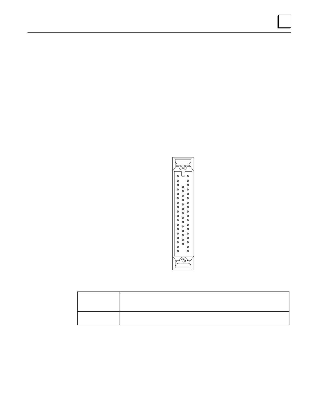
The connector on the module is oriented with the notch towards the top of the module
with pin 1 at the top of the the right row of pins as you are looking at it, as shown below:
a45149
33
1
19
32
50
18
Cable Specifications
Cable Length
IC693CBL306
3 feet (1 meter),
IC693CBL307
6 feet (2 meters)
Connectors
50-pin female Honda on end that connects to male connector on module.
50-pin male connector on end that connects to Connector InterfaceAssembly.
We recommend the use of a terminal block for connecting field wiring to the 50-pin
high-density I/O modules. The use of a connector interface provides a convenient
method of terminating field wiring to the modules.
Weidmuller Electrical and Electronic Connection Systems makes a suitable terminal
block assembly RS-MR 50 B, catalog number 912263 (female Honda connector). An
example of using an IC693CBL306 or 307 cable to connect a 32 point I/O module to one
of these terminal blocks is shown in the following figure.
GFK-0356P
Chapter 10 Cables
10-39
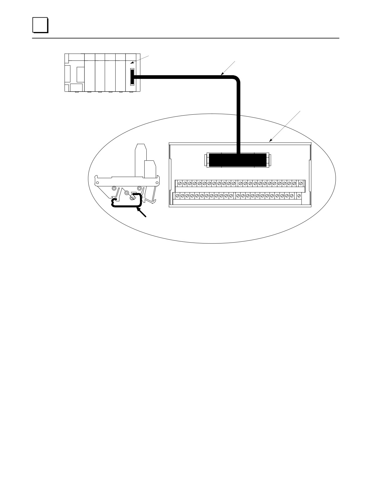
10
ÎÎÎÎÎÎÎÎ
50-Pin, 32-Point
I/O Module
Extension Cable
ÎÎÎÎÎÎÎÎ
a44838A
ÎÎÎÎÎÎÎÎ
ÎÎÎÎÎÎÎÎ
ÎÎÎÎÎÎÎÎ
SERIES 90-30 PLC
Weidmuller
Terminal BlocK
(DIN-Rail Mounted)
50
Î
Î
END
VIEW
Î1ÎÎÎÎÎÎÎ
26
27 28 29 30 31 32 33 34 35 36 37
38 39 40 41 42 43 44 45 46 47 48 49
50
ÎÎÎÎ
1
2
3
4
5
6
7
8
9
10 11 12
13 14 15 16 17 18 19 20 21 22 23 24
25
ÎÎ Î
TOP
Mounts on
VIEW
DIN-Rail
Figure 10-27.
32 Point I/O Module to Weidmuller Terminal Block Assembly
10-40
Series 90-30 PLC Installation and Hardware Manual - October 1999
GFK-0356P
10
IC693CBL308/309
I/O Cables (50-Pin) for 32 Point Modules
Function of cable
This cable is used with 32 point High Density modules that have a 50-pin Honda
connector mounted on the front of the module. The modules that use these cable are:
IC693MDL652, IC693MDL653, IC693MDL750, and IC693MDL751.
The I/O cables have a female connector on one end, and stripped and tinned wires on
the other end. Each of the stripped and tinned wires has a label attached to it for ease of
identification. The numbers on these labels correspond with the pin number of the
connector wired to the opposite end.
Specifications
Cable Length
IC693CBL308
3 feet (1 meter)
IC693CBL309
6 feet (2 meters)
Connectors
50-pin female Honda on end that connects to male connector on module. Opposite end
has stripped and tinned labeled wires for connection to Connector InterfaceAssembly
Wiring Information
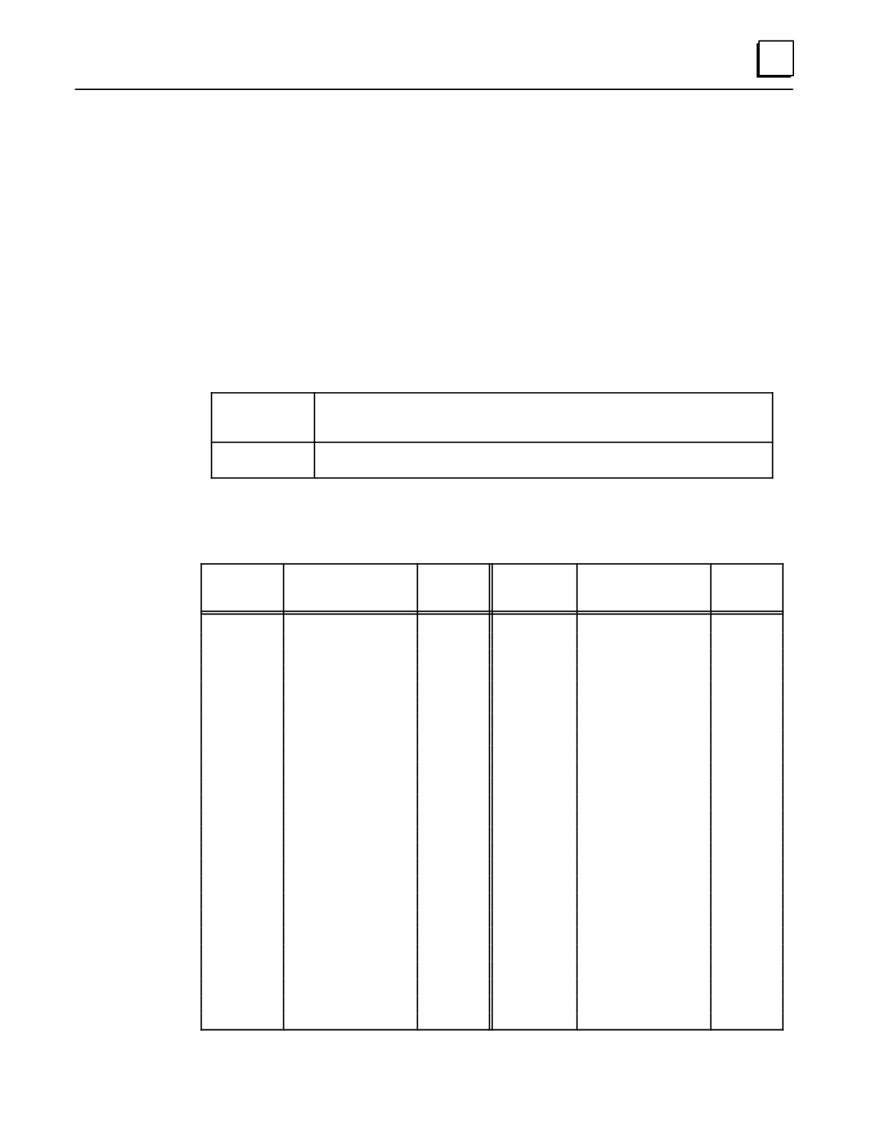
Table 10-3. Wire List for 32 Point I/O Cables
Connector
Label
Connector
Label
Pin
Number
Pin
Number
Color Code
Color Code
Number
Loose End
Number
Loose End
1
Black
1
26
White/Black
iolet
26
2
Brown
2
27
White/Black/Gray
27
3
Red
3
28
White/Brown/Red
28
4
Orange
4
29
White/Brown/Orange
29
5
Yellow
5
30
White/Brown
ellow
30
6
Green
6
31
White/Brown/Green
31
7
Blue
7
32
White/Brown/Blue
32
8
Violet
8
33
White/Brown/
olet
33
9
Gray
9
34
White/Brown/Gray
34
10
White
10
35
White/Red/Orange
35
11
White/Black
11
36
White/Red
ellow
36
12
White/Brown
12
37
White/Red/Green
37
13
White/Red
13
38
White/Red/Blue
38
14
White/Orange
14
39
White/Red/
olet
39
15
White/
ellow
15
40
White/Red/Gray
40
16
White/Green
16
41
White/Orange
ellow
41
17
White/Blue
17
42
White/Orange/Green
42
18
White/
iolet
18
43
White/Orange/Blue
43
19
White/Gray
19
44
White/Orange/
olet
44
20
White/Black/Brown
20
45
White/Orange/Gray
45
21
White/Black/Red
21
46
White/Yellow/Green
46
22
White/Black/Orange
22
47
White/Yellow/Blue
47
23
White/Black
ellow
23
48
White/
ellow/
iolet
48
24
White/Black/Green
24
49
White/Yellow/Gray
49
25
White/Black/Blue
25
50
White/Green/Blue
50
GFK-0356P
Chapter 10 Cables
10-41
10
IC693CBL310
I/O Interface Cable (24-Pin) for 32 Point Modules
Note: This cable is obsolete. Please use IC693CBL327 and IC693CBL328. See
the data sheet for these cables for details. The replacement cables have right-
angle connectors to reduce the clearance space required in front of the PLC.
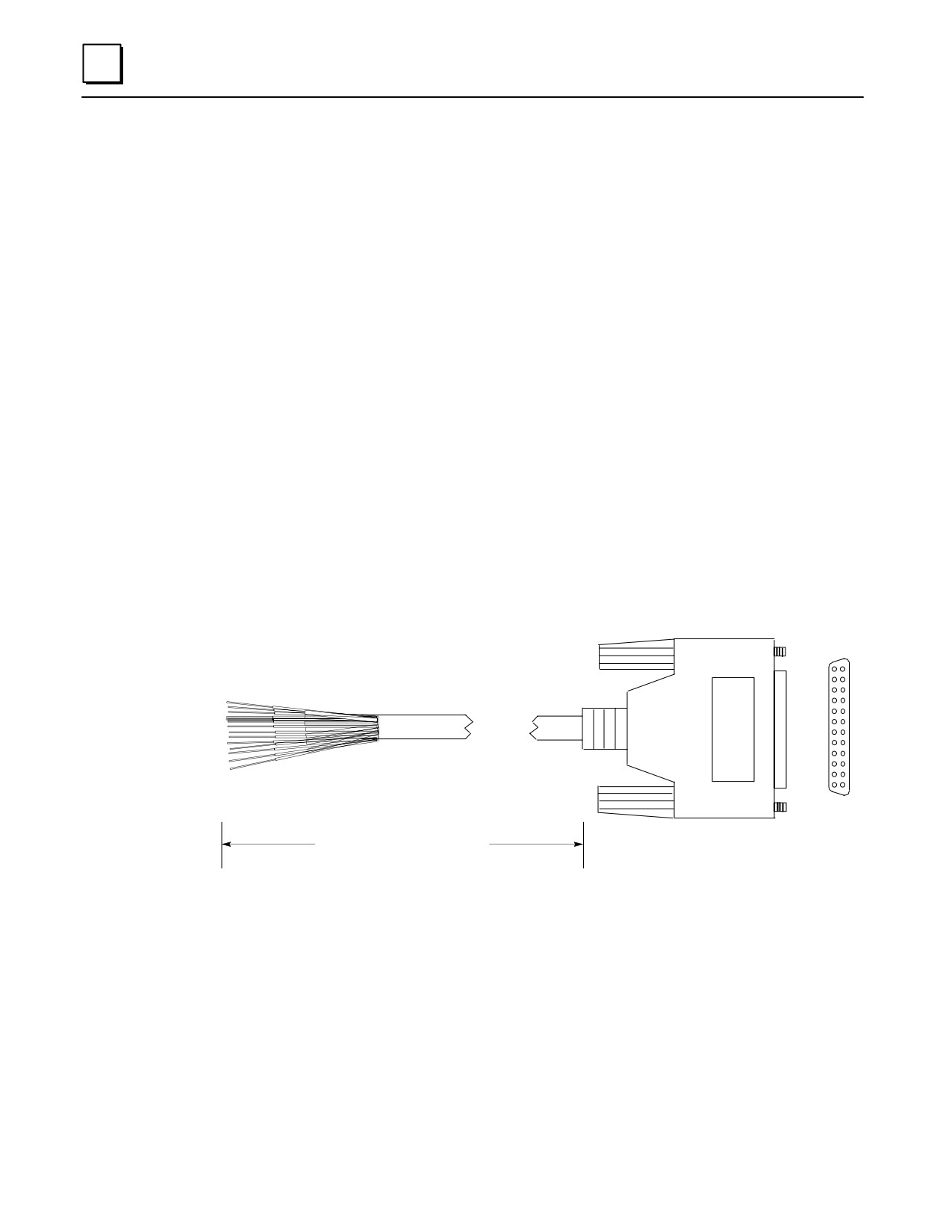
Function of cable
This 10’ (3 meter0 prewired cable was used with all Series 90-30 high-density (32 point) I/O
modules that use the Fujitsu 24-pin user I/O connector. Each of these modules has two of
these connectors mounted side-by-side. I/O Interface cables have a 24-pin female connector
on one end for connection to the module, and stripped and tinned wires on the other end.
Catalog numbers for 32 point modules having two 24-pin connectors are: IC693MDL654,
IC693MDL655, IC693MDL752, and IC693MDL753.
Connections to module input circuits are made from the user’s input devices to two male
(pin-type) 24-pin connectors (Fujitsu FCN-365P024-AU) mounted on the front of the
module. The connector mounted on the right of the module (front view) interfaces with
groups A and B; the connector on the left side of the module interfaces with groups C and
D. If a different length cable is required for connections to these modules, you can build
your own cable (information on building your own cable is found in the data sheet for cable
IC693CBL315).
A1
B1
A12
B12
Length = 10’ (3 meters)
Connector: FujitsuFCN-365S024-AU
Figure 10-28. IC693CBL310 Cable
10-42
Series 90-30 PLC Installation and Hardware Manual - October 1999
GFK-0356P