Omron IPC Machine Controller Industrial Panel PC / Industrial Box PC. Software User’s Manual (Industrial PC Platform NY-series) - page 16
10 Communications Setup
10-3 Connection with Other Controllers or
Slaves
This section shows the connection configurations that are used between Controllers and between Con-
trollers and slaves.
10-3-1
Connection Configurations between Controllers
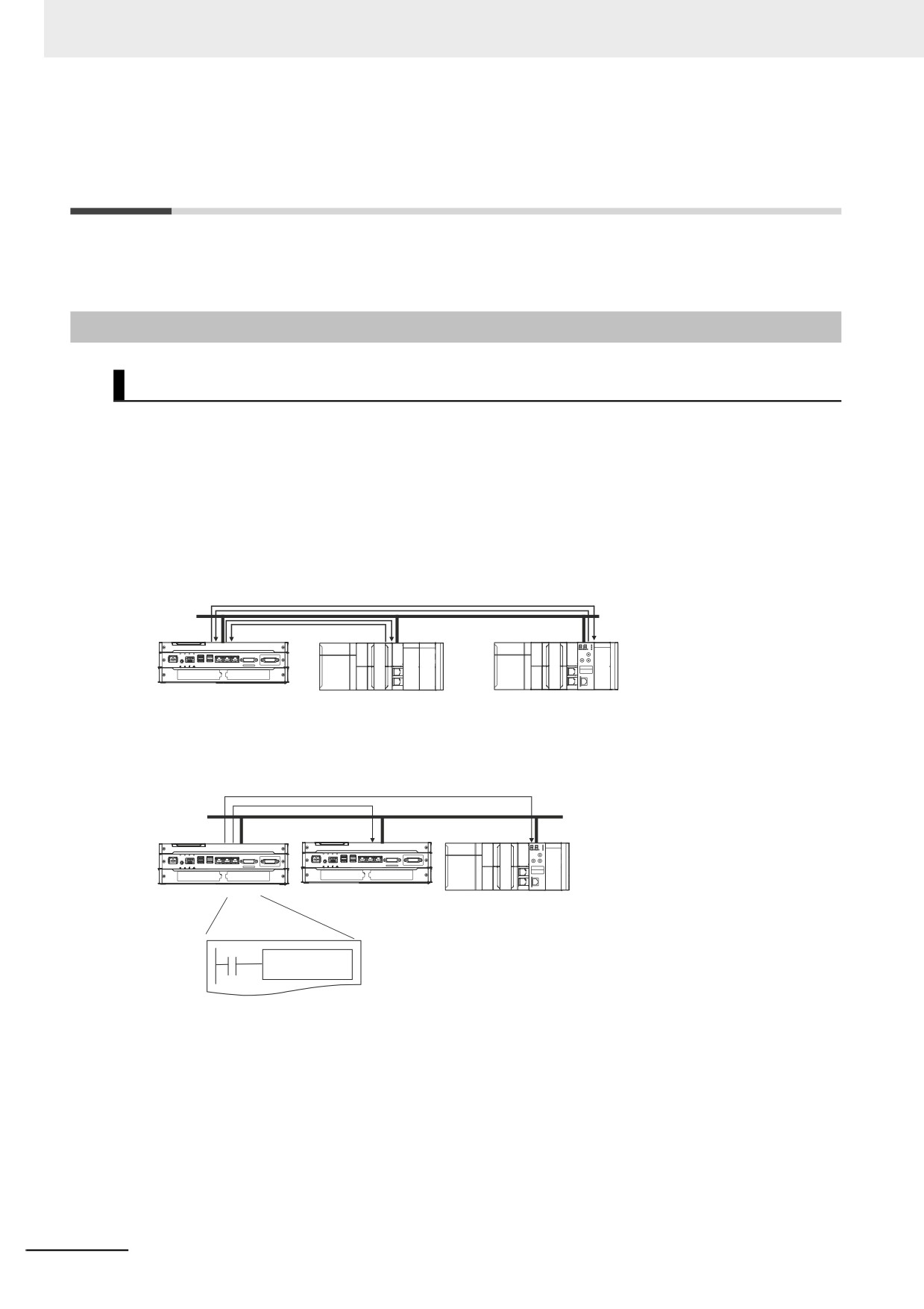
EtherNet/IP
You can use the built-in EtherNet/IP port.
For information on the built-in EtherNet/IP port, refer to the NY-series Industrial Panel PC / Industrial
Box PC Built-in EtherNet/IP Port User's Manual (Cat. No. W563).
z Tag Data Links
You can create tag data links between NJ/NX/NY-series Controllers on an EtherNet/IP network.
EtherNet/IP
z Message Communications
You can send CIP messages from the user program.
EtherNet/IP
CIP communications
instruction
10-6
10 Communications Setup
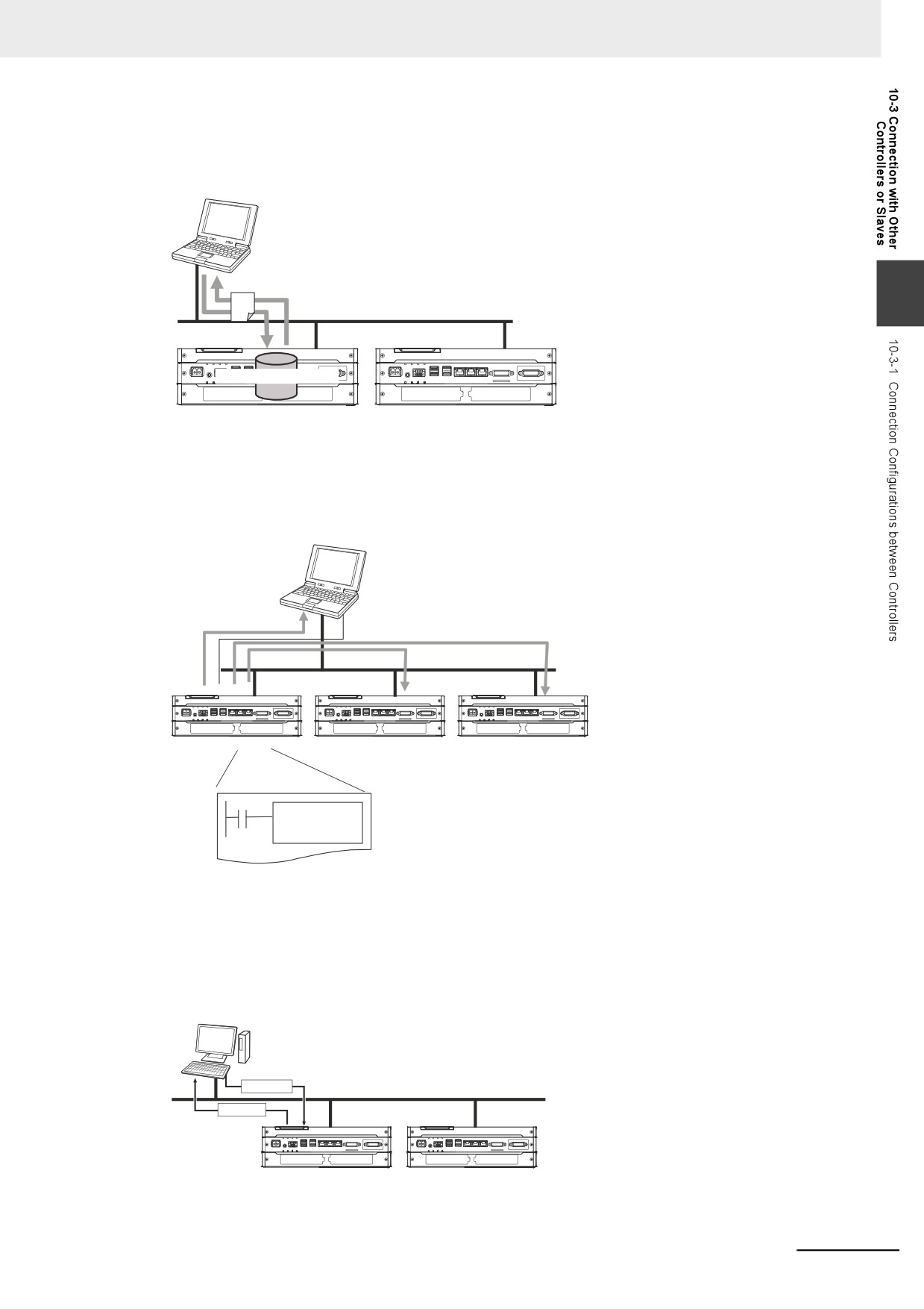
z Sending and Receiving Files
You can send and receive files on the Virtual SD Memory Card in the NY-series Controller from an
FTP client application.
FTP client application
Sending and Receiving Files
10
EtherNet/IP
FTP server
Virtual SD Memory Card
z Socket Services
You can directly use TCP or UDP from the user program to send and receive any data with remote
nodes between a host computer and the Controller, or between Controllers. The socket services are
supported only for the built-in EtherNet/IP ports.
Communications
EtherNet/IP
Socket service
instruction
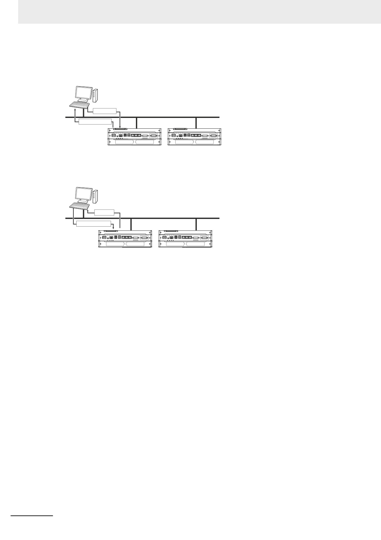
z Specifying Host Names
You can use the DNS client or set up your Hosts so that you can specify the IP address of the SNMP
manager or the target destination of a socket instruction or CIP communications instruction with a
host name instead of an IP address.
Example: Setting Host Names on the DNS Server
DNS server
IP address
EtherNet/IP
Host name
DNS client
10-7
10 Communications Setup
z Obtaining an IP Address When the Power Is Turned ON
You can obtain an IP address for the built-in EtherNet/IP port from the BOOTP server when the
power supply is turned ON.
BOOTP server
IP address
EtherNet/IP
BOOTP commands
BOOTP client
z Specifying an SNMP Agent
Built-in EtherNet/IP port internal status information is provided to network management software
that uses an SNMP manager.
SNMP manager
Administration
information
EtherNet/IP
SNMP messages
SNMP agent
10-8
10 Communications Setup
10-3-2
Connection Configuration between Controllers and Slaves
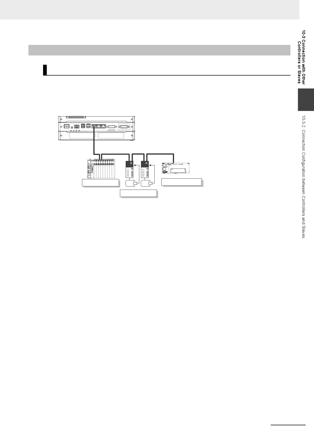
EtherCAT
High-speed, high-precision communications are possible with Servo Drives and general-purpose
slaves.
Refer to the NY-series Industrial Panel PC / Industrial Box PC Built-in EtherCAT Port User's Manual
10
(Cat. No. W562) for details.
EtherCAT
Slave Terminal
General-purpose slave
Servo Drives
10-9
10 Communications Setup
10-4 Connection with HMIs
This section shows the connection configurations used to connect HMIs to the NY-series Controller.
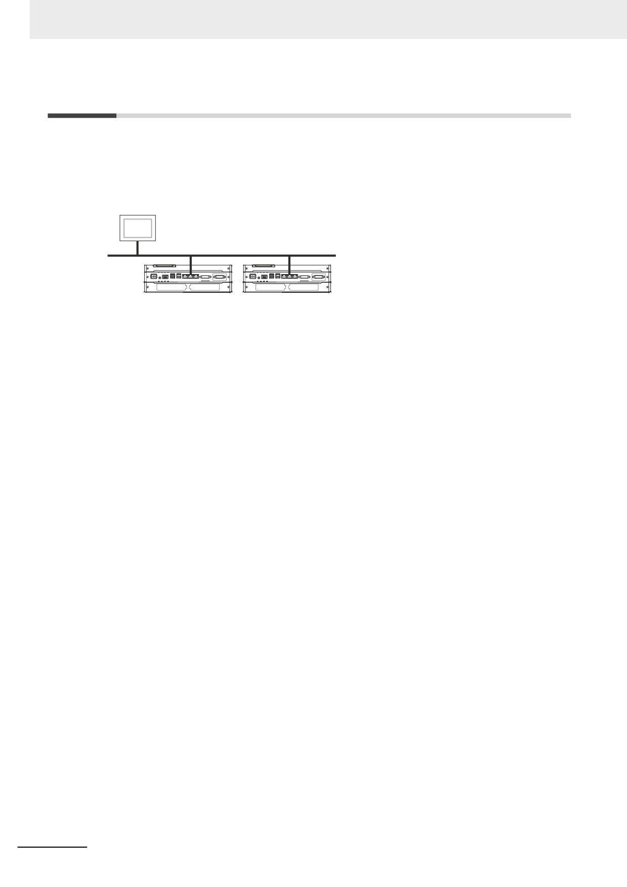
z EtherNet/IP
You can use a built-in EtherNet/IP port to connect to an HMI.
HMI
EtherNet/IP
Built-in EtherNet/IP port
Built-in EtherNet/IP port
For information on the built-in EtherNet/IP port, refer to the NY-series Industrial Panel PC / Industrial
Box PC Built-in EtherNet/IP Port User's Manual (Cat. No. W563).
10-10

Example of Actual Application
11
Procedures
This section describes the procedures that are used to actually operate an NY-series
Controller.
11-1 Example Application
11-2
11-1-1
System Configuration
11-2
11-1-2
Operation
11-2
11-2 Overview of the Example Procedure
11-3
11-2-1
Wiring and Settings
11-3
11-2-2
Software Design
11-3
11-2-3
Software Settings from the Sysmac Studio
11-4
11-2-4
Programming with the Sysmac Studio
11-8
11-2-5
Checking Operation and Starting Operation on the Actual System
11-9
11-1
11 Example of Actual Application Procedures
11-1
Example Application
This section describes an example application for an NY-series Controller.
11-1-1
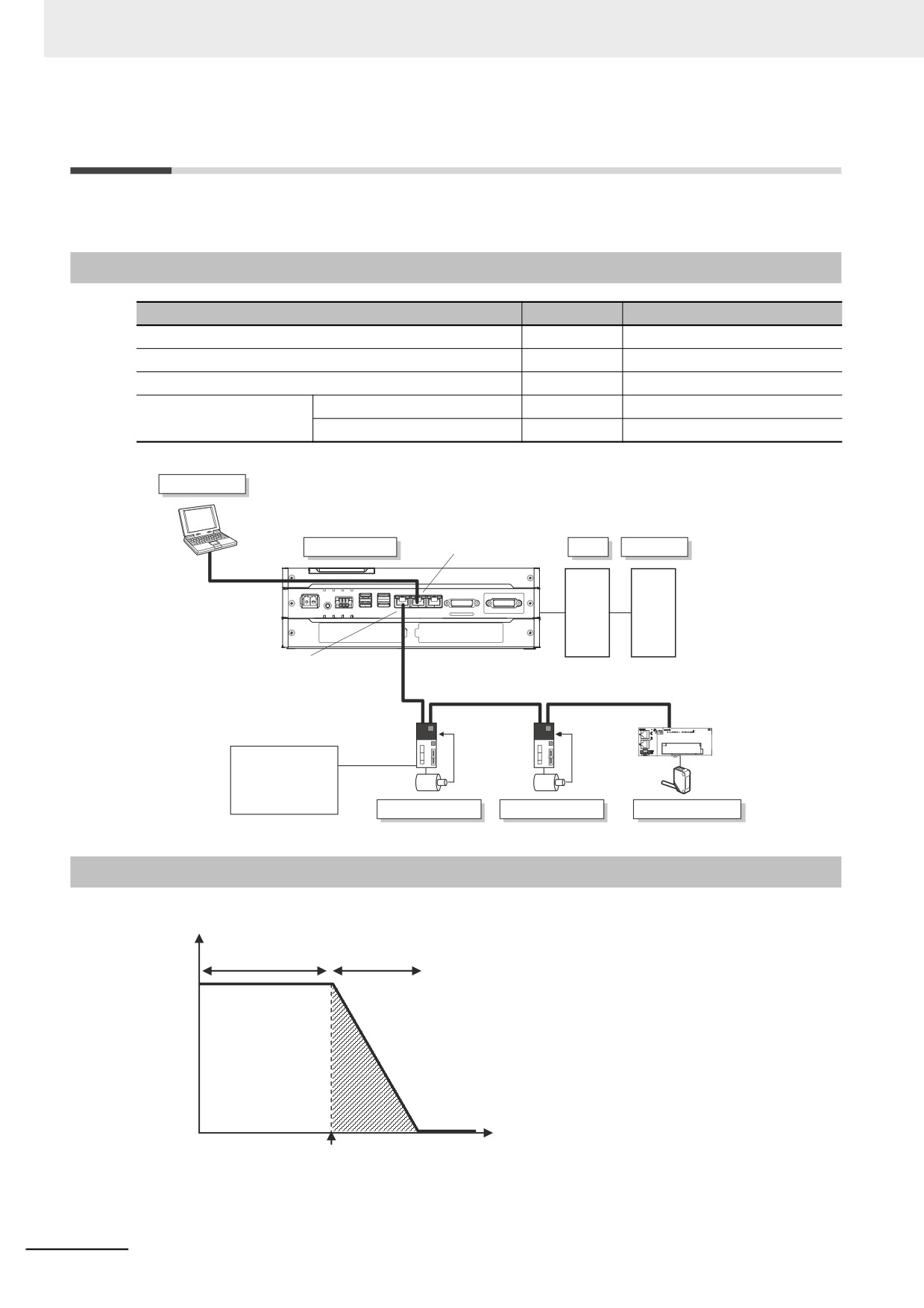
System Configuration
Unit name
Qty
Connected device
Power Supply
1
---
UPS (Uninterruptible Power Supply)
1
---
NY-series Industrial Box PC
1
---
EtherCAT slaves
Servo Drives (G5 EtherCAT)
2
---
I/O Terminal
1
Photoelectric Sensor
Sysmac Studio
NY-series Controller
Built-in EtherNet/IP port
UPS
Power Supply
EtherNet/IP
Built-in EtherCAT port
EtherCAT
G5 EtherCAT
Positive limit input
Negative limit input
Photoelectric
Immediate stop input
Sensor
Home signal
External latch signal, etc.
Servo Drives
Servo Drives
General-purpose slaves
11-1-2
Operation
Interrupt feeding starts when the sensor signal changes to ON during velocity control.
Velocity
Velocity control
Interrupt feeding
Time
Sensor turns ON.
The vertical position changes based on the input from the Photoelectric Sensor.
11-2
11 Example of Actual Application Procedures
11-2
Overview of the Example Procedure
This section describes examples of the actual operating procedures for an NY-series Controller.
11-2-1
Wiring and Settings
Wire the Controller and make the hardware settings.
11-2-2
Software Design
11
Design the I/O, tasks, POUs, and variables.
I/O Design
• Design the relationship between the external I/O and the Unit configuration.
• Determine the intervals at which to refresh external I/O.
Task and POU Design
Consider the following:
• What task configuration is required
• Which programs to assign to which tasks
• Which Units to assign to which tasks
• What processing to place in programs and what processing to place in function blocks and functions
Variable Design
Consider the following:
• The separation of variables into those that you use in more than one POU (global variables) and vari-
ables that you use in only specific POUs (local variables)
• Defining the variable names for the device variables that you use to access slaves
• Defining the attributes of variables, such as the Name and Retain attributes
• Designing the data types of variables
11-3
11 Example of Actual Application Procedures
11-2-3
Software Settings from the Sysmac Studio
On the Sysmac Studio, you set the slave configurations, register global variables and device variables,
create axes (axis variables), and set the Controller Setup.
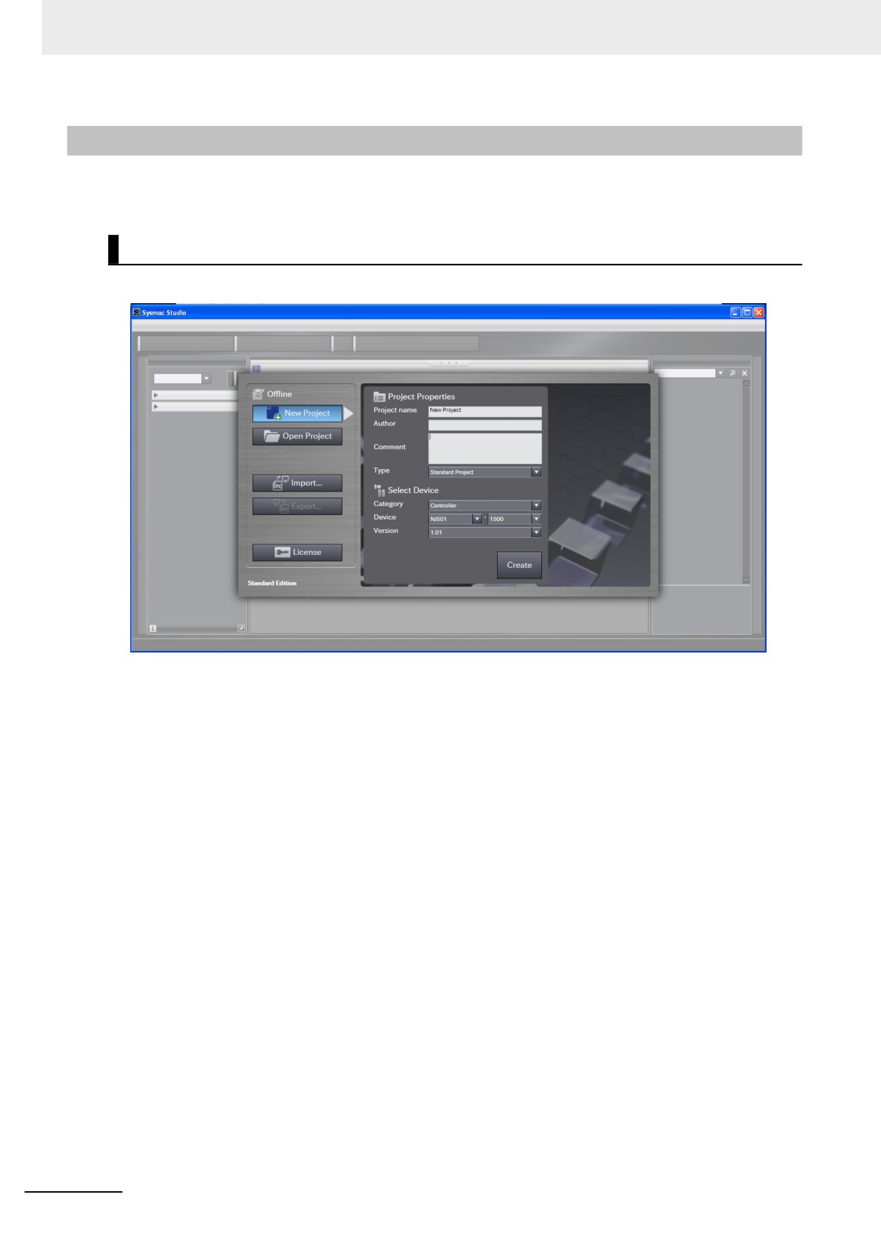
Start the Sysmac Studio.
Create a project in Sysmac Studio.
11-4
11 Example of Actual Application Procedures
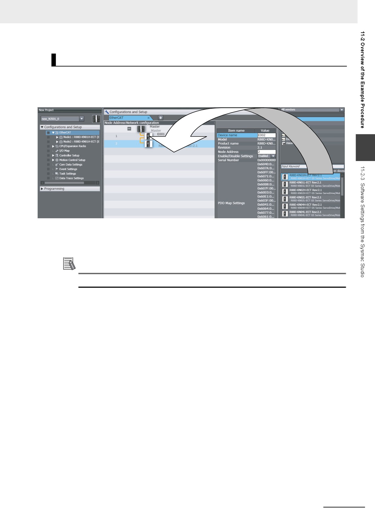
Create the EtherCAT Slave Configuration.
1 Double-click EtherCAT under Configurations and Setup.
2 Create the slave configuration by dragging slaves.
11
3 Select the master and set the master parameters.
4 Select each slave and set the slave parameters.
Additional Information
At this point, you can use forced resetting from the I/O Map to check the wiring.
11-5
11 Example of Actual Application Procedures
Register the Global Variables and Device Variables.
z Registering Global Variables
1 Double-click Global Variables under Programming − Data.
2 Register the global variables in the global variable table.
z Registering Device Variables
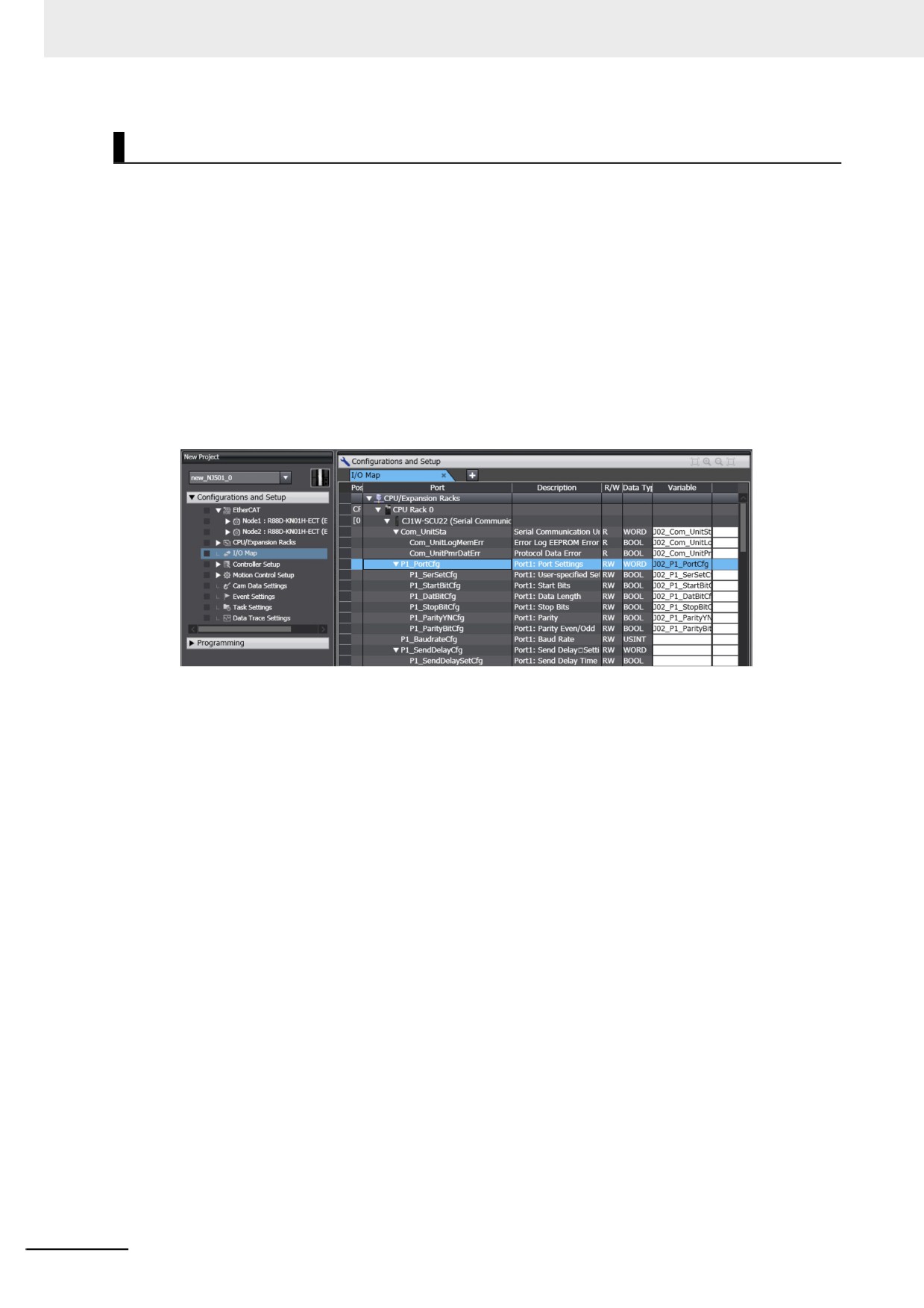
1 Double-click I/O Map under Configurations and Setup.
2 In the I/O Map, assign the variables to the I/O ports. (The I/O ports are created automatically
from the slave configurations.)
You can automatically create device variable names with the Sysmac Studio. To do so, right-
click an I/O port and select Create Device Variable from the menu.
By default, device variables are registered in the global variable table. If necessary, you can
change the variable type from a global variable to a local variable (internal variable) for a POU.
11-6
11 Example of Actual Application Procedures
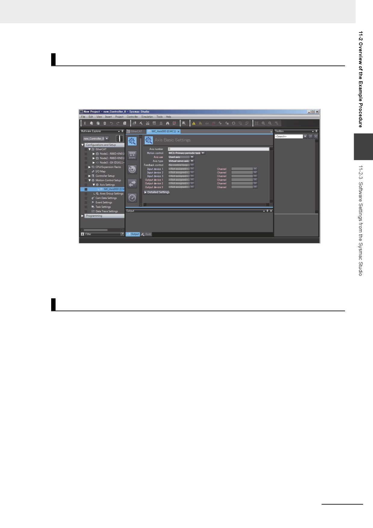
Create Axes (Axis Variables)
1 Right-click Axis Settings under Configurations and Setups − Motion Control Setup and
select Add − Axis Settings from the menu.
2 Assign Servo Drives to the axes (axis variables) that you created in the EtherCAT configuration.
11
• Set the Axis Use parameter to Used Axis.
• Set the Axis Type parameter to Servo Axis.
• Set the Input Device and Output Device parameters to the EtherCAT slaves that you regis-
tered in the slave configuration.
Set the other parameters, such as the Unit Conversion Settings and Operation Settings.
Set the Controller Setup.
z Initial Settings for the PLC Function Module:
The Controller Setup includes the Startup Mode and other parameters.
11-7
11 Example of Actual Application Procedures
11-2-4
Programming with the Sysmac Studio
On the Sysmac Studio, create the programs, set the tasks, and build the project.
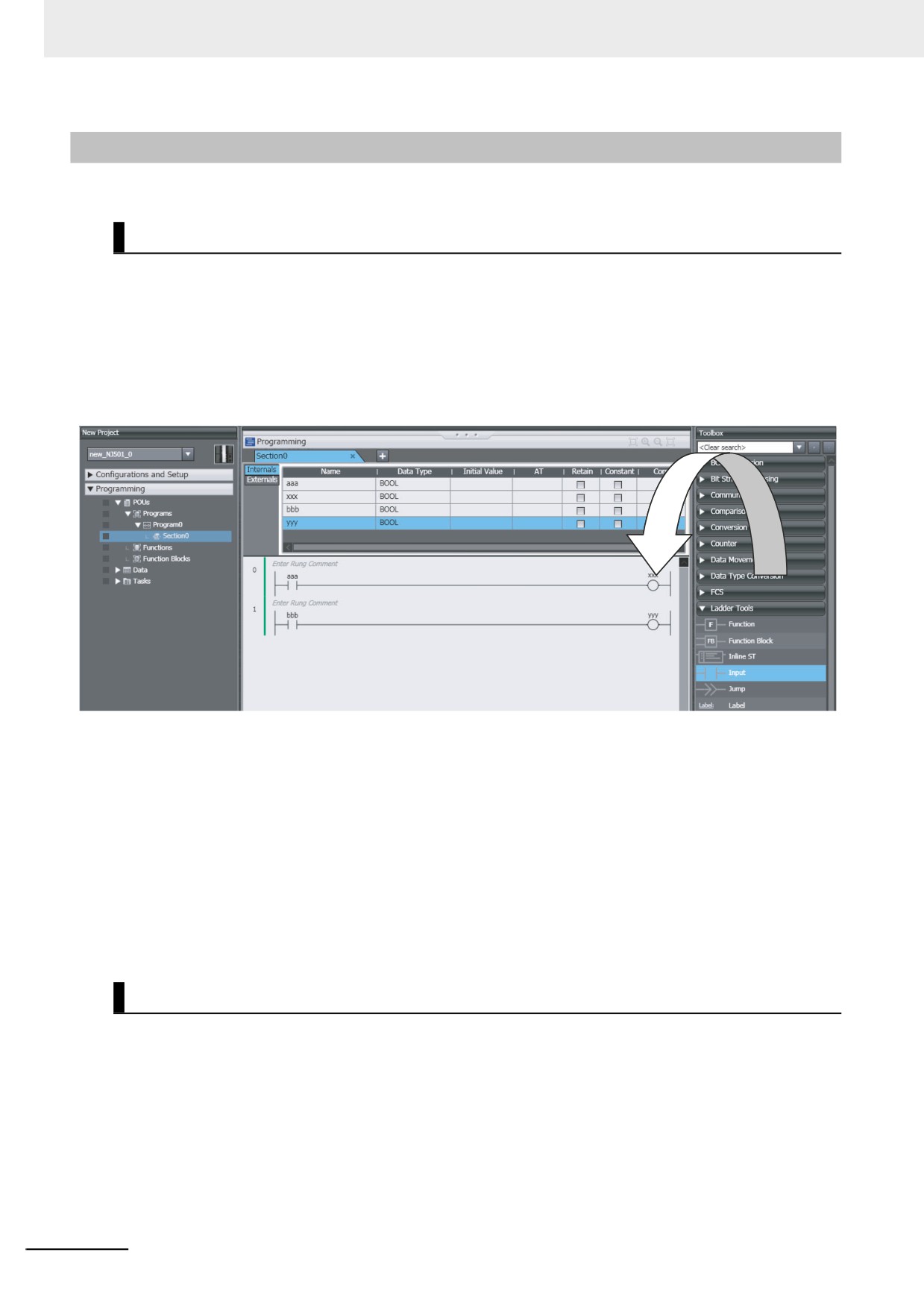
Write the Programs.
1 Right-click Programs under Programming − POU and select Add − Ladder or Add − ST from
the menu.
2 Double-click Section under the program that you registered.
3 Register the local variables for each program.
4 Enter the programs.
Create a program with the following instructions.
• Homing: MC_Home instruction
• Velocity control: MC_MoveVelocity instruction
• Interrupt feeding: MC_MoveFeed instruction
• Positioning: MC_Move instruction
5 As required, right-click Functions or Function Blocks under Programming − POU and select
Add − Ladder or Add − ST from the menu.
Double-click the function or function block that you registered. Register local variables for each
function and function block. Create the algorithms.
Note For a ladder diagram, press the R Key and create the following rungs.
Set Up the Tasks.
Double-click Task Settings under Configurations and Setup.
• In the Task Settings, set the task period and execution condition for the primary periodic task from
the pulldown list.
• In the I/O Control Task Settings, select the task name to which to assign each Unit and slave.
• In the Program Assignment Settings, assign the programs to the primary periodic task or the prior-
ity-16 periodic task.
11-8

11 Example of Actual Application Procedures
Build the Project.
Select Build from the Project Menu.
11-2-5
Checking Operation and Starting Operation on the Actual System
Go online with the Controller, download the project, check the wiring and perform test operation before
you start actual operation.
Going Online
11
1 Turn ON the power supply to NY-series Controller.
2 Connect the computer and the NY-series Controller with EtherNet/IP.
3 Select Communications Setup from the Controller Menu. Select the connection method for the
connection configuration in the Connection Type Field.
4 Select Online from the Controller Menu.
Downloading the Project with the Synchronize Menu
Select Synchronize from the Controller Menu and download the project to the Controller.
Note Use the Synchronize Menu of the Sysmac Studio to upload and download the project.
Checking Wiring
Check the wiring by performing forced-refreshing with user-specified values from the I/O Map or Ladder
Editor.
11-9
11 Example of Actual Application Procedures
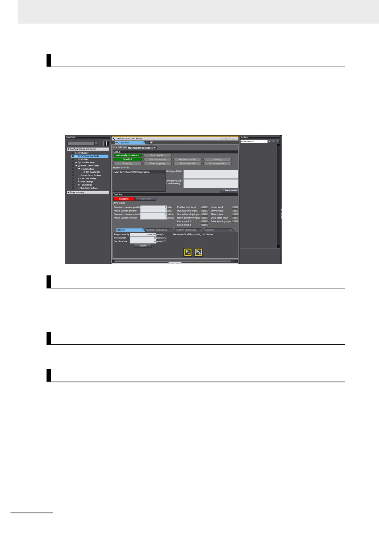
MC Test Run
1 Open the MC Test Run Tab Page.
2 Change the NY-series Controller to PROGRAM mode.
3 Monitor input signals on the display to check the wiring.
4 Jog the axis from the display.
Manual Operation
Change the NY-series Controller to RUN mode.
• Turning the Servo ON and OFF: Execute the MC_Power motion control instruction.
• Jogging: Execute the MC_MoveJog motion control instruction.
Homing
Homing: Execute the MC_Home instruction.
Actual Operation
Select Operation Mode − RUN Mode from the Controller Menu. If an error occurs, investigate the
cause and edit the user program.
11-10
Appendices
A
The appendices provide the NY-series Controller specifications, real processing times
of tasks, system-defined variable lists, and other supplemental information for the body
of this manual.
A-1
Specifications
A-3
A-1-1
Performance Specifications
A-3
A-1-2
Function Specifications
A-6
A-2
Calculating Guidelines for the Real Processing Times of
Tasks for the NY-series System
A-13
A-2-1
Calculating the Average Real Processing Times of Tasks
A-14
A-2-2
Example of Calculating the Average Real Processing Time of a
Task and Setting the Task Period
A-20
A-3
System-defined Variables
A-23
A-3-1
System-defined Variables for the Overall NY-series Controller
(No Category)
A-24
A-3-2
PLC Function Module, Category Name: _PLC
A-32
A-3-3
Motion Control Function Module, Category Name: _MC
A-33
A-3-4
EtherCAT Master Function Module, Category Name: _EC
A-35
A-3-5
EtherNet/IP Function Module, Category Name: _EIP
A-40
A-3-6
Meanings of Error Status Bits
A-51
A-4
Specifications for Individual System-defined Variables
A-52
A-4-1
System-defined Variables for the Overall NY-series Controller
(No Category)
A-53
A-4-2
PLC Function Module, Category Name: _PLC
A-66
A-4-3
Motion Control Function Module, Category Name: _MC
A-68
A-4-4
EtherCAT Master Function Module, Category Name: _EC
A-70
A-4-5
EtherNet/IP Function Module, Category Name: _EIP
A-79
A-5
Attributes of Controller Data
A-91
A-6
Variable Memory Allocation Methods
A-94
A-6-1
Variable Memory Allocation Rules
A-94
A-6-2
Important Case Examples
A-103
A-7
Registering a Symbol Table on the CX-Designer
A-106
A-8
Enable/Disable EtherCAT Slaves and Axes
A-109
A-8-1
Project Settings When Using EtherCAT Slaves and Axes
A-109
A-1
Appendices
A-8-2
Using Instructions to Enable/Disable EtherCAT Slaves and Axes
A-109
A-8-3
System-defined Variables That Indicate EtherCAT Slave or Axis Status . . . A-110
A-8-4
Enabling/Disabling Execution of Program
A-110
A-8-5
Checking Enabled/Disabled Program
A-111
A-8-6
Settings with the Sysmac Studio
A-111
A-8-7
Examples of Applications of Enabling/Disabling EtherCAT Slaves
and Axes
A-112
A-9 Size Restrictions for the User Program
A-115
A-9-1
User Program Object Restrictions
A-115
A-9-2
Counting User Program Objects
A-117
A-10 Version Information for NY-series Controllers
A-119
A-10-1
Relationship between Unit Versions of Controllers and Sysmac
Studio Versions
A-119
A-10-2
Functions That Were Added or Changed for Each Unit Version
A-120
A-2
Appendices
A-1
Specifications
This section gives the functional and performance specifications of the control function of the NY-series
Industrial Panel PC / Industrial Box PC with Machine Automation Control Software.
Refer to the NY-series Industrial Panel PC Hardware User’s Manual (Cat. No. W557) or the NY-series
Industrial Box PC Hardware User’s Manual (Cat. No. W556) for the general specifications.
A-1-1
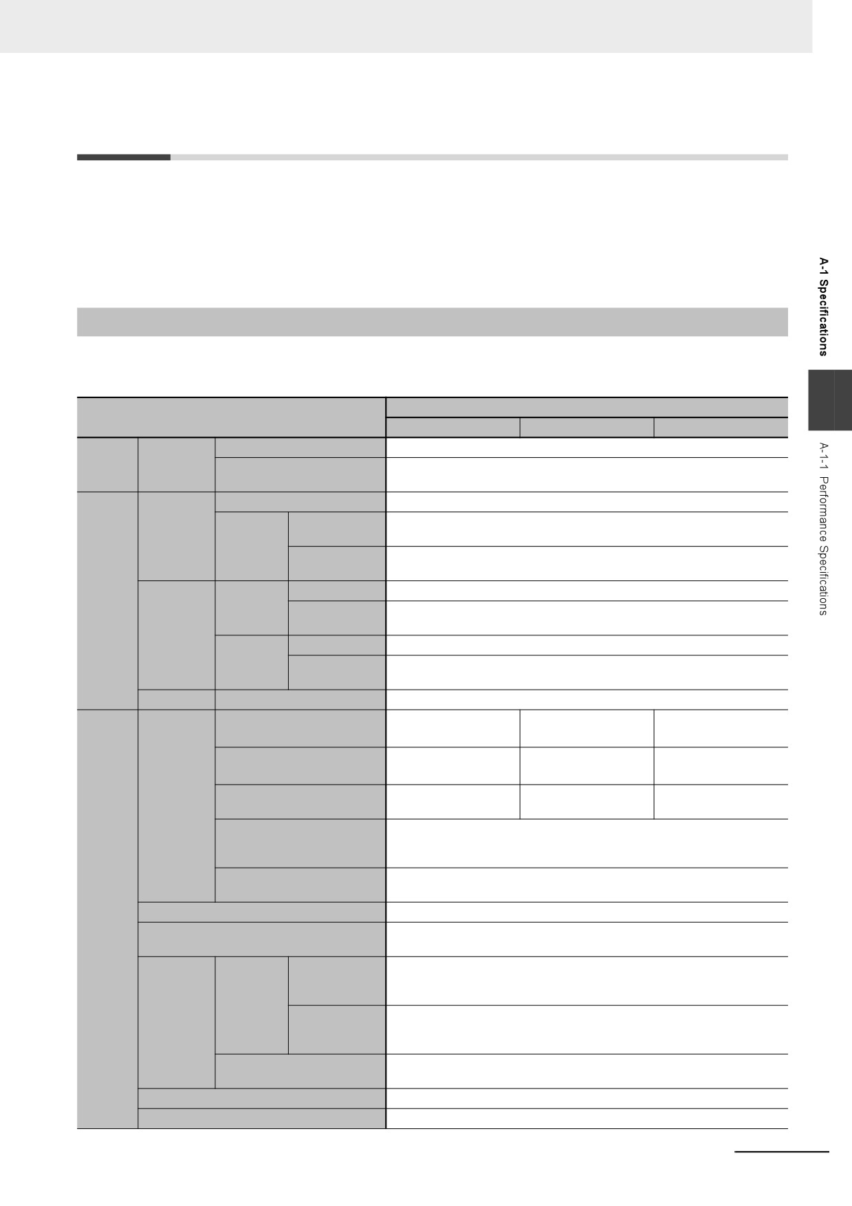
Performance Specifications
This section gives the performance specifications of the control function of the NY-series Industrial
Panel PC / Industrial Box PC.
A
Item
NY52-
15
4
13
Instruction
LD instruction
0.33 ns or more
Process-
execution
Math instructions (for long
1.2 ns or more
ing time
times
real data)
Size
40 MB
Number of POU
3,000
Program
definitions
capacity*1
Quantity
Number of POU
24,000
instances
Pro-
Size
4 MB
gram-
Retain attri-
Number of vari-
40,000
ming
butes
Memory
ables
capacity for
Size
64 MB
variables
No Retain
Number of vari-
180,000
attributes
ables
Data types
Number of data types
4,000
Maximum number of con-
64 axes
32 axes
16 axes
trolled axes*2
Maximum number of used
64 axes
32 axes
16 axes
real axes*3
Number of
Maximum number of axes for
64 axes
32 axes
16 axes
controlled
single-axis control
axes
Maximum number of axes for
4 axes per axes group
linear interpolation axis con-
trol
Number of axes for circular
2 axes per axes group
interpolation axis control
Motion
Maximum number of axes groups
32 axes groups
control
The same control period as that is used for the process data communications
Motion control period
cycle for EtherCAT.
Maximum
65,535 points
points per cam
Number of
table
cam data
Maximum
1,048,560 points
Cams
points
points for all
cam tables
Maximum number of cam
640 tables
tables
Position units
Pulse, mm, μm, nm, degree, and inch
Override factors
0.00%, or 0.01% to 500.00%
A-3
Appendices
Item
NY52-
15
4
13
Number of ports
1
Physical layer
10BASE-T, 100BASE-TX, or 1000BASE-T
Frame length
1,514 bytes max.
Media access method
CSMA/CD
Modulation
Baseband
Topology
Star
Baud rate
1 Gbps (1000BASE-T)
Transmission media
STP (shielded, twisted-pair) cable of Ethernet category 5, 5e, or higher
Maximum transmission distance between
100 m
Ethernet switch and node
Maximum number of cascade connections
There are no limitations when an Ethernet switch is used.
Maximum number of connec-
128
tions
Can be set for each connection.
Packet interval*4
1 to 10,000 ms in 1-ms increments
Permissible communica-
20,000 pps*5 (including heartbeat)
tions band
Maximum number of tage
128
sets
CIP ser-
Tag types
Network variables
Built-in
vice: Tag
Ether-
data links
Number of tags per connec-
8 (7 tags if Controller status is included in the tag set.)
Net/IP
(cyclic com-
tion (i.e., per tag set)
port
munica-
Maximum number of tags
256
tions)
Maximum link data size per
184,832 bytes
node (total size for all tags)
Maximum data size per con-
1,444 bytes
nection
Maximum number of registra-
128 (1 connection = 1 tag set)
ble tag sets
Maximum tag set size
1,444 bytes (Two bytes are used if Controller status is included in the tag set.)
Multi-cast packet filter*6
Supported
Class 3 (number of connec-
64 (clients plus server)
tions)
Maximum num-
32
ber of clients
CIP mes-
that can com-
sage ser-
UCMM
municate at one
vice
(non-con-
time
: Explicit
messages
nection
Maximum num-
32
type)
ber of servers
that can com-
municate at one
time
Number of TCP sockets
30
A-4
Appendices
Item
NY52-
15
4
13
Communications standard
IEC 61158 Type12
EtherCAT master specifications
Class B (Feature Pack Motion Control compliant)
Physical layer
100BASE-TX
Modulation
Baseband
Baud rate
100 Mbps (100BASE-TX)
Duplex mode
Auto
Topology
Line, daisy chain, and branching
Twisted-pair cable of category 5 or higher (double-shielded straight cable with
Transmission media
aluminum tape and braiding)
Built-in
Maximum transmission distance between
100 m
Ether-
nodes
CAT port
Maximum number of slaves
128
Range of node addresses that can be set
1 to 512
A
Inputs: 5,736 bytes
Maximum process data size
Outputs: 5,736 bytes
However, the maximum number of process data frames is 4.
Inputs: 1,434 bytes
Maximum process data size per slave
Outputs: 1,434 bytes
Communications cycle
500, 1,000, 2,000, 4,000, or 8,000 μs
Sync jitter
1 μs max.
Maximum
4,096
number of
Maximum number of NX
Unit con-
(On EtherCAT Slave Terminals)
figura-
connect-
Units for entire controller
tion
able Units
Maximum number of Expansion Racks
0
At ambient temperature of 55°C: −3.5 to +0.5 minute error per month
Internal clock
At ambient temperature of 25°C: −1.5 to +1.5 minute error per month
At ambient temperature of 0°C: −3 to +1 minute error per month
*1
This is the capacity for the execution objects and variable tables (including variable names).
*2
This is the total for all axis types.
*3
This is the total number of axes that are set as servo axes or encoder axes and are also set as used axes.
*4
Data will be refreshed at the set interval, regardless of the number of nodes.
*5
“pps” means packets per second, i.e., the number of communications packets that can be sent or received in one second.
*6
As the EtherNet/IP port implements the IGMP client, unnecessary multi-cast packets can be filtered by using an Ethernet switch that
supports IGMP Snooping.
A-5
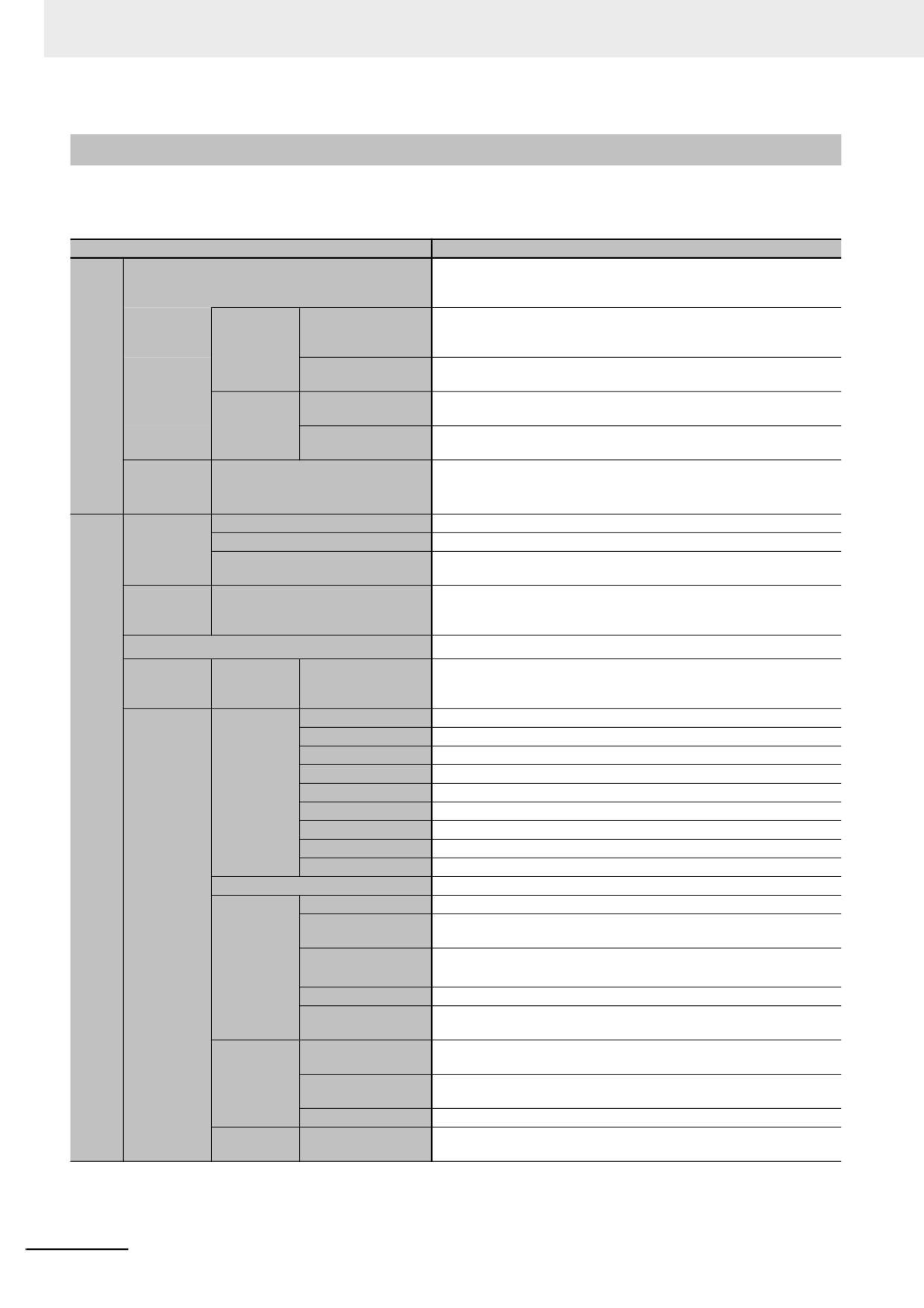
Appendices
A-1-2
Function Specifications
This section gives the functional specifications of the control function of the NY-series Industrial Panel
PC / Industrial Box PC.
Item
NY52-
I/O refresh and the user program are executed in units that are called
Function
tasks. Tasks are used to specify execution conditions and execution pri-
ority.
Maximum number of
1
Periodically
primary periodic
executed
tasks
tasks
Maximum number of
3
Tasks
periodic tasks
Maximum number of
32
Condition-
event tasks
ally exe-
Execution condi-
When Activate Event Task instruction is executed or when condition
cuted tasks
tions
expression for variable is met
---
System Service Monitoring Set-
Setup
tings
Programs
POUs that are assigned to tasks.
POUs (pro-
Function blocks
POUs that are used to create objects with specific conditions.
gram organi-
POUs that are used to create an object that determine unique outputs for
zation units)
Functions
the inputs, such as for data processing.
Program-
Ladder diagrams*1 and structured text (ST)
ming
Types
languages
Namespaces
Namespaces are used to create named groups of POU definitions.
External
The function which allows access from the HMI, host computers, or other
Variables
access of
Network variables
Controllers
variables
Boolean
BOOL
Bit strings
BYTE, WORD, DWORD, and LWORD
Integers
INT, SINT, DINT, LINT, UINT, USINT, UDINT, and ULINT
Real numbers
REAL and LREAL
Basic data
Durations
TIME
types
Dates
DATE
Pro-
Times of day
TIME_OF_DAY
gram-
Dates and times
DATE_AND_TIME
ming
Text strings
STRING
Derivative data types
Structures, Unions, and Enumerations
Function
A derivative data type that groups together data with different data types.
Maximum number of
2,048
Data types
members
Nesting maximum
8
Structures
levels
Member data types
Basic data types, structures, unions, enumerations, or array variables
Specifying member
You can use member offsets to place structure members at any memory
offsets
locations.
A derivative data type that enables access to the same data with different
Function
data types.
Union
Maximum number of
4
members
Member data types
BOOL, BYTE, WORD, DWORD, and LWORD
A derivative data type that uses text strings called enumerators to
Enumeration
Function
express variable values.
A-6
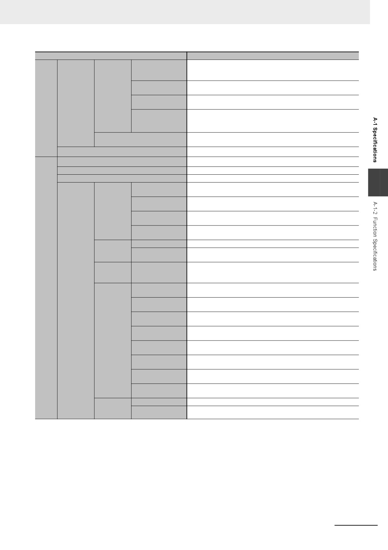
Appendices
Item
NY52-
An array is a group of elements with the same data type. You specify the
Function
number (subscript) of the element from the first element to specify the
element.
Maximum number of
3
dimensions
Array speci-
Data type
fications
Maximum number of
65,535
Pro-
attributes
elements
gram-
ming
Array specifica-
Supported
tions for FB
instances
You can specify a range for a data type in advance. The data type can
Range specifications
take only values that are in the specified range.
Libraries
You can use user libraries.
Control modes
Position control, Velocity control, and Torque control
Axis types
Servo axes, Virtual servo axes, Encoder axes, and Virtual encoder axes
Positions that can be managed
Command positions and actual positions
A
Absolute position-
Positioning is performed for a target position that is specified with an
ing
absolute value.
Positioning is performed for a specified travel distance from the com-
Single-axis
Relative positioning
mand current position.
position
Positioning is performed for a specified travel distance from the position
control
Interrupt feeding
where an interrupt input was received from an external input.
Cyclic synchronous
A positioning command is output each control period in Position Control
absolute positioning
Mode.
Single-axis
Velocity control
Velocity control is performed in Position Control Mode.
velocity con-
Cyclic synchronous
A velocity command is output each control period in Velocity Control
trol
velocity control
Mode.
Single-axis
The torque of the motor is controlled.
torque con-
Torque control
trol
Motion
con-
Starting cam opera-
A cam motion is performed using the specified cam table.
trol
tion
Single axes
Ending cam opera-
The cam motion for the axis that is specified with the input parameter is
tion
ended.
Starting gear opera-
A gear motion with the specified gear ratio is performed between a mas-
tion
ter axis and slave axis.
Positioning gear oper-
A gear motion with the specified gear ratio and sync position is per-
Single-axis
ation
formed between a master axis and slave axis.
synchro-
Ending gear opera-
The specified gear motion or positioning gear motion is ended.
nized control
tion
Synchronous position-
Positioning is performed in sync with a specified master axis.
ing
Master axis phase
The phase of a master axis in synchronized control is shifted.
shift
The command positions of two axes are added or subtracted and the
Combining axes
result is output as the command position.
Single-axis
Powering the Servo
The Servo in the Servo Drive is turned ON to enable axis motion.
manual
An axis is jogged at a specified target velocity.
Jogging
operation
A-7
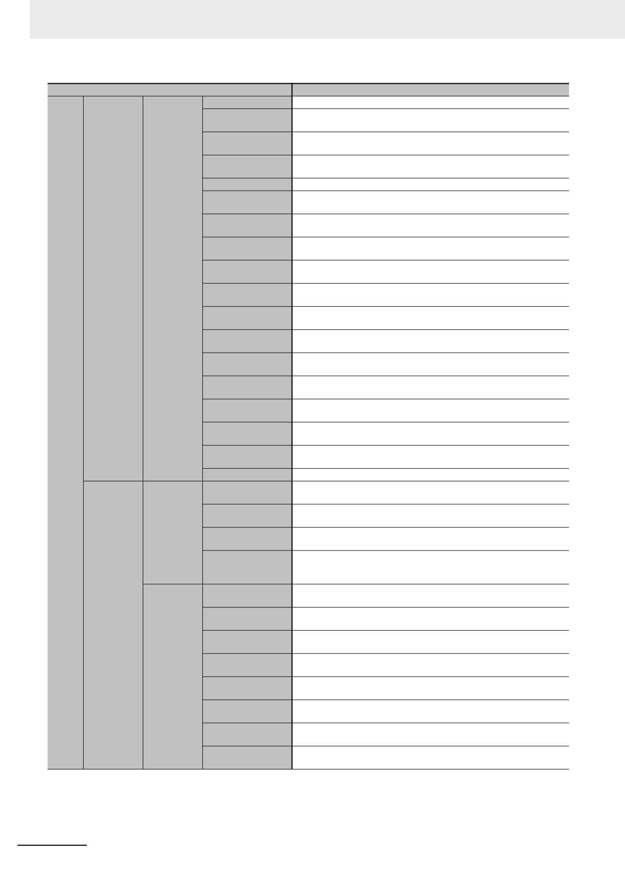
Appendices
Item
NY52-
Resetting axis errors
Axes errors are cleared.
A motor is operated and the limit signals, home proximity signal, and
Homing
home signal are used to define home.
Homing with speci-
The parameters are specified, the motor is operated, and the limit sig-
fied parameters
nals, home proximity signal, and home signal are used to define home.
Positioning is performed for an absolute target position of 0 to return to
High-speed homing
home.
Stopping
An axis is decelerated to a stop.
Immediately stop-
An axis is stopped immediately.
ping
Setting override fac-
The target velocity of an axis can be changed.
tors
Changing the cur-
The command current position or actual current position of an axis can
rent position
be changed to any position.
Enabling external
The position of an axis is recorded when a trigger occurs.
Auxiliary
latches
functions for
Single axes
Disabling external
The current latch is disabled.
single-axis
latches
control
You can monitor the command position or actual position of an axis to
Zone monitoring
see when it is within a specified range (zone).
Enabling digital cam
You can turn a digital output ON and OFF according to the position of an
switches
axis.
Monitoring axis fol-
You can monitor whether the difference between the command positions
lowing error
or actual positions of two specified axes exceeds a threshold value.
Resetting the fol-
The error between the command current position and actual current posi-
lowing error
tion is set to 0.
The torque control function of the Servo Drive can be enabled or dis-
Torque limit
abled and the torque limits can be set to control the output torque.
Motion
Command position
The function which compensate the position for the axis in operation.
con-
compensation
trol
Outputs the specified offset position for the slave axis in synchronous
Cam monitor(*)
control.
Start velocity
You can set the initial velocity when axis motion starts.
Absolute linear
Linear interpolation is performed to a specified absolute position.
interpolation
Relative linear inter-
Linear interpolation is performed to a specified relative position.
Multi-axes
polation
coordinated
Circular 2D interpo-
Circular interpolation is performed for two axes.
control
lation
Axes group cyclic
A positioning command is output each control period in Position Control
synchronous abso-
Mode.
lute positioning
Resetting axes
Axes group errors and axis errors are cleared.
group errors
Enabling axes
Motion of an axes group is enabled.
Axes groups
groups
Disabling axes
Motion of an axes group is disabled.
groups
Auxiliary
Stopping axes
All axes in interpolated motion are decelerated to a stop.
functions for
groups
multi-axes
Immediately stop-
All axes in interpolated motion are stopped immediately.
coordinated
ping axes groups
control
Setting axes group
The blended target velocity is changed during interpolated motion.
override factors
Reading axes group
The command current positions and actual current positions of an axes
positions
group can be read.
Changing the axes
The Composition Axes parameter in the axes group parameters can be
in an axes group
overwritten temporarily.
A-8
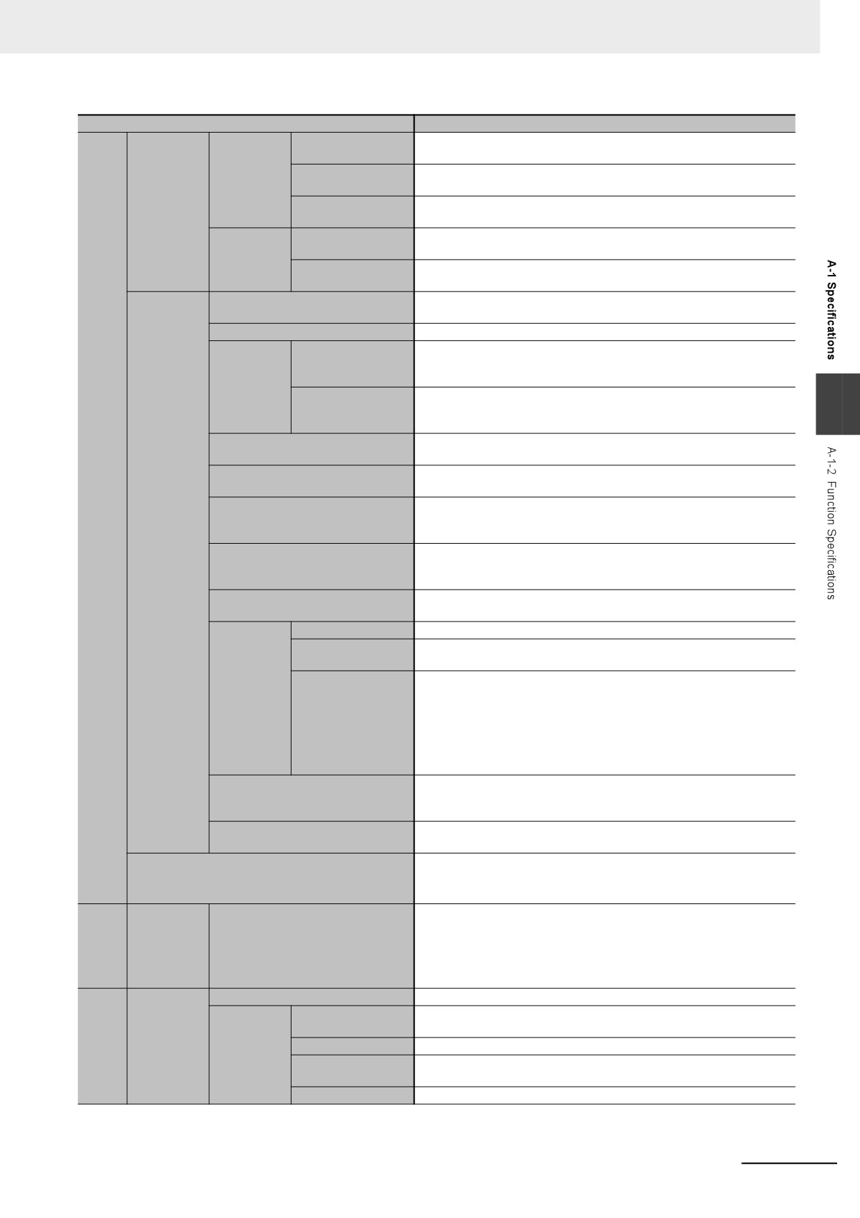
Appendices
Item
NY52-
Setting cam table
The end point index of the cam table that is specified in the input param-
properties
eter is changed.
The cam table that is specified with the input parameter is saved in non-
Cams
Saving cam tables
volatile memory in the CPU Unit.
Common
Generating cam
The cam table is generated from the cam property and cam node that is
items
tables
specified in input parameters.
Some of the axis parameters or axes group parameters are overwritten
Writing MC settings
temporarily.
Parameters
Changing axis
Some of the axis parameters can be accessed or changed from the user
parameters
program.
You can select either Linear Mode (finite length) or Rotary Mode (infinite
Count modes
length).
Unit conversions
You can set the display unit for each axis according to the machine.
Automatic accelera-
Jerk is set for the acceleration/deceleration curve for an axis motion or
tion/deceleration
axes group motion.
Accelera-
control
tion/deceler-
Changing the accel-
You can change the acceleration or deceleration rate even during accel-
ation control
A
eration and deceler-
eration or deceleration.
ation rates
You can set an in-position range and in-position check time to confirm
In-position check
when positioning is completed.
You can set the stop method to the immediate stop input signal or limit
Stop method
input signal.
Motion
You can change the input variables for a motion control instruction during
Re-execution of motion control
con-
execution and execute the instruction again to change the target values
instructions
trol
during operation.
You can specify when to start execution and how to connect the veloci-
Multi-execution of motion control
Auxiliary
ties between operations when another motion control instruction is exe-
instructions (Buffer Mode)
functions
cuted during operation.
Continuous axes group motions
You can specify the Transition Mode for multi-execution of instructions
(Transition Mode)
for axes group operation.
Software limits
The movement range of an axis is monitored.
The error between the command current value and the actual current
Following error
value is monitored for an axis.
Velocity, acceleration
You can set and monitor warning values for each axis and each axes
Monitoring
rate, deceleration rate,
group.
functions
torque, interpolation
velocity, interpolation
acceleration rate, and
interpolation decelera-
tion rate
You can use an OMRON 1S-series Servomotor or G5-series Servomotor
Absolute encoder support
with an Absolute Encoder to eliminate the need to perform homing at
startup.
You can inverse the logic of immediate stop input signal, positive limit
Input signal logic inversion
input signal, negative limit input signal, or home proximity input signal.
The Servo Drive input signals listed on the right are used.
External interface signals
Home signal, home proximity signal, positive limit signal, negative limit
signal, immediate stop signal, and interrupt input signal
128
Unit
(I/O)
EtherCAT
man-
Maximum number of slaves
slaves
age-
ment
Communications protocol
TCP/IP and UDP/IP
Classless inter-domain routing is the function used to allocate IP
CIDR
Commu-
addresses that do not use classes (Class A to C).
EtherNet/IP
nica-
TCP/IP func-
IP Forwarding
This function is used to transfer IP packets over multiple interfaces.
port
tions
tion
This function is used to determine passing or blocking IP packets based
Packet Filter*2
on source IP address and TCP port number.
NAT
This function is used to convert two IP addresses and transfer.
A-9
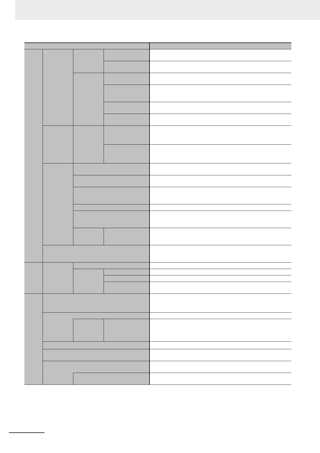
Appendices
Item
NY52-
Programless cyclic data exchange is performed with the devices on the
CIP commu-
Tag data links
EtherNet/IP network.
nications
Message communi-
CIP commands are sent to or received from the devices on the Ether-
services
cations
Net/IP network.
Data is sent to and received from any node on Ethernet using the UDP or
Socket services
TCP protocol. Socket communications instructions are used.
EtherNet/IP
Files are transferred via FTP from the CPU Unit to computers or Control-
port
FTP client
lers at other Ethernet nodes. FTP client communications instructions are
TCP/IP appli-
used.
cations
Files can be read from or written to the SD Memory Card in the CPU Unit
FTP server
from computers at other Ethernet nodes.
Built-in EtherNet/IP port internal status information is provided to network
SNMP agent
management software that uses an SNMP manager.
A communications method to exchange control information in cyclic com-
Process data com-
munications between the EtherCAT master and slaves.
munications
EtherCAT
Supported
This communications method is defined by CoE.
port
services
A communications method to exchange control information in noncyclic
Commu-
SDO communica-
event communications between EtherCAT master and slaves.
nica-
tions
tions
This communications method is defined by CoE.
Information is read from connected slave devices and the slave configu-
Network scanning
ration is automatically generated.
Time is synchronized by sharing the EtherCAT system time among all
DC (distributed clock)
EtherCAT devices (including the master).
The frames that are sent by the master and the frames that are received
Packet monitoring
by the master can be saved. The data that is saved can be viewed with
EtherCAT
WireShark or other applications.
port
Enable/disable settings for slaves
The slaves can be enabled or disabled as communications targets.
Temporarily disconnects a slave from the EtherCAT network for mainte-
Disconnecting/reconnecting slaves
nance, such as for replacement of the slave, and then connects the slave
again.
Support
SDO messages of the CAN application can be sent to slaves via Ether-
application
CoE
CAT
protocol
FTP client instructions, CIP communications instructions, socket commu-
Communications instructions
nications instructions, SDO message instructions, and Modbus RTU pro-
tocol instructions
Function
Events are recorded in the logs
Sys-
tem
System event log
2,048
Maximum
man-
Event logs
Access event log
1,024
number of
age-
User-defined event
1,024
events
ment
log
Programs, function blocks, functions, and global variables can be
Online editing
changed online.
More than one operators can change POUs individually via network.
Forced refreshing
The user can force specific variables to TRUE or FALSE.
Maximum
64
number of
Device variables for
forced vari-
EtherCAT slaves
Debug
ables
ging
MC Test Run
Motor operation and wiring can be checked from the Sysmac Studio.
The project file in the Sysmac Studio and the data in the CPU Unit can be
Synchronizing
made the same when online.
You can monitor when a variable changes to TRUE or changes to
Differential monitoring
FALSE.
Maximum number of monitored
8
variables
A-10
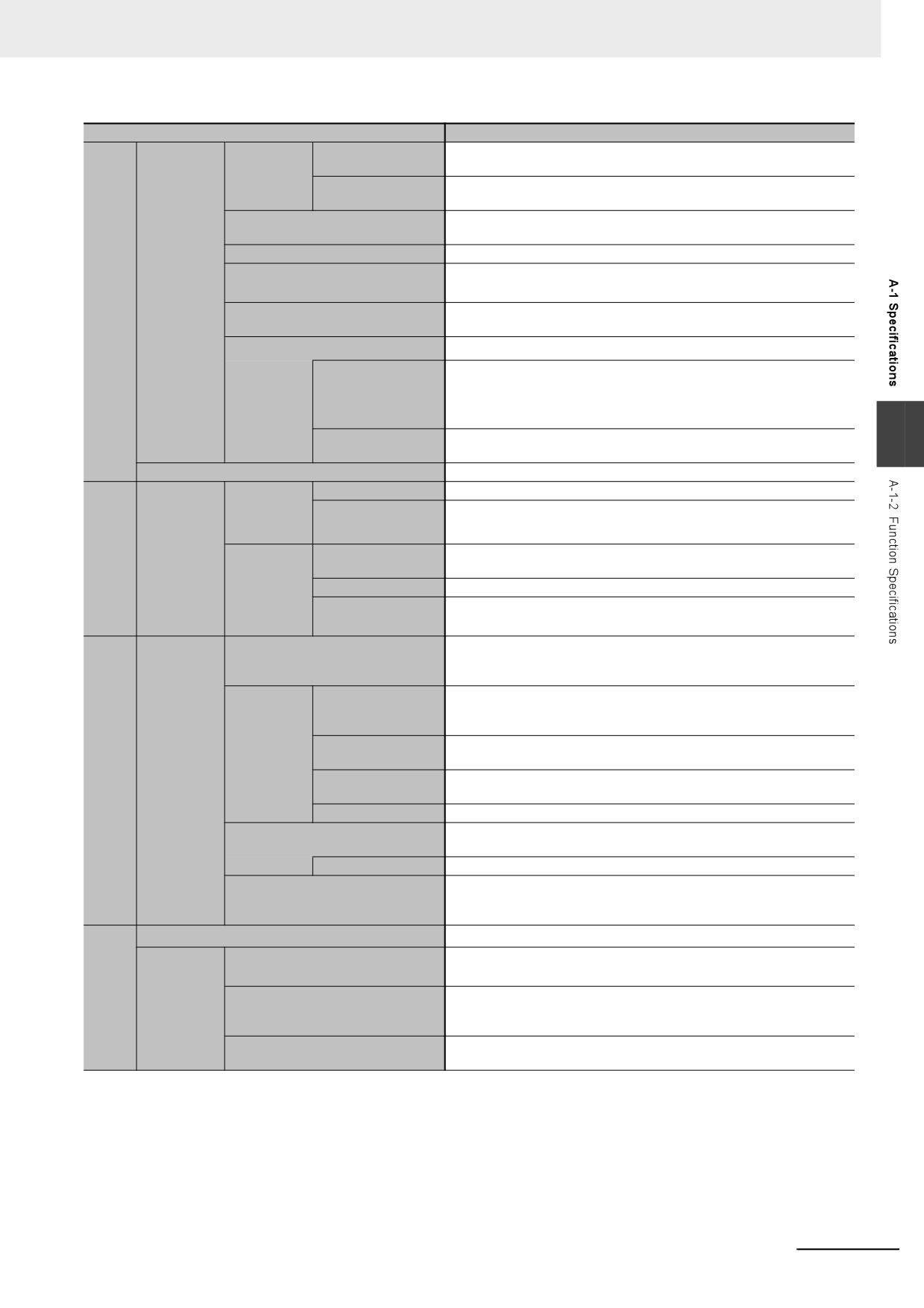
Appendices
Item
NY52-
Single triggered
When the trigger condition is met, the specified number of samples are
trace
taken and then tracing stops automatically.
Types
Data tracing is executed continuously and the trace data is collected by
Continuous trace
the Sysmac Studio.
Maximum number of simultaneous
4
data traces
Maximum number of records
10,000
Maximum number of sampled vari-
192 variables
ables
Debug
Data tracing
Sampling is performed for the specified task period, at the specified time,
ging
Timing of sampling
or when a sampling instruction is executed.
Triggered traces
Trigger conditions are set to record data before and after an event.
• When BOOL variable changes to TRUE or FALSE
• Comparison of non-BOOL variable with a constant
Trigger conditions
Comparison Method: Equals (=), Greater than (>), Greater than or
equals (≥), Less Than (<), Less than or equals (≤), Not equal (≠)
Trigger position setting: A slider is used to set the percentage of sam-
A
Delay
pling before and after the trigger condition is met.
Simulation
The operation of the CPU Unit is emulated in the Sysmac Studio.
Levels
Major faults, partial faults, minor faults, observation, and information
Controller
9 (Sysmac Studio)
Maximum number of
errors
message languages
2 (NS-series PT)
Reli-
ability
Self-diagno-
User-defined errors are registered in advance and then records are cre-
Function
func-
sis
ated by executing instructions.
tions
User-defined
Levels
8
errors
Maximum number of
9
message languages
When going online to a CPU Unit from the Sysmac Studio, the CPU Unit
CPU Unit names and serial IDs
name in the project is compared to the name of the CPU Unit being con-
nected to.
User program trans-
You can prevent reading data in the CPU Unit from the Sysmac Studio.
fer with no resto-
ration information
Protecting
CPU Unit write-pro-
You can prevent writing data to the CPU Unit from the Sysmac Studio or
software
Protection
tection
SD Memory Card.
Secu-
assets and
Overall Project file
You can use passwords to protect .smc files from unauthorized opening
rity
preventing
protection
on the Sysmac Studio.
operating
Data protection
You can use passwords to protect POUs on the Sysmac Studio.
mistakes
Online operations can be restricted by operation rights to prevent dam-
Verification of operation authority
age to equipment or injuries that may be caused by operating mistakes.
Number of groups
5
The user program cannot be executed without entering a user program
Verification of user program execu-
execution ID from the Sysmac Studio for the specific hardware (CPU
tion ID
Unit).
Save location
Shared folder*3
SD
SD Memory Card operation instruc-
You can access Virtual SD Memory Cards from instructions in the user
Mem-
tions
program.
ory
You can perform file operations for Controller files in the Virtual SD Mem-
Card
File operations from the Sysmac
Application
ory Card and read/write general-purpose document files on the com-
func-
Studio
puter.
tions
File operations by the FTP client
You can save and read files by the FTP client and server functions.
and sever functions
A-11

Appendices
Item
NY52-
Specification with
Backup and verification operations are performed by manipulating sys-
system-defined vari-
tem-defined variables.
ables
Operating
SD Memory
SD Memory Card
Backup and verification operations are performed from the SD Memory
Back-
methods
Card back-
Window in Sysmac
Card Window of the Sysmac Studio.
ing up
ups
Studio
data
Special instruction
The special instruction is used to backup data.
Disabling backups
Backing up data to a Virtual SD Memory Card is prohibited.
Protection
to SD Memory Cards
Sysmac Studio Controller backups
The Sysmac Studio is used to backup, restore, or verify Controller data.
*1
Inline ST is supported. (Inline ST is ST that is written as an element in a ladder diagram.)
*2
The function is available only for the internal port.
*3
The folder exists in HDD or SSD on which the Windows operates. The folder on the Controller is used as the Virtual SD Memory Card.
Note Items that are marked with asterisks in the table were added for version upgrades. Refer to A-10 Version Information for
NY-series Controllers for information on version upgrades.
A-12
Appendices
A-2
Calculating Guidelines for the Real
Processing Times of Tasks for the
NY-series System
This section describes how to calculate guidelines for the average real processing times of tasks on
paper for the NY-series System.
You must use the physical Controller to check the real processing times of tasks and task execution
times. For details, refer to 5-9 Task Design Methods and I/O Response Times.
A
Precautions for Correct Use
The task execution times in the physical Controller depends on the logic operations that are per-
formed in the user program, the presence of communications commands and data links, on
whether data tracing is performed, the load on Windows, the connection of Industrial Monitors,
the usage of PCIe cards, and on other factors.
Before starting actual operation, you must test performance under all foreseeable conditions on
the actual system and make sure that the task periods are not exceeded and that suitable com-
munications performance is achieved.
Additional Information
Periodic tasks is interrupted for the execution of tasks with higher execution priorities. The real
processing time of a task does not include the time for which the task is interrupted. It is the task
execution time that gives the actual time from when the task is started until it is finished, includ-
ing the interrupted time. For a detailed description of the differences between the real processing
times of tasks and the task execution times, refer to Meaning of the Task Execution Time and the
Real Processing Time of the Task on page 5-58.
A-13

Appendices
A-2-1
Calculating the Average Real Processing Times of Tasks
The average real processing time of a task is the total of the I/O refresh processing time, user program
execution time, motion control processing time and common processing time.
Average real processing time of task = I/O refresh processing time + User program execution time
+ Motion control processing time + Common processing time
The following processing is performed.
Priority-17
Primary
Priority-16
and
Processing
Processing contents
periodic task
periodic task
priority-18
periodic tasks
I/O refresh processing
I/O is refreshed for Eth-
Performed.
Not performed.
Not performed.
erCAT slaves.
User program execu-
• Programs assigned
Performed.
Performed.
Performed.
tion
to tasks are executed
in the order that they
are assigned.
Motion control process-
• Motion control com-
Performed.
Not performed.
Not performed.
ing
mands from the user
program are exe-
cuted.
• Motion output pro-
cessing
Com-
System
• Variable refresh pro-
Performed.
Performed.
Performed.
mon pro-
common
cessing (if there are
cessing
processing
accessing tasks) is
time
1
performed.
• Motion input process-
ing
• Data trace process-
ing
System
• Variable refresh pro-
Performed.
Performed.
Performed.
common
cessing (if there are
processing
refreshing tasks) is
2
performed.
• Variable access pro-
cessing external to
the Controller to
ensure concurrency
with task execution
System
Other system common
Performed.
Performed.
Performed.
overhead
processing
time
Guidelines are provided below for calculating the various processing times.
A-14
Appendices
I/O Refresh Processing Time
Use the following formula for the I/O refresh processing time.
I/O refresh processing time = EtherCAT slave processing time
The following describes how to determine the EtherCAT slave processing time.
Additional Information
The EtherCAT slave processing time is 0 in tasks to which EtherCAT slaves are not assigned.
A
z EtherCAT Slave Processing Time in Primary Periodic Task
Use the following formula to calculate the EtherCAT slave processing time in the primary periodic
task.
EtherCAT slave processing time [μs] = 0.0008 × pDout + 0.0028 × pDin + 0.082 × pDinout
+ (1.24 × Snum + 0.01 × Clen)
pDout
: Total output processing data size [byte] of EtherCAT slaves assigned to the primary
periodic task
pDin
: Total input processing data size [byte] of EtherCAT slaves assigned to the primary
periodic task
pDinout
: Total of the larger of the input and output processing data size of each EtherCAT
slave assigned to the primary periodic task [byte]
Snum
: Total number of EtherCAT slaves connected to the built-in EtherCAT port
Clen
: Total length of cables connected to the built-in EtherCAT port [m]
A-15
Appendices
User Program Execution Time
The user program execution time depends on the specific instructions multiplied by the numbers of
instructions used.
As a guideline, instructions are divided into three groups and the number of instructions in each group
is used for measurements and estimates.
• Standard instructions
• Arithmetic instructions for LREAL data
• Trigonometric instructions for LREAL data
Different instructions are used in a ladder diagram and in ST. Refer to Instruction Configuration for
Standard Ladder Diagram Instructions on page A-16 and Instruction Configuration for Standard ST
Instructions on page A-18 for information on the instruction configuration.
z
Simple Estimate
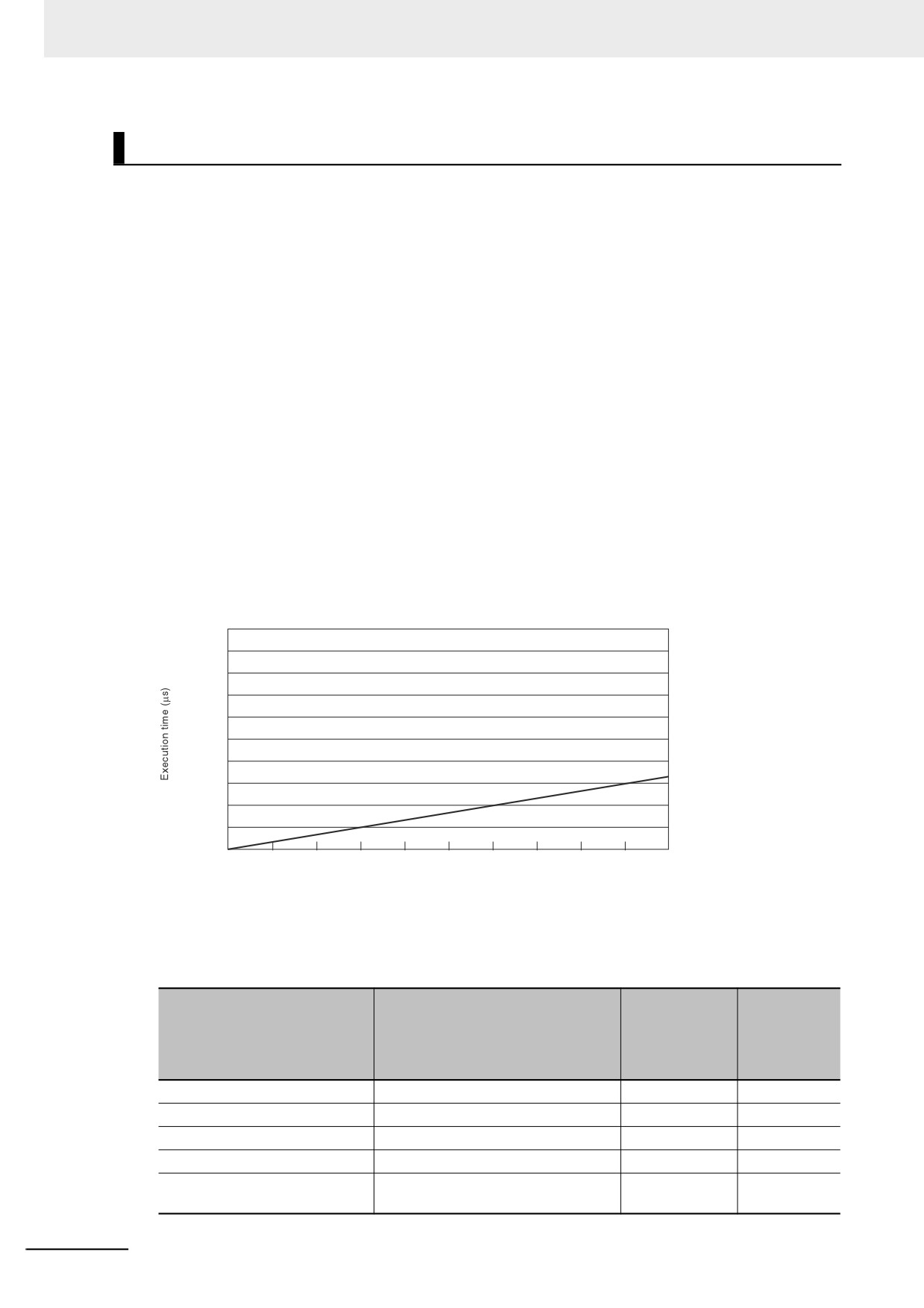
For the number of instructions in each group, read the execution time for each instruction group
from the following graphs and calculate the total.
• Execution time for standard instructions
• Execution time for arithmetic instructions for LREAL data
• Execution time for trigonometric instructions for LREAL data
This will allow you to estimate the execution time of the user program.
Execution Time for Standard Ladder Diagram Instructions
1000
900
800
700
600
500
400
300
200
NY5
2-
100
0
0
10000
20000
30000
40000
50000
60000
70000
80000
90000
100000
Total number of instructions
• Instruction Configuration for Standard Ladder Diagram Instructions
The instruction execution ratio for this configuration is 20%.
Percent of
Percent of
execution
Types of instructions
Instructions
instructions
time in
[%]
instruction
group [%]
Ladder diagram instructions
LD, AND, OUT, SET, and RESET
81.0%
40.2%
Comparison instructions
EQ and LT
4.1%
8.3%
Timer and counter instructions
Timer, TON/TOF, and CTU/CTD
1.6%
7.3%
Math instructions
+, -, *, /, ADD, SUB, MUL, and DIV
2.4%
6.5%
BCD conversion instructions and
INT_TO_DINT and WORD_BC-
0.2%
1.2%
data conversion instructions
D_TO_UINT
A-16