Omron IPC Machine Controller Industrial Panel PC / Industrial Box PC. Software User’s Manual (Industrial PC Platform NY-series) - page 14
8 Controller Functions
Clearing Event Logs
z Clearing Event Logs from the Sysmac Studio or an HMI
You can clear the event logs from the Sysmac Studio or from an HMI. You can clear the Controller
event log and user-defined event log separately.
Precautions for Correct Use
• If you need to delete event log in the Controller from the Sysmac Studio or an HMI, make sure
you do not need any of the event information before you delete the event log. You may have
overlooked some important information and observation level Controller events or user-
defined events. Always check for these before you delete an event log.
• Refer to the NY-series Troubleshooting Manual (Cat. No. W564) for restrictions on clearing an
event log from the PT.
z Clearing Event Logs with the Clear All Memory Operation
When you perform the Clear All Memory operation for an NY-series Controller from the Sysmac Stu-
dio, you can select whether to clear the event logs.
Exporting Event Logs
You can use the Sysmac Studio or an HMI to export the displayed event log to a CSV file.
8-54
8 Controller Functions
8-5-3
Controller Events (Controller Errors and Information)
Introduction
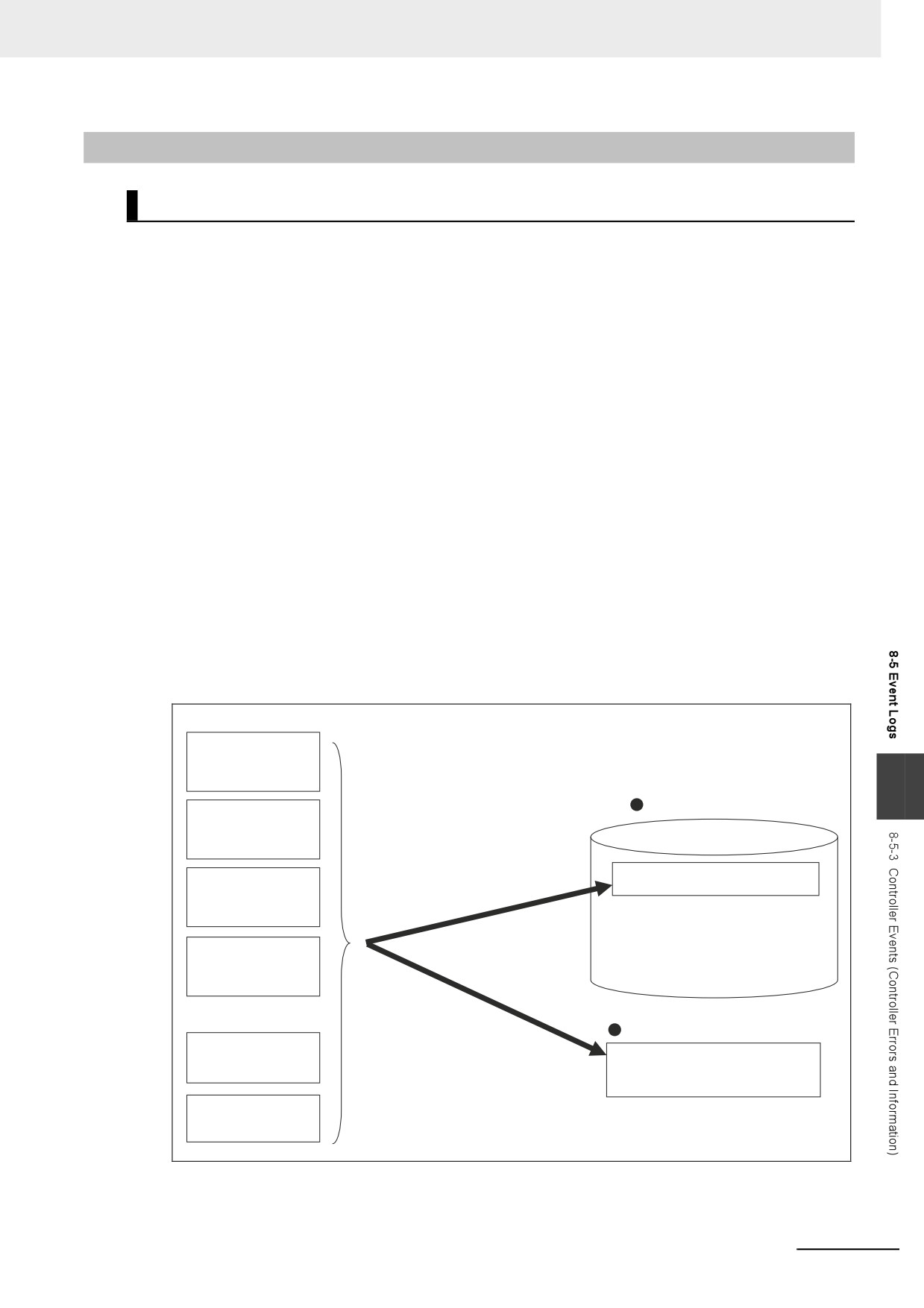
Controller errors and information are defined by the NY-series System.
These events occur when the NY-series System detects an error or information factor.
z
Controller Errors
These are system-defined errors.
“Controller error” is a collective term for major fault level, partial fault level, minor fault level, and
observation level Controller events.
Errors in the function modules of the NY-series Controller and EtherCAT slaves are detected. When
one of these events occurs, a Controller error is recorded in the event log.
To check the status of a Controller error on the user program, you execute the Get Error Status
instruction to access the status of the Error Status variable, which is a system-defined variable.
Controller errors are not reset when the operating mode changes.
Refer to the NY-series Troubleshooting Manual (Cat. No. W564) for details on Controller errors.
z
Controller Information
Controller information is system-defined notification information. This information does not indicate
errors. It represents information level Controller events. Examples include events other than errors,
such as turning the power ON and OFF, starting and stopping operation, connecting the Sysmac
Studio online, and downloading user programs.
Function Modules
PLC Function
Module
8
Event logs
Motion Control
Function Module
An error or information occurs.
EtherCAT
Controller events
Master Function
Module
EtherNet/IP
Function Module
System-defined variables
Errors in Special
Error status
Units
Detected Controller errors
Errors in EtherCAT
slaves
8-55
8 Controller Functions
8-5-4
User-defined Events (User-defined Errors and Information)
Introduction
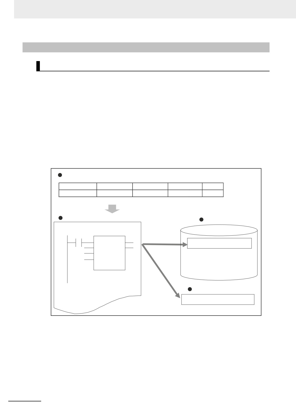
These errors and information are defined by the user. You can use instructions to create them.
z User-defined Errors
These errors are defined by the user. Use the Create User-defined Error (SetAlarm) instruction to
create user-defined errors. When this instruction is executed, a user-defined error is recorded in the
event log.
The corresponding system-defined variable changes to TRUE. User-defined errors are not reset
when the operating mode changes.
z User-defined Information
User-defined information is user-defined notification information. This information does not indicate
errors. Use the Create User-defined Information (SetInfo) instruction to create user-defined informa-
tion. When this instruction is executed, user-defined information is recorded in the event log.
Event Setting Tables
Event code
Event name
Level
Group
Details
100
Failure X
User fault level 1
Control A (001)
Instruction
Event logs
Program
SetAlarm
An event occurs.
User-defined events
System-defined Variables
User-defined error status
8-56
8 Controller Functions
Application Procedures
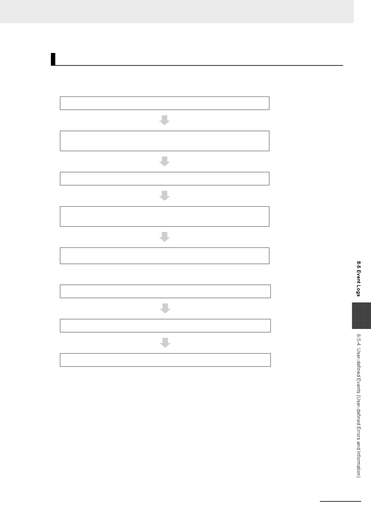
Use the following procedures.
z User-defined Errors
1. Register a user-defined error in the Event Setting Table.
2. Execute the Create User-defined Error (SetAlarm) instruction.
(Specify an event code that is defined in the Event Setting Table.)
3. A user-defined error occurs.
4. The corresponding system-defined variable _AlarmFlag (User-defined Error
Status) changes to TRUE. Execute any process for that condition.
5. Check the user-defined error in the event log with the Sysmac Studio, an
instruction, or an HMI.
z User-defined information
1. Register user-defined information in the Event Setting Table.
8
2. Execute the Create User-defined Information (SetInfo) instruction.
3. Check the record in the event log.
8-57
8 Controller Functions
Setting the Event Setting Table
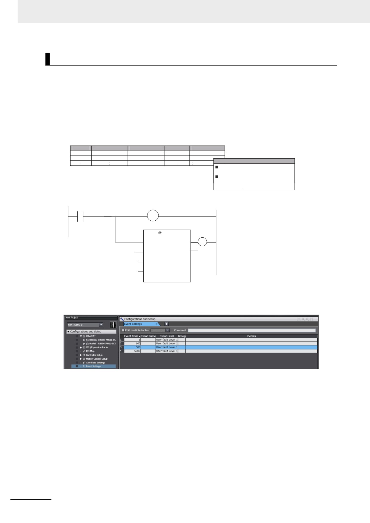
To create a user-defined error or user-defined information, register the user-defined error or user-
defined information in the Event Setting Table in the Sysmac Studio in advance.
The user events that you set here can be displayed on the Sysmac Studio or an HMI with the same
information.
You can register up to 5,120 events in the Event Setting Table.
Event Setting Table
Event Setting Table
Event code
Event name
Level
Group
Details
10001
Failure X
User fault Level3
Control A (001)
Details
Description
Failure X occurred.
Correction
Perform safety checks and handle the problem
according to the cause code.
Programming Example
Detection condition
Failure
SetAlarm
Normal end
EN
ENO
OutVal
UINT#102
Code
Var1
Info1
Var2
Info2
The following items are set in the Event Setting Table.
8-58
8 Controller Functions
z
Contents of the Event Setting Table
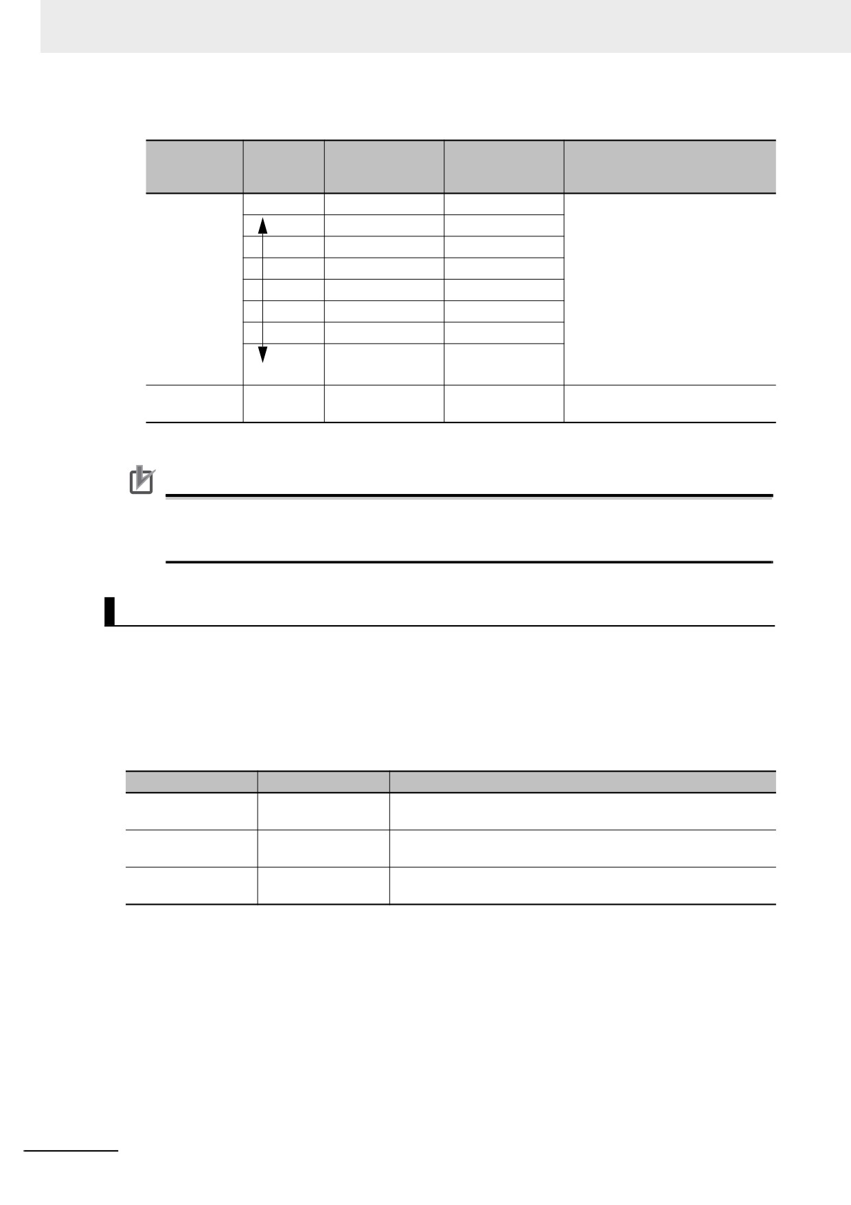
Item
Description
Values
Event Code
You can specify a number to identify the
User-defined error: 1 to 40,000
event according to the event level.
User-defined information: 40,001 to
60,000
Event Name
You can include a title for the event.
128 characters max.
Event Level
You can specify the level of the event.
User-defined error: User fault levels: 1
The level is indicated with a number.
to 8
The lower the number is, the higher the
User-defined information: User informa-
level is.
tion
Group
You can specify a group name to repre-
32 characters max.
sent the location or type of the event.
There are no restrictions on the charac-
You can use user-defined groupings for
ters that can be used. Case sensitive.
the events.
Reserved words: None
Details
You can include a message that
1,024 characters max.
describes the event. The user can enter
There are no restrictions on the charac-
any text string. The message is used
ters that can be used. Case sensitive.
when the event is displayed on the Sys-
Reserved words: None
mac Studio or an HMI.
Error details that are
Refer to the additional information that is
128 characters max.
displayed on the HMI
given below on displaying user mes-
There are no restrictions on the charac-
when a major fault level
sages on an HMI when a major fault
ters that can be used.
Controller error occurs
level Controller error occurs for more
Case sensitive. Reserved words: None
details.
Comment
The comment is attached for each set of
table entries.
Additional Information
You can set up to nine different languages for the same event code for different regions and
users. On the Sysmac Studio, you can import an Event Setting Table from a Microsoft Excel file
via the clipboard.
8
Additional Information
Displaying User Messages on an HMI When a Major Fault Level Controller Error Occurs:
When a major fault level Controller error occurs, the user program execution stops.
The NY-series Controllers can display user messages on an HMI when a major fault level Con-
troller error occurs. You can set the display messages under the list of user-defined events in the
Event Setting Table on the Sysmac Studio.
8-59
8 Controller Functions
z Event Levels and Event Codes
Range of corre-
Event classi-
Event level cate-
Level
sponding event
Description
fication
gory*
code
User-defined
High
User fault Level1
1 to 5000
Select from eight levels.
errors
User fault Level2
5001 to 10000
User fault Level3
10001 to 15000
User fault Level4
15001 to 20000
User fault Level5
20001 to 25000
User fault Level6
25001 to 30000
User fault Level7
30001 to 35000
User fault Level8
35001 to 40000
Low
User-defined
Lowest
User Information
40001 to 60000
The event type is user-defined
Information
information.
* User-defined error levels are separate from Controller error levels.
Precautions for Correct Use
If you update the Event Setting Table and transfer it to the Controller, the event logs for user-
defined events still contain old information. This can result in inconsistencies with the new Event
Setting Table. Program operations with caution.
Related Instructions
There are instructions that you can use to create and check user-defined errors and to clear existing
user-defined errors.
z Creating and Clearing User-defined Errors
Use the following instructions to create and reset user-defined errors and to create user-defined infor-
mation. Up to 32 events per level can occur simultaneously, for a total of 256 possible simultaneous
events.
Instruction name
Instruction
Description
Create User-defined
SetAlarm
The SetAlarm instruction creates a user-defined error.
Error
Reset User-defined
ResetAlarm
The ResetAlarm instruction resets a user-defined error.
Error
Create User-defined
SetInfo
The SetInfo instruction records the specified user-defined informa-
Information
tion in the event log.
z Checking for User-defined Errors
You can use the Get User-defined Error Status (GetAlarm) instruction to obtain the status of the cur-
rent user-defined errors and the highest priority event level and code of the current user-defined
errors.
8-60
8 Controller Functions
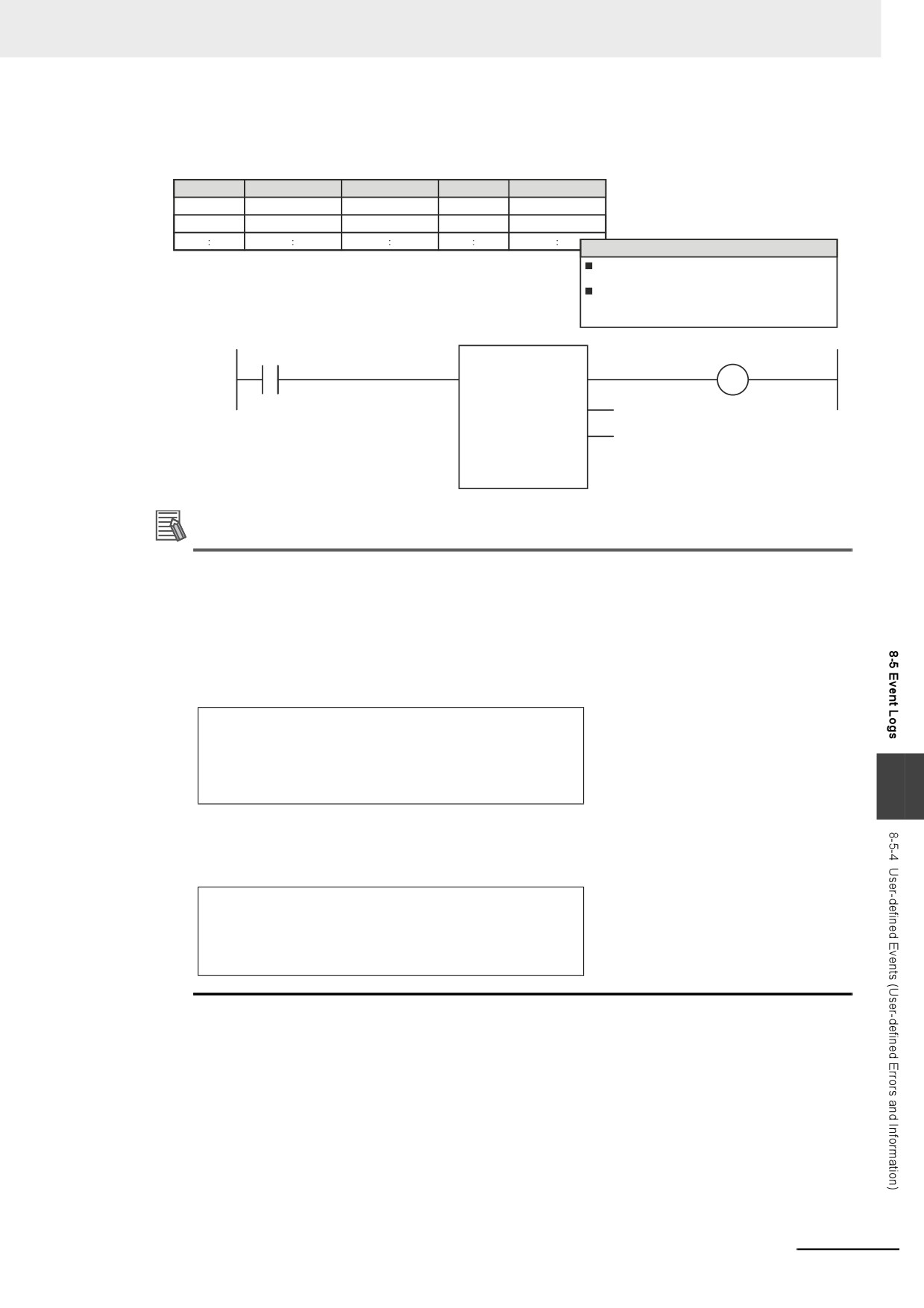
Example:
Event Setting Table
Event code
Event name
Level
Group
Details
10001
Failure X
User fault Level3
Control A (001)
Details
Description
Failure X occurred.
Correction
Perform safety checks and handle the problem
according to the cause code.
Actual Programming
Detection condition
Error
GetAlarm
EN
Level
Code
Additional Information
You can use user-defined errors to add a message on possible corrections or other information
when a Controller error occurs. Use instructions such as the GetPLCError instruction to obtain
information about the error status or event code when a Controller error occurs. You can then
use the information to trigger a user-defined error.
Example 1
When a Low Battery Voltage error occurs, the event code (16#000B0000) is obtained and the
following message is displayed.
Battery is dead.
Apply power for at least five minutes before changing the
Battery.
Install a new Battery within five minutes of turning OFF the
8
power supply.
Example 2
When a partial fault level Controller error occurs, the event error level is obtained (highest level
status: 2) and the following message is displayed.
A device failed. Call the following number for support.
Repair Contact
Hours: 8:00 AM to 9:00 PM
TEL: xxx-xxxx-xxxx
8-61

8 Controller Functions
System-defined Variables Related to User-defined Errors
Variable
Data
Meaning
Description
R/W
name
type
_AlarmFlag
User-defined
The bit corresponding to the event level is TRUE while
WORD
R
Error Status
there is a user-defined error. Bits 00 to 07 correspond to
user fault levels 1 to 8.
Records in Event Log
An event is recorded in the event log when you create user-defined information or a user-defined error,
or when you use the ResetAlarm instruction to reset an error. When this happens, the time, event code,
event level, and attached information 1 and 2 are recorded in the user-defined event log in the event
logs.
Reset User-defined Errors
User-defined errors are cleared when the power supply to the NY-series Controller is turned ON. You
can also clear errors with the Sysmac Studio, the Reset User-defined Error instruction (ResetAlarm)
and an HMI.
Refer to the Sysmac Studio Version 1 Operation Manual (Cat. No. W504) for details.
8-62
8 Controller Functions
8-6
Changing Event Levels
Errors, status changes, and user-defined events that occur in the NY-series Controller are all called
events. You can tell what type of event has occurred by viewing the display in Sysmac Studio, or by
checking the indicators on the Industrial PC.
There are two types of events: Controller events that are defined in the system and user-defined
events. The Controller events are further classified into five event levels. Refer to Event Levels on page
8-52 for details on event levels.
You can change the event levels that are assigned to some of the Controller events.
8-6-1
Applications of Changing Event Levels
The lighting pattern for the indicators on the Industrial PC is predefined according to the event level that
is assigned to each Controller event. You can change the event level for some events to change how
the Controller operates when that event occurs.
For example, the ERROR indicator flashes for minor fault level events and stays unlit for observation
level events. You can change the lighting pattern of the ERROR indicator so that it goes out or flashes
for a given event.
Refer to the NY-series Troubleshooting Manual (Cat. No. W564) for details on how the Controller oper-
ates for different event levels.
8-6-2
Events for Which the Event Level Can Be Changed
Whether an event level can be changed depends on the specific event.
Refer to the NY-series Troubleshooting Manual (Cat. No. W564) for details on the types and levels of
the Controller events, and whether the event levels can be changed.
8
8-63
8 Controller Functions
8-6-3
Procedure to Change an Event Level
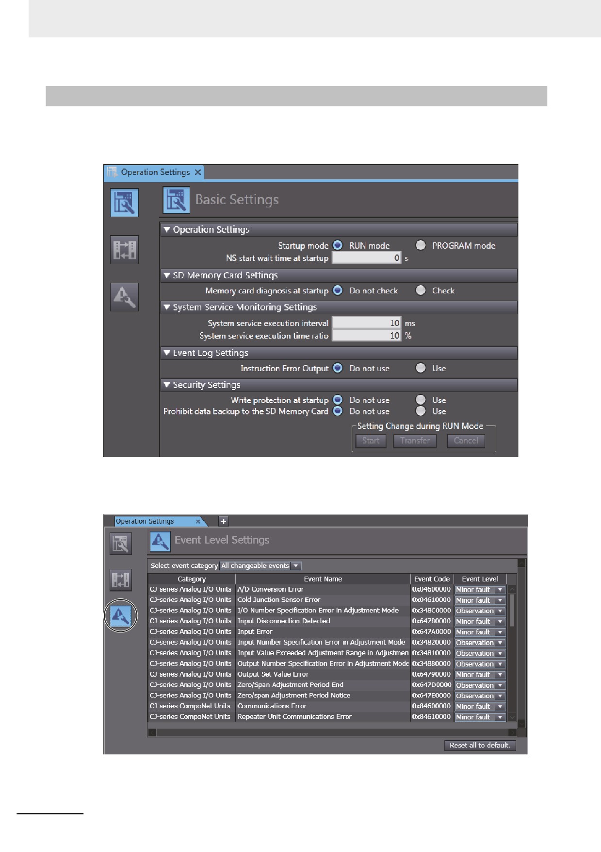
1 Double-click Operation Settings under Configurations and Setup − Controller Setup in the
Sysmac Studio. Or right-click Operation Settings and select Edit from the menu.
The Basic Settings Display is displayed on the Operation Setting Tab Page in the Edit Pane.
2 Click the Event Level Settings Button.
A list of the events for which you can change the event level is displayed.
3 Change the levels of the required events in the Event Level column.
8-64
8 Controller Functions
Precautions for Correct Use
If you change an event level on the Sysmac Studio and download the event level setting to the
Controller when the event already exists on the Controller, the event will be reset when the
download is started. If the same event occurs again while the download is in progress, the Con-
troller will operate according to the previous event level. If the same event occurs after the down-
load is completed, the Controller will operate according to the new level.
8
8-65
8 Controller Functions
8-66
Backup Functions
This section describes the backup functions for the settings in an NY-series Controller.
There are different types of backup functions that handle different data or different stor-
age locations. First an overall description of the backup functions is provided followed
by descriptions of the individual functions.
9-1
The Backup Functions
9-3
9-1-1
Applications of Backup Functions
9-3
9-1-2
Data That Is Backed Up
9-4
9-1-3
Types of Backup Functions
9-5
9-1-4
Relation between the Different Types of Backup Functions and Data Groups
9-7
9-1-5
Applicable Range of the Backup Functions
9-8
9-2
SD Memory Card Backups
9-10
9-2-1
Backup (Controller to Virtual SD Memory Card)
9-11
9-2-2
Verify (between Controller and Virtual SD Memory Card)
9-15
9-3
Disabling Backups to SD Memory Cards
9-19
9-4
Sysmac Studio Controller Backups
9-20
9-4-1
Backup (Controller to Computer)
9-21
9
9-4-2
Restore (Computer to Controller)
9-22
9-4-3
Verify (between Controller and Computer)
9-23
9-5
Importing and Exporting Sysmac Studio Backup File Data
9-24
9-6
Sysmac Studio Variable and Memory Backup Functions
9-25
9-6-1
Applicable Data for Sysmac Studio Variable and Memory Backup Functions 9-25
9-6-2
Using Sysmac Studio Variable and Memory Backup Functions
9-25
9-6-3
Compatibility between NY-series Controller Models
9-25
9-7
Backup Functions When EtherCAT Slaves Are Connected
9-26
9-7-1
Backed Up EtherCAT Slave Data
9-26
9-7-2
Backup Support Depending on the Controller Status
9-27
9-7-3
Conditions for Restoring EtherCAT Slave Data
9-28
9-7-4
EtherCAT Slaves for Which You Can Back Up Data
9-29
9-8
Backup Functions When EtherCAT Slave Terminals Are Connected . . . 9-31
9-8-1
Backing Up Data in an EtherCAT Slave Terminal
9-31
9-8-2
Backup Support Depending on the EtherCAT Slave Terminal Status
9-32
9-8-3
Conditions for Restoring EtherCAT Slave Terminal Data
9-32
9-9
Backup-related Files
9-33
9-1
9 Backup Functions
9-9-1
Types of Backup-related Files
9-33
9-9-2
Specifications of a Backup File
9-34
9-9-3
Specifications of a Restore Command File
9-35
9-9-4
Specifications of a Controller Verification Results File
9-38
9-9-5
Specifications of an EtherCAT Verification Results File
9-39
9-9-6
Specifications of an EtherCAT Slave Terminal Verification Results File
9-40
9-10 Compatibility between Backup-related Files
9-41
9-10-1
Compatibility between Backup Functions
9-41
9-10-2
Compatibility between NY-series Controller Models
9-42
9-10-3
Compatibility between Unit Versions of NY-series Controllers
9-43
9-11 Functions That Cannot Be Executed during Backup Functions
9-44
9-2
9 Backup Functions
9-1
The Backup Functions
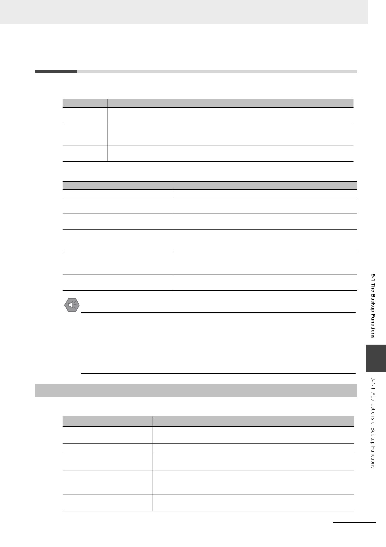
The following three functions are supported for data backup for an NY-series Controller.
Function
Description
Backing up
You can back up all of the data in the Controller to a Virtual SD Memory Card or to a computer.
data
The file that is saved is called a backup file.
Restoring data
You can transfer the contents of a backup file on the Virtual SD Memory Card or computer to
the Controller. The data in the Controller is restored to the data at the time the backup file was
made.
Verifying data
You can compare the contents of a backup file on the Virtual SD Memory Card or computer
with the data in the Controller to see if they are the same.
The following items are described for the backup functions.
Item
Description
Applications of backup functions
Effective usage of the backup functions is described.
Examples of operating procedures for
The backup functions are executed with simple procedures. Exam-
the backup functions
ples are provided.
Data that is backed up
The data that can be saved with the backup functions from the con-
nected Units and slaves is described.
Types of backup functions
There are different types of backup functions that differ in where the
data is saved. The types of backup functions and the difference
between them are described.
Relation between the different types of
Different types of backup functions handle different data groups. The
backup functions and data groups
relation between the different types of backup functions and data
groups is described.
Applicable range of the backup functions
The connected Units and slaves for which you can save data with the
backup functions are described.
Precautions for Safe Use
We recommend that you back up the present values of variables while the retained variables are
not refreshed.
If you back up while the values of retained variables are refreshed, the data may not be saved
correctly.
• Structure members whose data size is 16 bits or more
9
• Array elements whose data size is 16 bits or more
9-1-1
Applications of Backup Functions
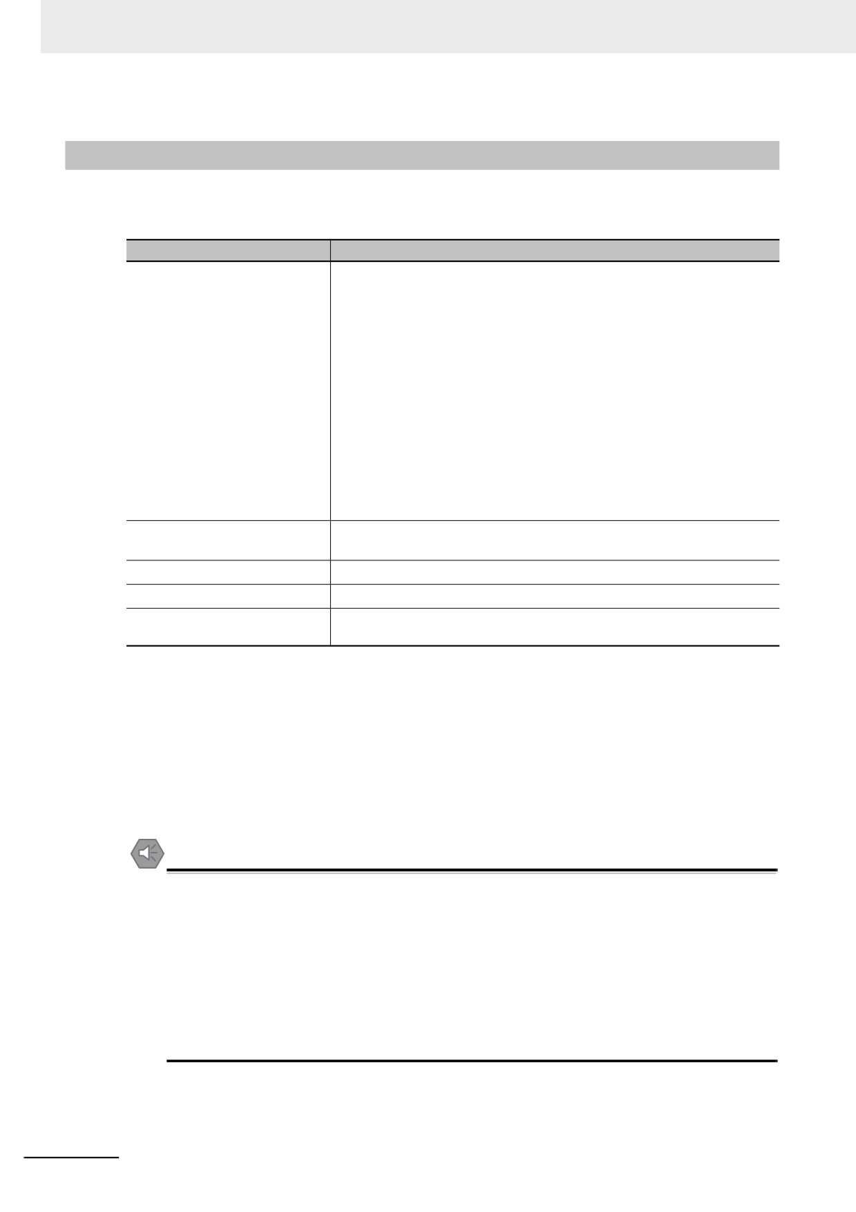
You can use the backup functions in the following instances.
Item
Application
Program and setting changes
When you change the user program and settings for equipment that is cur-
rently in operation.
Hardware replacements
When you replace the hardware for Industrial PCs, Units, or slaves.
Troubleshooting equipment fail-
When you want to save data in the Controller to analyze the cause of an
ures
error that occurs in the equipment.
Equipment backup and recovery
When an error occurs in the equipment, and when you want to restore the
equipment with data from a normal operating status. When you want to
backup the data in the equipment while it is in operation.
Manufacture of equipment
When you want to manufacture the same equipment and need to transfer
the data from the existing equipment to new equipment in its initial state.
9-3
9 Backup Functions
9-1-2
Data That Is Backed Up
The following data is backed up.
This section describes the backup functions based on the following data groups for the backup data.
Data group
Data items
User program and settings
EtherCAT configuration (EtherCAT slave configuration and EtherCAT master
settings)
Unit Configuration and Unit Setup
I/O Map
Controller Setup (Operation Settings and Built-in EtherNet/IP Port Settings)
Motion Control Setup
Cam Data Settings
Event Setup
Task Setup
Data Trace Settings
Tag Data Link Tables
Controller name
Operation authority verification
User program execution ID in user program
POUs
Data (data types and global variables)
IP address of built-in EtherNet/IP
Of the TCP/IP Settings in the Built-in EtherNet/IP Port Settings, setting type,
port*1
IP address, subnet mask, and default gateway
Present values of variables
Values of variables with a Retain attribute*2
Units and slaves settings
Backup parameters for EtherCAT slaves*3
Absolute encoder home offset
The set value to restore the actual position of a Servo Drive with an absolute
encoder
*1. With a combination of the Controller with unit version 1.14 or later and Sysmac Studio version 1.18 or higher, IP
address of the Built-in EtherNet/IP Port Settings can be used as a data group. IP address is included in the user
program and settings other than the above combination.
*2. Of the system-defined variables with a Retain attribute, some variables are not applicable for the data backup
function. Refer to A-4 Specifications for Individual System-defined Variables for details on the specifications for
individual system-defined variables.
*3. A part or all of the set parameters are not backed up for some EtherCAT slave models. For the details on the
target EtherCAT slaves for the data backup function, refer to 9-7-4 EtherCAT Slaves for Which You Can Back
Up Data.
Precautions for Safe Use
Precautions on the Absolute Encoder Home Offset
The absolute encoder home offsets are backed up with a non-volatile memory in the CPU Unit
as absolute encoder information. If any of the following conditions is met, clear the absolute
encoder home offsets from the list of data items to restore, and then restore the data. Then,
define the absolute encoder home again. If you do not define home, unintended operation of the
controlled system may occur.
• The Servomotor or Servo Drive was changed since the data was backed up.
• The absolute encoder was set up after the data was backed up.
• The absolute data for the absolute encoder was lost.
9-4
9 Backup Functions
9-1-3
Types of Backup Functions
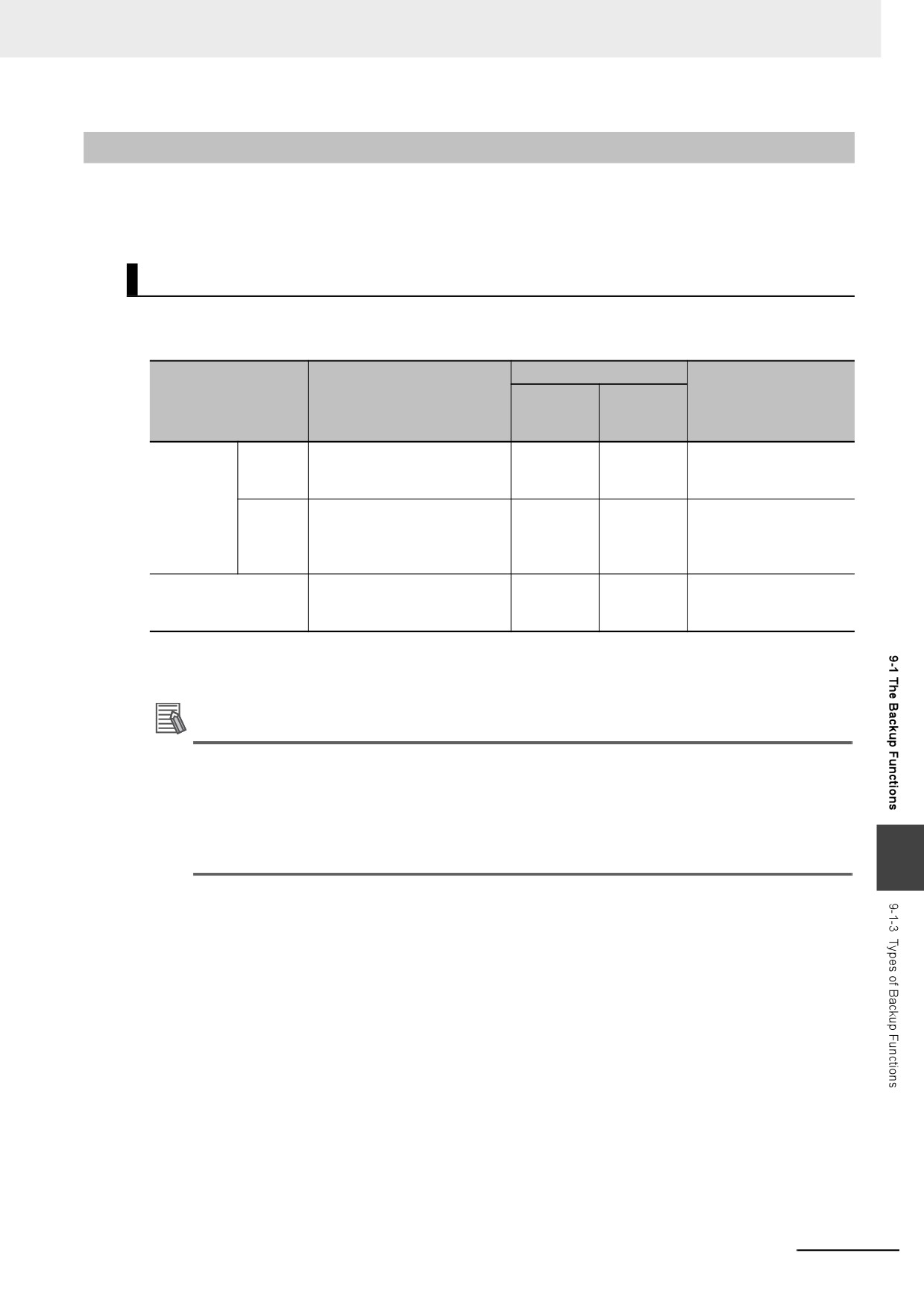
There are backup functions for the NY-series Controllers that save data to Virtual SD Memory Cards
and others that save data to a computer. Also, there are three methods used to execute the backup
functions: the system-defined variables, the Sysmac Studio, and the Industrial PC Support Utility.
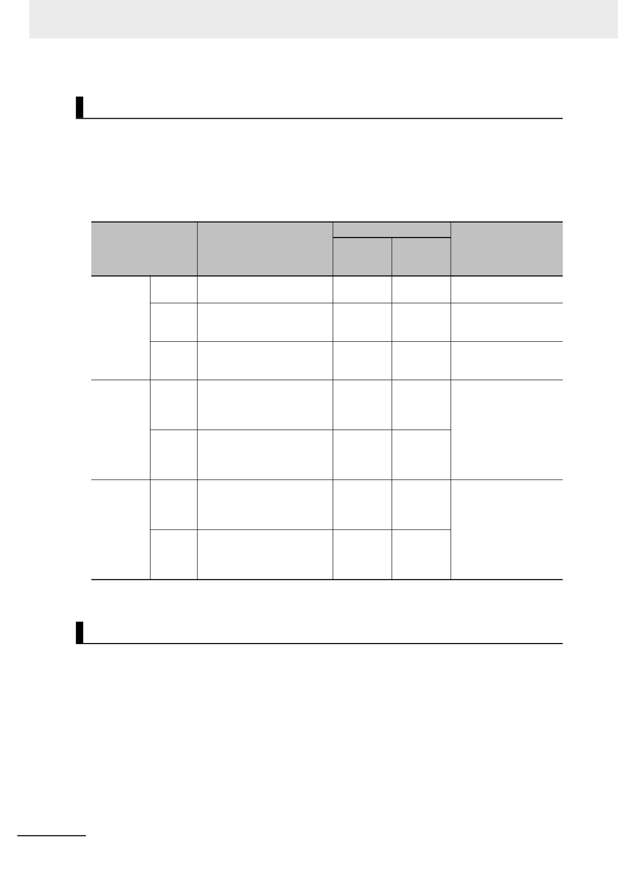
Functions That Save Data to Virtual SD Memory Cards
The SD Memory Card backup functions are used to back up and compare data on Virtual SD Memory
Cards. The related function includes disabling backups to SD Memory Cards.
Operating method
System-
Function name
Description
Sysmac
Reference
defined
Studio
variables
SD Mem-
Backing
The Controller data is saved in
9
9-2-1 Backup
(
Controller
ory Card
up data
a backup file on the Virtual SD
to Virtual SD Memory
backups
Memory Card.
Card)
Verifying
The Controller data and the
9
9-2-2 Verify (between
data
data in a backup file on the Vir-
Controller and Virtual SD
tual SD Memory Card are
Memory Card)
compared.
Disabling backups to
You can disable backing up
9
9-3 Disabling Backups to
SD Memory Cards
data to Virtual SD Memory
SD Memory Cards
Cards.
Additional Information
• To restore the backup files that are saved on the Virtual SD Memory Card to the Controller,
specify the shared folder being set on the Virtual SD Memory Card with the restore operation
of the Controller backup functions for Industrial PC Support Utility.
• You can also restore with the Sysmac Studio Controller backup functions. In this case, you
need to use an external storage to save the backup files, which are saved in the shared folder
9
being set on the Virtual SD Memory Card, in the computer that the Sysmac Studio is installed.
9-5
9 Backup Functions
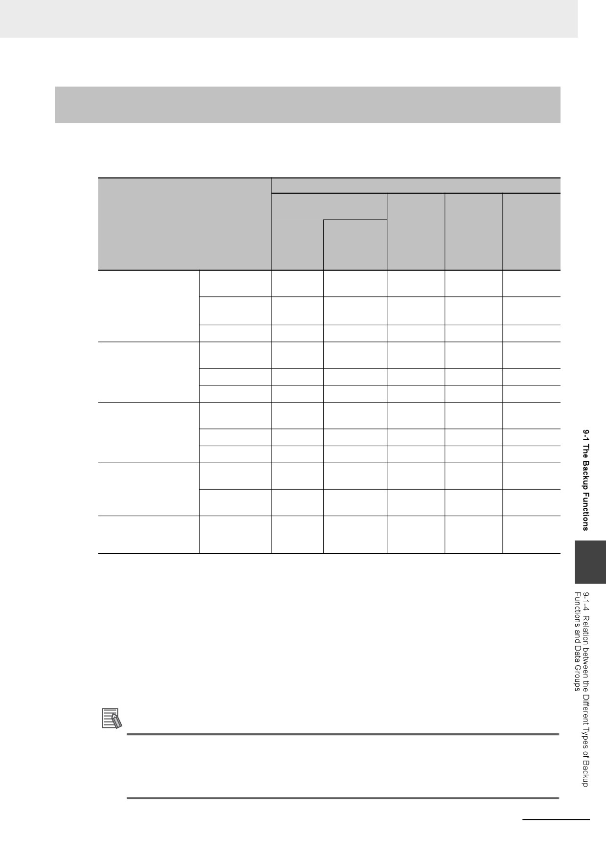
Functions That Save Data to the Computer
The Sysmac Studio Controller backup functions are used to back up, restore, and compare data on the
computer.
Importing and exporting Sysmac Studio backup file data are used to save and read different types of
data between the Sysmac Studio projects and backup files on the computer without using a Controller.
The Sysmac Studio variable and memory backup functions are used to back up the present values
saved on a non-volatile memory to the computer and restore them from the computer.
Operating method
System-
Function name
Description
Sysmac
Reference
defined
Studio
variables
Sysmac
Backing
The Controller data is saved in
9
9-4-1 Backup (Controller
Studio
up data
a backup file on the computer.
to Computer)
Controller
Restor-
The data in a backup file on
9-4-2 Restore (Computer
9
backups
ing data
the computer is transferred to
to Controller)
the Controller.
Verifying
The Controller data and the
9
9-4-3 Verify (between
data
data in a backup file on the
Controller and Com-
computer are compared.
puter)
Sysmac
Export-
The data is exported from the
9
9-5 Importing and
Studio
ing data
project on the Sysmac Studio
Exporting Sysmac Studio
to a backup file without using a
Backup File Data
Importing
Controller.
and export-
ing Sysmac
Import-
The data in the backup file is
9
Studio
ing data
imported into the Sysmac Stu-
backup file
dio project without using a
data
Controller.
Sysmac
Backing
You can back up the present
9
9-6 Sysmac Studio Vari-
Studio
up data
values of data that is saved on
able and Memory
a non-volatile memory to an
Backup Functions
variable
XML file on the computer.
and mem-
ory backup
Restor-
You can restore the present
9
functions
ing data
values of data that is saved on
a non-volatile memory from
the computer to the Controller.
Functions That Save Data to the Folder in Windows
The Controller backup functions for Industrial PC Support Utility are used to back up, restore, and
compare data on the folder in Windows.
Refer to the NY-series Industrial Panel PC / Industrial Box PC Setup User’s Manual (Cat. No. W568) for
details on the Controller backup functions for Industrial PC Support Utility.
9-6
9 Backup Functions
9-1-4
Relation between the Different Types of Backup Functions and
Data Groups
Different types of backup functions handle different data groups. The relation between the different
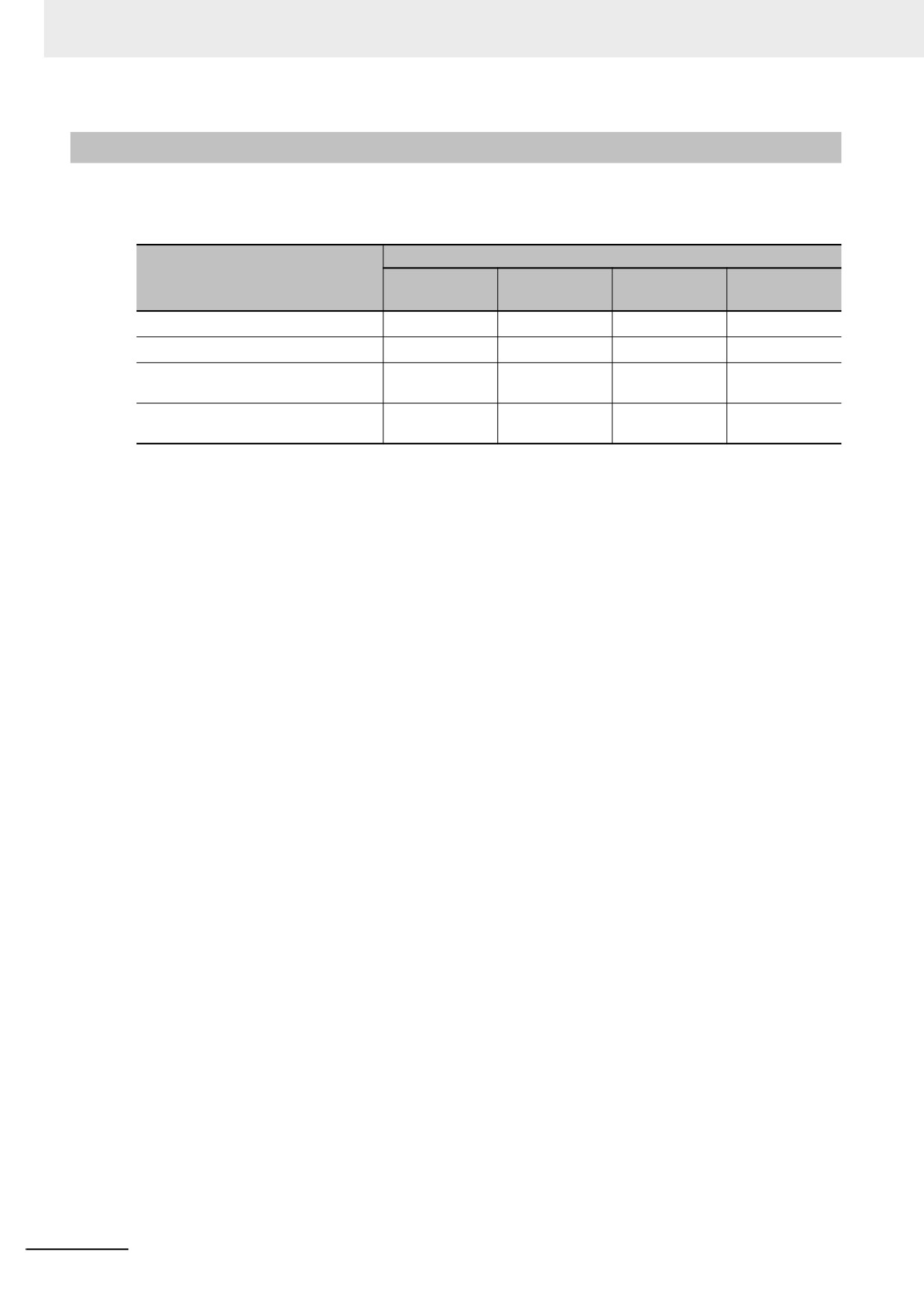
types of backup functions and data groups is given in the following table.
(OK: Applicable, NA: Not applicable)
Data group
User program and set-
tings
Absolute
Present
Units and
Type of backup function
IP address
encoder
values of
slaves set-
of built-in
home off-
variables
tings
EtherNet/IP
sets
port*1
SD Memory Card
Backing up
OK
OK
OK*2
OK
OK
backups
data
Restoring
OK
OK
OK*2
OK
OK
data*3
Verifying data*3
OK*4
OK
NA
OK
NA
Sysmac Studio Con-
Backing up
OK
OK
OK*2
OK*5
OK
troller backups
data
Restoring data
OK
OK
OK*2
OK*5
OK
Verifying data
OK*4
OK
NA
OK*5
NA
Controller backups for
Backing up
OK
OK
OK*2
OK*5
OK
Industrial PC Support
data
Utility
Restoring data
OK
OK
OK*2
OK*5
OK
Verifying data
OK*4
OK
NA
OK*5
NA
Importing and export-
Exporting
OK*6
OK
NA
NA
NA
ing Sysmac Studio
backup file data
backup file data
Importing
OK*6
OK
NA
OK
NA
backup file data
Sysmac Studio vari-
Backing up and
NA
NA
OK*2
NA
OK
able and memory
restoring data
backup functions
9
*1. With a combination of the Controller with unit version 1.14 or later and Sysmac Studio version 1.18 or higher, IP
address of the Built-in EtherNet/IP Port Settings can be used as a data group. IP address is included in the user
program and settings other than the above combination.
*2. The backup data is processed only for the present values of variables that are specified for retention with the
Retain attribute.
*3. For all of the data groups except for the user program and setting group, only the items that are specified to be
restored in the restore command file are restored.
*4. Of the user program and setting data groups, the Data Trace Settings are not compared.
*5. If the EtherCAT slaves are specified for the backup, parameters for the EtherCAT slaves are backed up.
*6. The following data is not processed: Tag data link settings for the built-in EtherNet/IP port, operation authority
verification, and the Data Trace Settings.
Additional Information
The files that are handled for backing up variables and memory from the Sysmac Studio are not
compatible with other backup files.
Refer to 9-6 Sysmac Studio Variable and Memory Backup Functions for details on the Sysmac
Studio variable and memory backup functions.
9-7
9 Backup Functions
9-1-5
Applicable Range of the Backup Functions
Different types of backup functions handle data for different Units or slaves. The applicable Units and
slaves for each backup function are given in the following table.
(OK: Applicable, NA: Not applicable)
Units/slaves
Type of backup function
NY-series Con-
EtherCAT
EtherNet/IP
Computer and
troller
slaves*1
slaves
HMIs
SD Memory Card backups
OK
OK*2
NA
NA
Sysmac Studio Controller backups
OK
OK*2
NA
NA
Importing and exporting Sysmac Stu-
OK
OK*3
NA
NA
dio backup file data
Sysmac Studio variable and memory
OK
NA
NA
NA
backup functions
*1. EtherCAT Slave Terminals are included. If EtherCAT Slave Terminals are set for backup, the backup function
applies to both the EtherCAT Coupler Unit and the NX Units.
*2. This does not apply to Safety Control Units. Refer to the NX-series Safety Control Units User’s Manual (Cat. No.
Z930) for information on importing and exporting settings for a Safety Control Unit.
*3. Only importing data is possible. Exporting is not possible.
9-8
9 Backup Functions
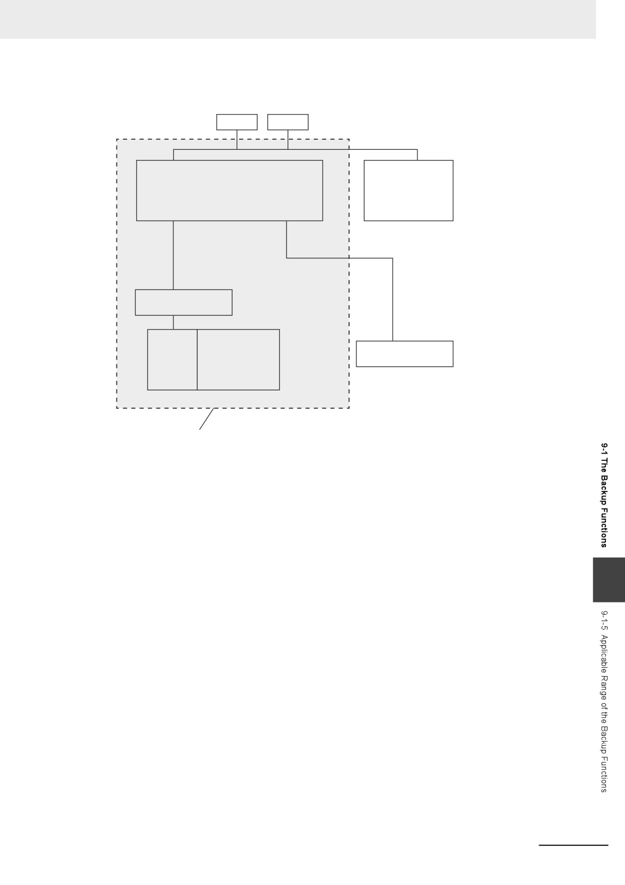
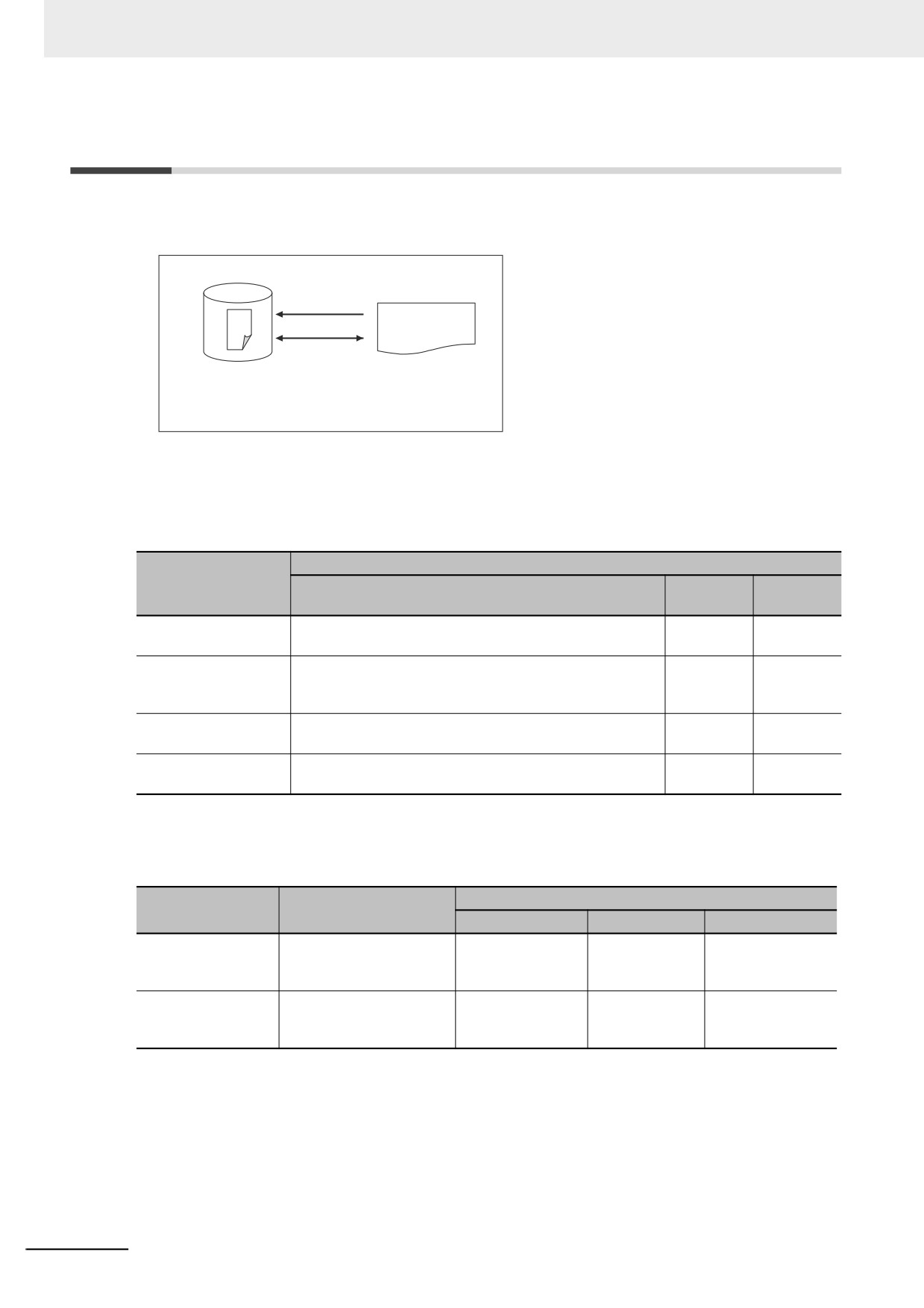
The Units and slaves that are shown in the following figure are covered by the SD Memory Card
backup functions and Sysmac Studio Controller backup functions.
Computer
HMI
NY-series Controller
NY-series Controller
EtherCAT slaves
EtherCAT
EtherNet/IP slaves
NX Units
Coupler Unit
EtherCAT Slave Terminal
Applicable range for the SD Memory Card backup
functions and Sysmac Studio Controller backup functions.
9
9-9
9 Backup Functions
9-2
SD Memory Card Backups
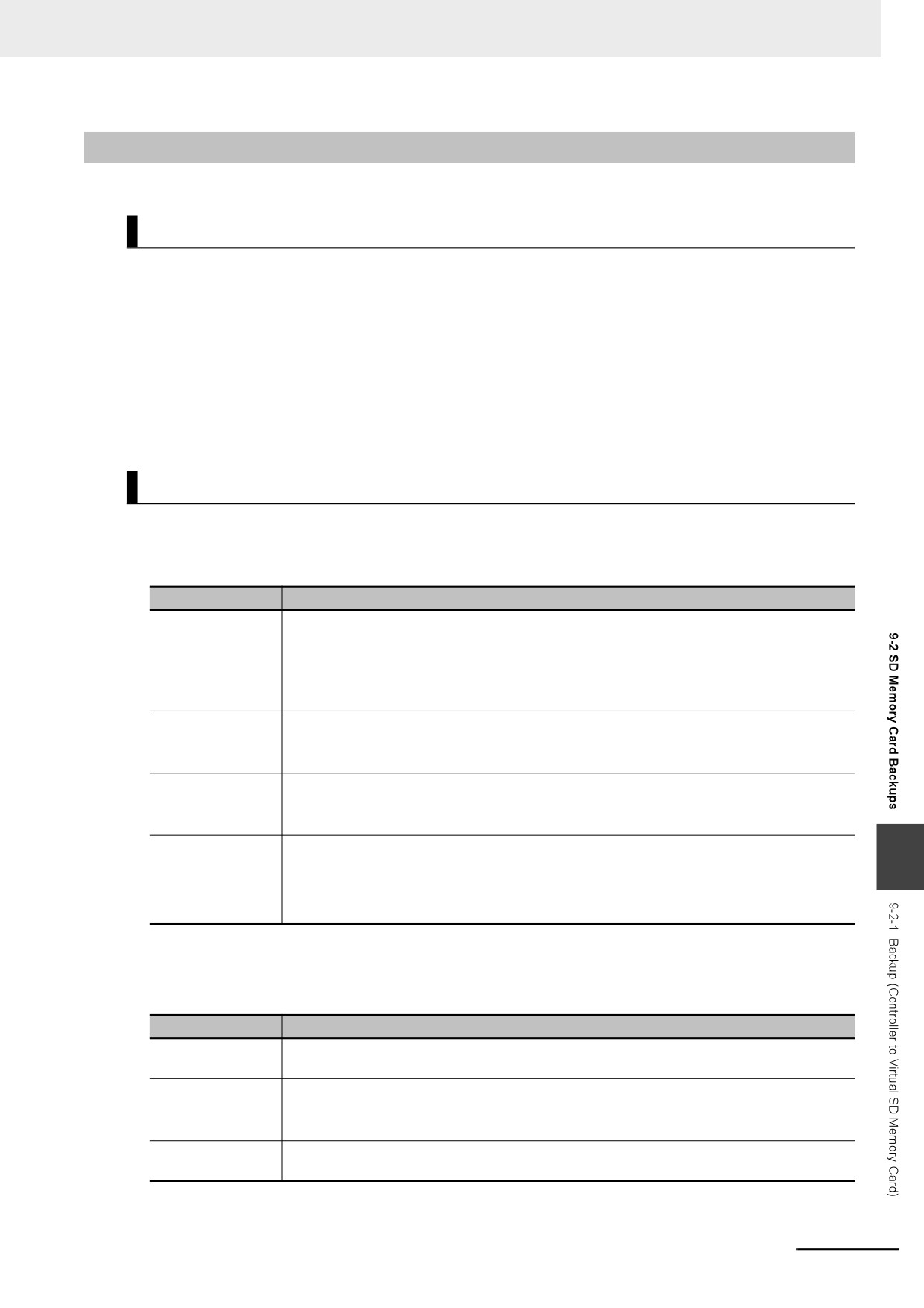
You can use Virtual SD Memory Cards to back up and verify Controller data.
Industrial PC
Virtual SD Memory Card
Backing up data
Data that is
Verifying data
backed up
Backup file
Restore command file
Automatic transfer command file
Verification results files
When you back up data, the backup file, restore command file, and automatic transfer command file
are created in the specified directory on the Virtual SD Memory Card. When you verify data, the
verification results files are created in the specified directory. All of these files are collectively referred to
as backup-related files. The functions of the backup-related files are given in the following table.
Function
File
Backing up
Verifying
Contents
data
data
Backup file
This file contains the Controller data that is handled by the
Created.
Accessed.
functions that are related to data backup.
Restore command file
This file specifies the data groups to restore when restoring
Created.
Accessed.
data. You can edit this file with a text editor on a computer
to specify the data groups to restore.
Automatic transfer
This file is not used in an NY-series Controller.
Created.
Nothing is
command file
done.
Verification results file
This file contains the verification results after data is veri-
Nothing is
Created.
fied.
done.
The execution method for the functions, applicable directory, and applicable operating modes are given
in the following table.
Applicable operating modes
Procedure
Directory*1
Backing up data
Restoring data
Verifying data
System-defined vari-
The directory that you
RUN mode and
Execution is not
RUN mode and
ables*2*3
specified in the system-
PROGRAM mode
possible.
PROGRAM mode
defined variable
SD Memory Card
The directory that you
RUN mode and
Execution is not
RUN mode and
Window in Sysmac
specified on the SD Mem-
PROGRAM mode
possible.
PROGRAM mode
Studio
ory Card Window
*1. You can specify a directory only on the Virtual SD Memory Card.
*2. This method is used to control the backup functions from an HMI. You cannot access these system-defined
variables from the user program.
*3. Make arrangements to prevent backup or verification operations from being performed on HMIs while a backup
or verification operation is in progress. Otherwise, the intended operation may not occur.
9-10
9 Backup Functions
9-2-1
Backup (Controller to Virtual SD Memory Card)
This operation is used to save data in the Controller to the Virtual SD Memory Card.
Processing Contents
• This backup operation processes all data groups.
• When you back up data, the backup file, restore command file, and automatic transfer command file
are created in the specified directory on the Virtual SD Memory Card.
• If the backup-related files are already in the specified directory, they are overwritten.
• If an error occurs while writing the backup-related files to the Virtual SD Memory Card, the previous
backup-related files will be deleted. Also, the new backup-related files will not be created.
• If an error occurs before the new backup-related files are created, the previous files are retained and
the new files are not created.
• The Virtual SD Memory Card will remain the recognition after completion of the backup.
Procedure
z Backing Up Data with the _Card1BkupCmd (SD Memory Card Backup
Command) System-defined Variable
Processing stage
Procedure
Start command
The name of the directory where the files are saved is stored in the _Card1BkupCmd.Dir-
Name (Directory Name) system-defined variable.
Example: "dirA/dirB" specifies the dirB directory inside the dirA directory.
The backup operation starts when you change the _Card1BkupCmd.ExecBkup (Execute
Backup Flag) system-defined variable to TRUE.
Cancel command
You can cancel the backup operation.
The backup operation ends in an error if you change the _Card1BkupCmd.CancelBkup
(Cancel Backup Flag) system-defined variable to TRUE.
Executing
The _Card1BkupSta.Active (Active Flag) system-defined variable changes to TRUE.
The value of the _BackupBusy (Backup Function Busy Flag) system-defined variable will
change to TRUE.
Execution results
Normal end:
9
The _Card1BkupSta.Done (Done Flag) system-defined variable changes to TRUE.
Error end:
The _Card1BkupSta.Err (Error Flag) system-defined variable changes to TRUE.
Note You cannot access these system-defined variables from the user program.
z Backing Up Data from the SD Memory Card Window on the Sysmac Studio
Processing stage
Procedure
Start command
Click the SD Memory Card Backup Button on the SD Memory Card Window in the Sys-
mac Studio, specify the directory to save the backup file in, and execute the backup.
Executing
The progress of the backup is displayed in the dialog box.
The value of the _BackupBusy (Backup Function Busy Flag) system-defined variable will
change to TRUE.
Execution results
A message will appear when the backup is completed. You will then be asked to confirm
whether to verify the backup data.
Refer to the Sysmac Studio Version 1 Operation Manual (Cat. No. W504) for specific procedures.
9-11
9 Backup Functions
z Backing Up Data with Special Instruction
Processing stage
Procedure
Start command
Execute the BackupToMemoryCard instruction in the user program.
Executing
The value of the Busy output variable from the BackupToMemoryCard instruction will
change to TRUE.
The value of the _BackupBusy (Backup Function Busy Flag) system-defined variable will
change to TRUE.
Execution results
Normal end:
The value of the Done output variable from the BackupToMemoryCard instruction changes
to TRUE.
Error end:
The value of the Error output variable from the BackupToMemoryCard instruction changes
to TRUE.
The error code is stored in the ErrorID output variable from the BackupToMemoryCard
instruction.
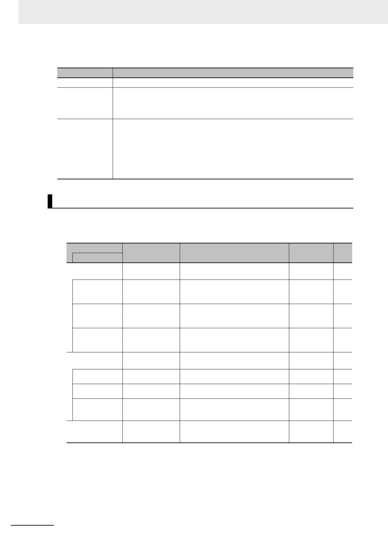
Related System-defined Variables
The system-defined variables that are related to the operation when system-defined variables are used
to back up data are shown below. Refer to A-4 Specifications for Individual System-defined Variables
for details on system-defined variables.
Variable
Meaning
Function
Data type
R/W
Member name
_Card1BkupCmd*1
SD Memory Card
_sBKUP_CMD
RW
Backup Commands
ExecBkup*1
Execute Backup
Change this variable to TRUE to back up
BOOL
RW
Flag
Controller data to a Virtual SD Memory
Card.
CancelBkup*1
Cancel Backup Flag
Change this variable to TRUE to cancel
BOOL
RW
backing up data to a Virtual SD Memory
Card.
DirName*1
Directory Name
Use this variable to specify the directory
STRING(64)
RW
name in the Virtual SD Memory Card for
which to back up data.
_Card1BkupSta*1
SD Memory Card
_sBKUP_STA
R
Backup Status
Done*1
Done Flag
TRUE when a backup is completed.
BOOL
R
Active*1
Active Flag
TRUE when a backup is in progress.
BOOL
R
Err*1
Error Flag
TRUE when processing a backup ended
BOOL
R
in an error.
_BackupBusy
Backup Function
TRUE when a backup, restoration, or
BOOL
R
Busy Flag
verification is in progress.
*1. You cannot access these system-defined variables from the user program.
9-12
9 Backup Functions
Additional Information
• Refer to the NA-series Programmable Terminal Software User's Manual (Cat. No. V118) for
information on mapping variables when you connect an NA-series PT to the NY-series Con-
troller.
• Refer to A-7 Registering a Symbol Table on the CX-Designer for the procedure to register these
system-defined variables in the variable table of the CX-Designer when you connect an NS-
series PT to the NY-series Controller.
Timing Charts
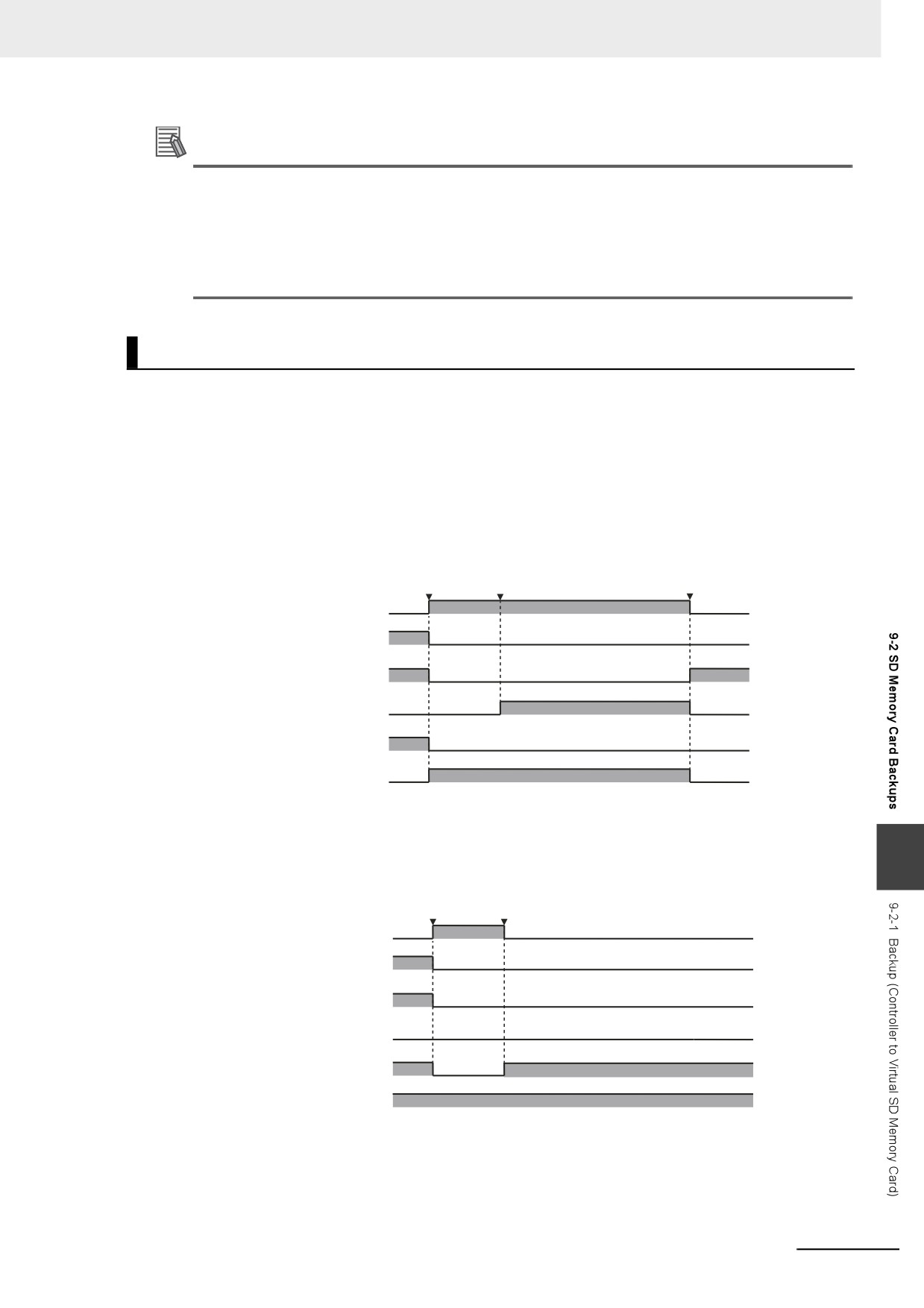
The operation of the system-defined variables when they are used to backup data is shown below.
In the charts, “pre-execution checks” indicates processing to check whether there is a Virtual SD Mem-
ory Card and other items before the backup starts. The value of _Card1BkupSta.Active (Active Flag)
changes to TRUE only after all of the pre-execution checks are cleared and the actual backup is
started.
z Normal Operation
Backup start
Pre-execution
command
checks cleared.
Normal end
TRUE
_Card1BkupCmd.ExecBkup
FALSE
TRUE
_Card1BkupCmd.CancelBkup
FALSE
TRUE
_Card1BkupSta.Done
FALSE
TRUE
_Card1BkupSta.Active
FALSE
TRUE
_Card1BkupSta.Err
FALSE
TRUE
_BackupBusy
FALSE
z Operation When the Backup Cannot Start Because Another Backup Function
9
Is in Progress
Backup start
Pre-execution
command
checks not cleared.
TRUE
_Card1BkupCmd.ExecBkup
FALSE
TRUE
_Card1BkupCmd.CancelBkup
FALSE
TRUE
_Card1BkupSta.Done
FALSE
TRUE
_Card1BkupSta.Active
FALSE
TRUE
_Card1BkupSta.Err
FALSE
TRUE
_BackupBusy
FALSE
9-13
9 Backup Functions
z Operation When the Backup Fails After a Normal Start
Backup start
Pre-execution
Error occurred
command
checks cleared.
during backup.
TRUE
_Card1BkupCmd.ExecBkup
FALSE
TRUE
Card1BkupCmd.CancelBkup
FALSE
TRUE
_Card1BkupSta.Done
FALSE
TRUE
_Card1BkupSta.Active
FALSE
TRUE
_Card1BkupSta.Err
FALSE
TRUE
_BackupBusy
FALSE
z Operation When the Backup Is Canceled While the Backup Is in Progress
The time required to stop the backup operation after it is canceled depends on the progress of the
backup operation.
Backup cancel
command
Backup start
Pre-execution
Backup stopped
command
checks cleared.
with an error.
TRUE
_Card1BkupCmd.ExecBkup
FALSE
TRUE
_Card1BkupCmd.CancelBkup
FALSE
TRUE
_Card1BkupSta.Done
FALSE
TRUE
_Card1BkupSta.Active
FALSE
TRUE
_Card1BkupSta.Err
FALSE
_BackupBusy
TRUE
FALSE
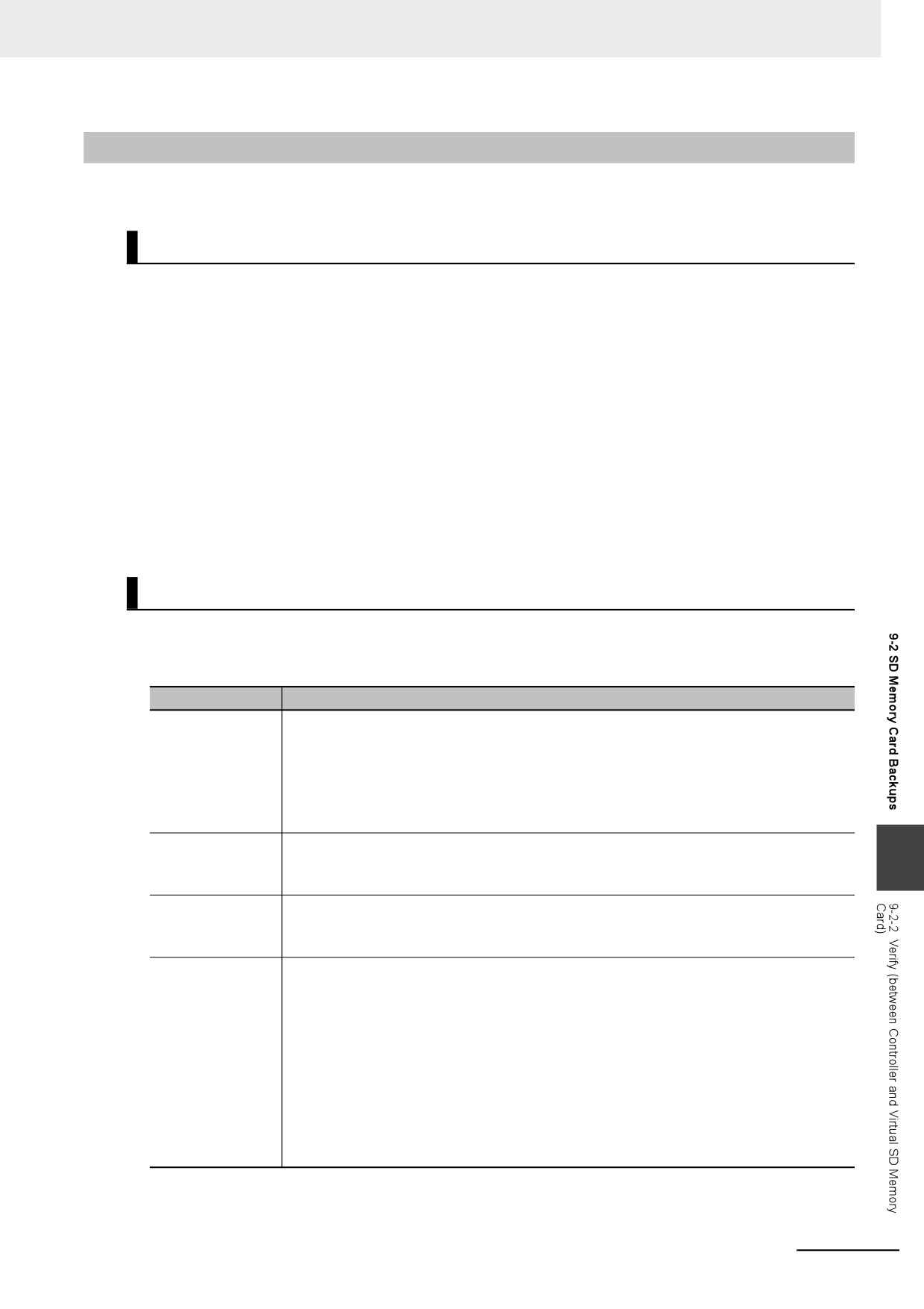
Processing Time and Backup File Size
The time that is required to back up the data depends on factors such as the operating mode, Unit con-
figuration, and user program. The size of the backup file depends on factors such as the Unit configura-
tion and user program. Some guidelines for the backup time and backup file size are given in the
following table.
Con-
Number of
User pro-
nected
Operating
user-
gram mem-
Backup
Backup file
Controller
Ether-
mode
defined
ory size
time (s)
size (Mbytes)
CAT
POUs
(Mbytes)
slaves
NY5 2-
PROGRAM
*1
72
3.82
Approx. 155
20.27
mode
*1. Thirty-two R88D-KNA-ECT AC Servo Drives and five NX-ECC201 EtherCAT Coupler Units. The EtherCAT Cou-
pler Unit consists of the following NX Units.
Five each of the NX-PD1000, NX-AD4608, and NX-DA3605. Sixty-four each of the NX-ID3343 and NX-OD3153.
9-14
9 Backup Functions
9-2-2
Verify (between Controller and Virtual SD Memory Card)
You can compare the Controller data and the data in a backup file on the Virtual SD Memory Card.
Processing Contents
• The Controller data and the data in a backup file that is saved in the specified directory of the Virtual
SD Memory Card are compared.
• The data groups that are processed by the verification operation are specified in the RestoreCom-
mand.ini file (restore command file).
• The present values of variables and the absolute encoder home offsets are not compared because
these values may change while the verification is in process.
• When you verify the data, the verification results file (VerifyResult.log) is created in the specified
directory. The verification results are stored in this file. If a verification results file already exists in the
specified directory, it will be overwritten.
• If there is not a restore command file in the specified directory of the Virtual SD Memory Card, all of
the data from the backup files in the specified directory that can be compared will be compared.
• If the Unit and slave configuration in the backup file is not the same as the actual configuration of the
Controller, a Verification Error will occur.
• The Virtual SD Memory Card will remain the recognition after completion of the backup.
Procedure
z
_Card1BkupCmd (SD Memory Card Backup Command) System-defined
Variable
Processing stage
Procedure
Start command
The name of the directory where the files are saved is stored in the _Card1BkupCmd.Dir-
Name (Directory Name) system-defined variable.
Example: "dirA/dirB" specifies the dirB directory inside the dirA directory.
The verification operation starts when you change the _Card1BkupCmd.ExecVefy (Execute
Verify Flag) system-defined variable to TRUE.
Cancel command
You can cancel the verification operation.
9
The verification operation ends in an error if you change the _Card1BkupCmd.CancelVefy
(Cancel Verify Flag) system-defined variable to TRUE.
Executing
The _Card1VefySta.Active (Active Flag) system-defined variable changes to TRUE.
The value of the _BackupBusy (Backup Function Busy Flag) system-defined variable will
change to TRUE.
Execution results
Normal end with no differences found:
The _Card1BkupSta.Done (Done Flag) and the _Card1BkupSta.VefyRslt (Verify Result
Flag) system-defined variables change to TRUE.
Normal end with differences found:
The _Card1BkupSta.Done (Done Flag) changes to TRUE and the _Card1BkupSta.VefyRslt
(Verify Result Flag) system-defined variables changes to FALSE.
Error end:
The _Card1BkupSta.Err (Error Flag) system-defined variable changes to TRUE.
Note You cannot access these system-defined variables from the user program.
9-15
9 Backup Functions
z Backing Up Data from the SD Memory Card Window on the Sysmac Studio
Processing stage
Procedure
Start command
Click the Compare SD Memory Card Backup Button on the SD Memory Card Window in
Sysmac Studio, specify the directory that contains the file to compare, and execute the ver-
ification.
Executing
The progress of the verification is displayed in the dialog box. The value of the _Backup-
Busy (Backup Function Busy Flag) system-defined variable will change to TRUE.
Execution results
The results of the verification are displayed in the dialog box.
Refer to the Sysmac Studio Version 1 Operation Manual (Cat. No. W504) for specific procedures.
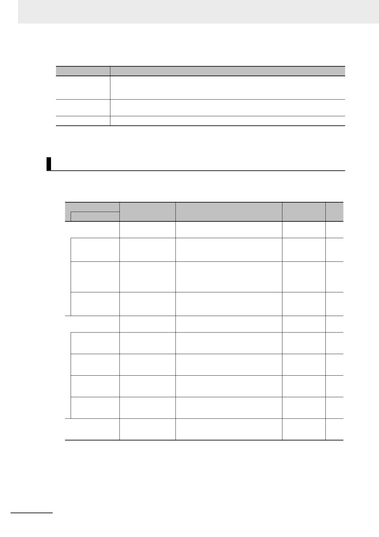
Related System-defined Variables
The system-defined variables that are related to the operation when system-defined variables are used
to verify data are shown below. Refer to A-4 Specifications for Individual System-defined Variables for
details on system-defined variables.
Variable name
Meaning
Function
Data type
R/W
Member name
_Card1BkupCmd*1
SD Memory Card
_sBKUP_CMD
RW
Backup Commands
ExecVefy*1
Execute Verify Flag
Change this variable to TRUE to com-
BOOL
RW
pare the Controller data to a backup file
in the Virtual SD Memory Card.
CancelVefy*1
Cancel Verify Flag
Change this variable to TRUE to cancel
BOOL
RW
comparing the Controller data to a
backup file in the Virtual SD Memory
Card.
DirName*1
Directory Name
Use this variable to specify the directory
STRING(64)
RW
name in the Virtual SD Memory Card for
which to back up data.
_Card1VefySta*1
SD Memory Card
_sVEFY_STA
R
Verify Status
Done*1
Done Flag
TRUE when a verification is completed.
BOOL
R
Active*1
Active Flag
TRUE when a verification is in progress.
BOOL
R
VefyRslt*1
Verify Result Flag
TRUE if the data was the same. FALSE
BOOL
R
if differences were found.
Err*1
Error Flag
TRUE when processing a verification
BOOL
R
ended in an error.
_BackupBusy
Backup Function
TRUE when a backup, restoration, or
BOOL
R
Busy Flag
verification is in progress.
*1. You cannot access these system-defined variables from the user program.
9-16
9 Backup Functions
Additional Information
• Refer to the NA-series Programmable Terminal Software User's Manual (Cat. No. V118) for
information on mapping variables when you connect an NA-series PT to the NY-series Con-
troller.
• Refer to A-7 Registering a Symbol Table on the CX-Designer for the procedure to register these
system-defined variables in the variable table of the CX-Designer when you connect an NS-
series PT to the NY-series Controller.
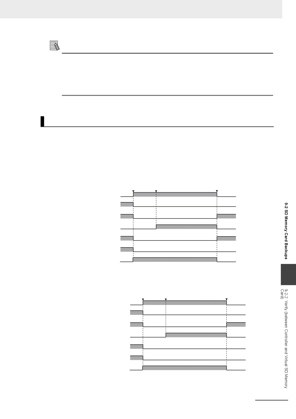
Timing Charts
The operation of the system-defined variables when they are used to verify data is shown below.
In the charts, “pre-execution checks” indicates processing to check whether there is a Virtual SD Mem-
ory Card and other items. The value of _Card1VefySta.Active (Active Flag) changes to TRUE only after
all of the pre-execution checks are cleared and the actual verification is started.
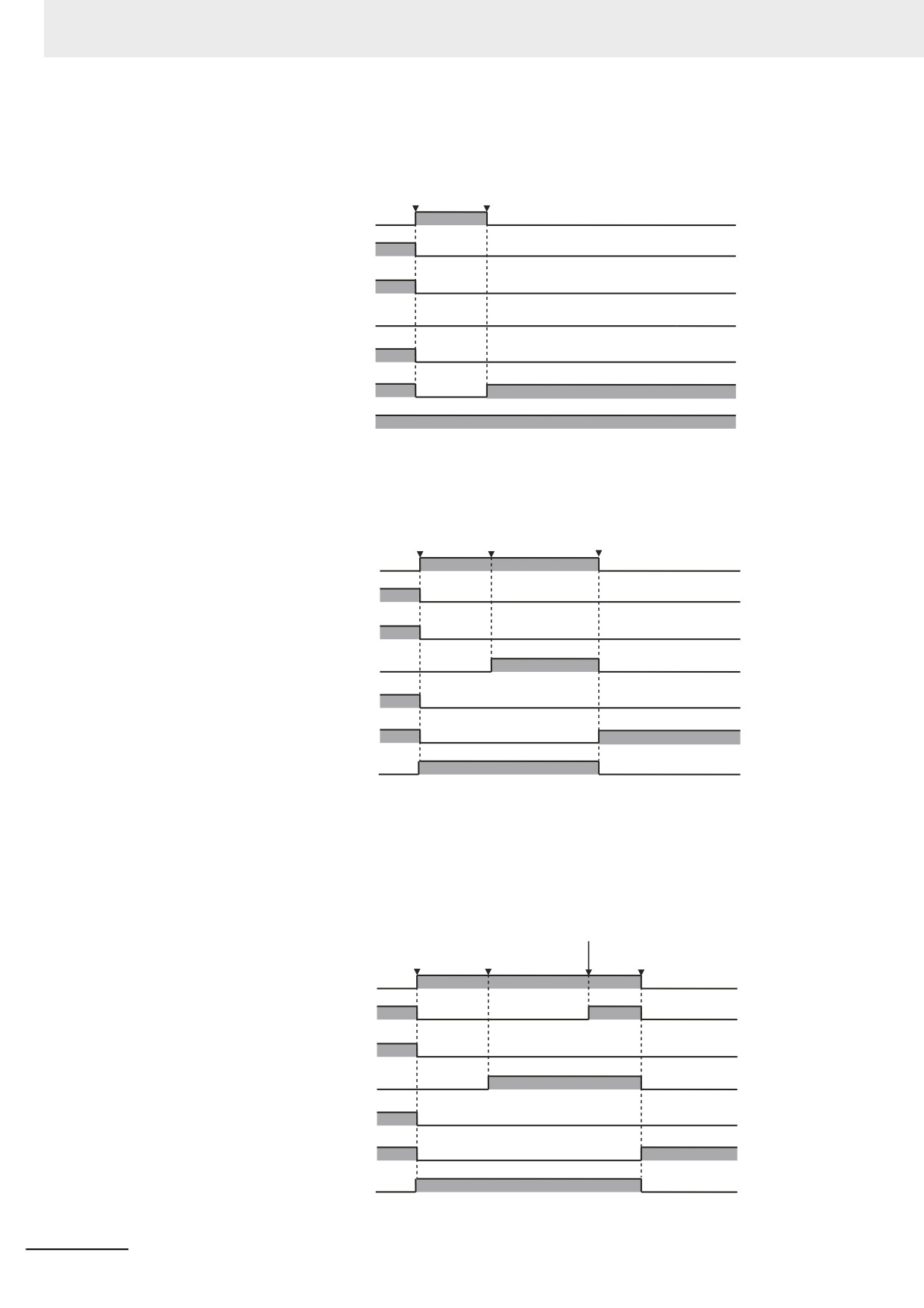
z Normal End with No Differences Found
Verification
Pre-execution
Normal end, no
start command
checks cleared.
differences found
TRUE
_Card1BkupCmd.ExecVefy
FALSE
TRUE
Card1BkupCmd.CancelVefy
FALSE
TRUE
_Card1VefySta.Done
FALSE
TRUE
_Card1VefySta.Active
FALSE
TRUE
_Card1VefySta.Rslt
FALSE
TRUE
_Card1VefySta.Err
FALSE
_BackupBusy
TRUE
FALSE
9
z
Normal End with Differences Found
Verification
Pre-execution
Normal end,
start command
checks cleared.
differences found
TRUE
_Card1BkupCmd.ExecVefy
FALSE
TRUE
_Card1BkupCmd.CancelVefy
FALSE
TRUE
_Card1VefySta.Done
FALSE
TRUE
_Card1VefySta.Active
FALSE
TRUE
_Card1VefySta.Rslt
FALSE
TRUE
_Card1VefySta.Err
FALSE
TRUE
_BackupBusy
FALSE
9-17
9 Backup Functions
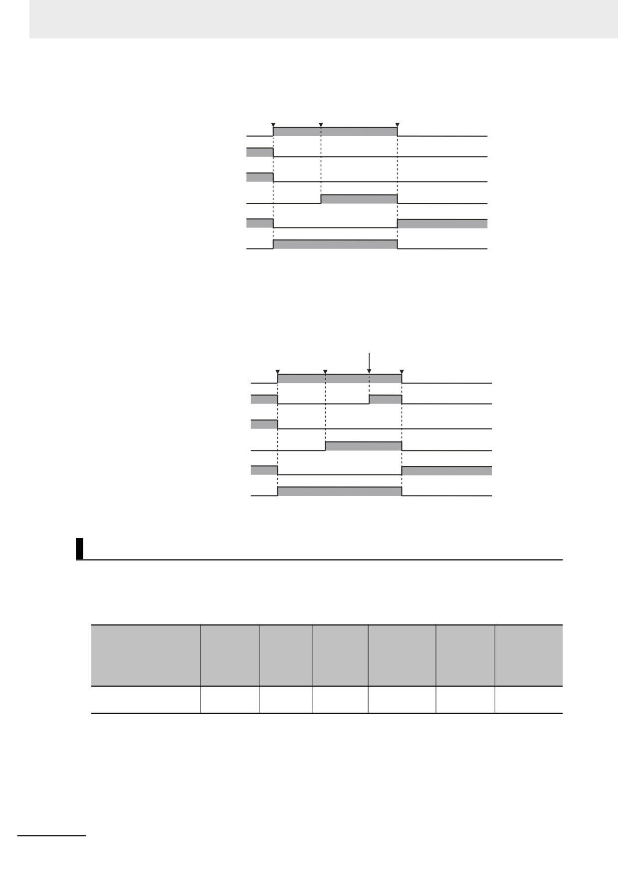
z Operation When the Verification Cannot Start Because Another Backup
Function Is in Progress
Verification
Pre-execution
start command
checks not cleared.
TRUE
_Card1BkupCmd.ExecVefy
FALSE
TRUE
_Card1BkupCmd.CancelVefy
FALSE
TRUE
_Card1VefySta.Done
FALSE
TRUE
_Card1VefySta.Active
FALSE
TRUE
_Card1VefySta.Rslt
FALSE
TRUE
_Card1VefySta.Err
FALSE
TRUE
_BackupBusy
FALSE
z Operation When the Verification Fails After a Normal Start
Verification
Pre-execution
Error occurred
start command
checks cleared.
during verification.
TRUE
_Card1BkupCmd.ExecVefy
FALSE
TRUE
_Card1BkupCmd.CancelVefy
FALSE
TRUE
_Card1VefySta.Done
FALSE
TRUE
_Card1VefySta.Active
FALSE
TRUE
_Card1VefySta.Rslt
FALSE
TRUE
_Card1VefySta.Err
FALSE
_BackupBusy
TRUE
FALSE
z Operation When the Operation Is Canceled While Verification Is in Progress
The time required to stop the verification operation after it is canceled depends on the progress of
the verification operation.
Verification
canceled.
Verification
Pre-execution
Verification stopped
start command
checks cleared.
with an error.
TRUE
_Card1BkupCmd.ExecVefy
FALSE
TRUE
_Card1BkupCmd.CancelVefy
FALSE
TRUE
_Card1VefySta.Done
FALSE
TRUE
_Card1VefySta.Active
FALSE
TRUE
_Card1VefySta.Rslt
FALSE
TRUE
_Card1VefySta.Err
FALSE
TRUE
_BackupBusy
FALSE
9-18