Omron IPC Machine Controller Industrial Panel PC / Industrial Box PC. Software User’s Manual (Industrial PC Platform NY-series) - page 12
7 Checking Operation and Actual Operation
7-1
Overview of Steps in Checking
Operation and Actual Operation
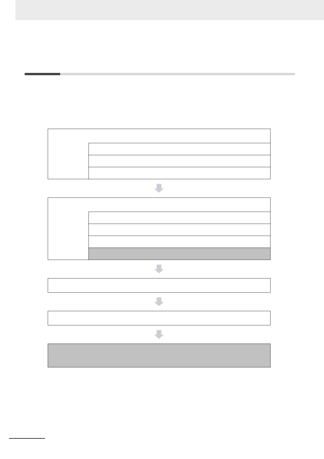
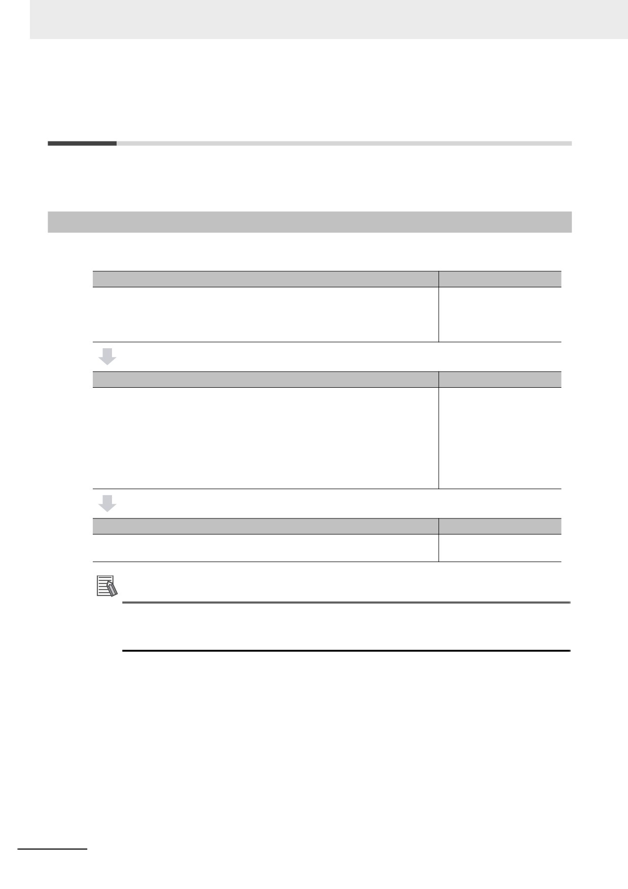
The shaded steps in the overall procedure that is shown below are related to the checking operation
and actual operation. In Step 2-4. Offline Debugging, a simulation is used to check operation without
going online with the Controller. In Step 5. Checking Operation and Starting Operation on the Actual
System, you go online with the Controller to check the operation of the physical Controller. When
checking operation is completed, you start actual operation.
Refer to 1-4 Overall Operating Procedure for the NY-series Controller for the overall procedure.
Step 1. Software Design
Step 1-1 Designing I/O and Processing
Step 1-2 Designing Tasks
Step 1-3 Designing Programs
Step 2. Software Setups and Programming
Step 2-1 Slave and Unit Configurations
Step 2-2 Controller Setup
Step 2-3 Programming
Step 2-4 Offline Debugging
Step 3. Mounting and Setting Hardware
Step 4. Wiring
Step 5. Checking Operation and Starting Operation on the
Actual System
7-2
7 Checking Operation and Actual Operation
7-2
Offline Debugging
This section describes how to use simulation to debug operation offline. You can simulate the operation
of an NY-series Controller on a computer to check the operation of the user program with only the com-
puter. There are also debugging operations that can be used during simulation that are not supported
on the physical Controller. This makes user program development and debugging more efficient.
7-2-1
Features of Simulation
In the following way, simulation is more effective than going online with the Controller to debug opera-
tion.
• You can use breakpoints, step execution, pausing, and other functions to check program logic.
• You can select only specific programs to simulate to check only those programs.
• You can change the simulation execution speed to check operation at a slower speed than for actual
operation.
• You can use debugging programs to manipulate inputs from outside the Controller.
7-2-2
Simulation Execution
You can do the following for simulations.
• Start and stop the Simulator.
• Check the logic of programs.
• Use online debugging functions.
Starting and Stopping the Simulator
7
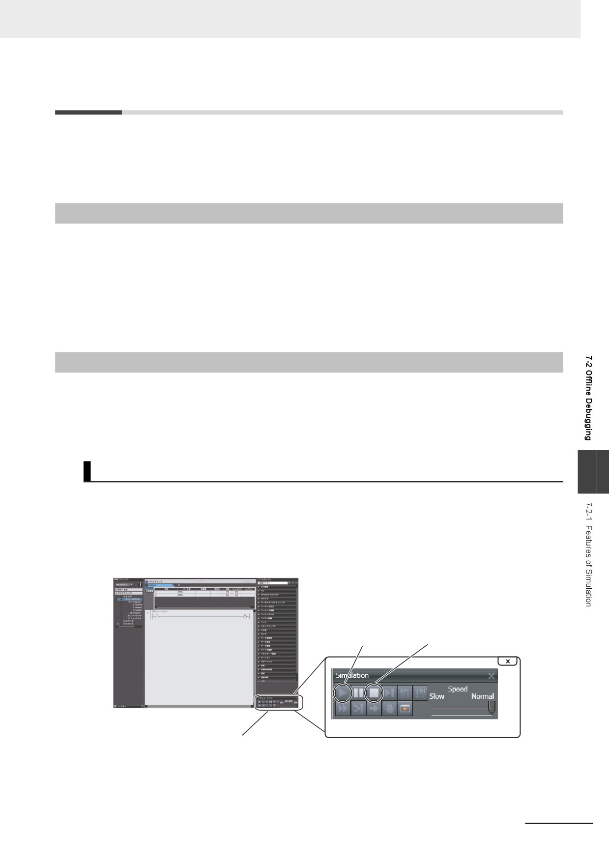
You perform simulations by starting the Simulator from the Simulation Pane of the Sysmac Studio. After
you complete checking operation with the simulation, you stop the Simulator. The following procedure
shows how to start and stop simulations.
1 Select Simulation Pane from the View Menu of the Sysmac Studio.
The Simulation Pane is displayed on the lower right of the window.
Execute Button Stop Button
Simulation Pane
7-3
7 Checking Operation and Actual Operation
2 Click the Execute Button in the Simulation Pane.
The user program is transferred to the Simulator and the simulation starts. When a simulation
starts, the Editors and other parts of the Sysmac Studio window will enter the same state as
when the Sysmac Studio is online with the Controller.
3 After you complete checking operation, click the Stop Button in the Simulation Pane to stop the
Simulator.
Checking the Logic of Programs
You can use simulation debugging to stop the operation of the Simulator or to execute a program one
step at a time to check the validity of the program logic. You can perform the following operations with
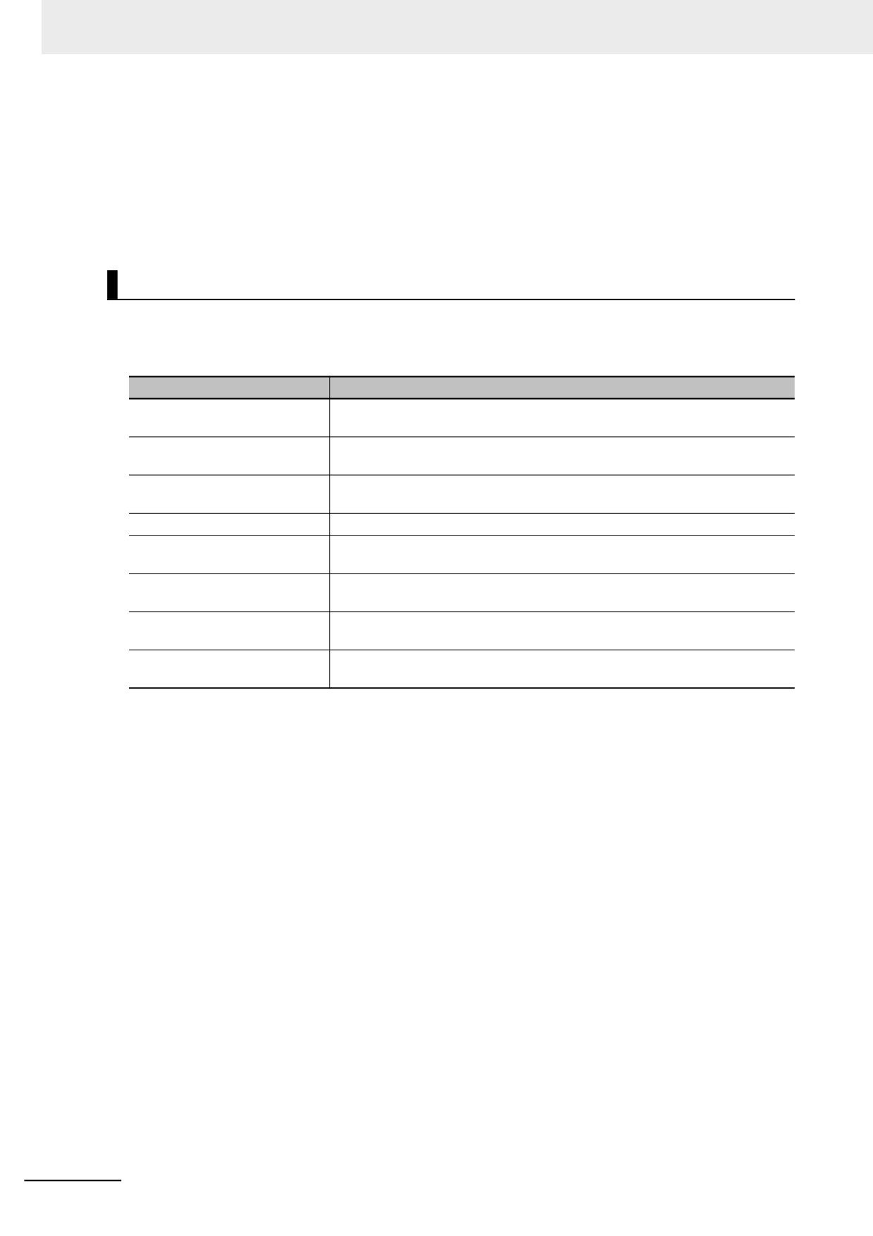
the buttons in the Simulation Pane.
Operation
Description of operation
Breakpoints
Use a breakpoint to specify a location in a program and pause program exe-
cution at that location.
Step execution
Use step execution to execute one line of an ST program or one instruction in
a ladder diagram program and then pause the Simulator.
Continuous step execution
Use continuous step execution to continually perform step execution at a
specified interval.
Pausing
Use pausing to pause execution of the simulation.
Step-in execution
Use step-in execution to perform step execution of source code inside a func-
tion or function block.
Step-out execution
Use step-out execution to execute the current function or function block to the
end.
One-period execution
Use one-period execution to execute the current task for one period. Execu-
tion pauses at the beginning of the program in the next period.
Conditional breakpoints
Use conditional breakpoints to pause the execution of a program at a break-
point when the specified stopping condition is met.
7-4
7 Checking Operation and Actual Operation
Online Debugging Functions
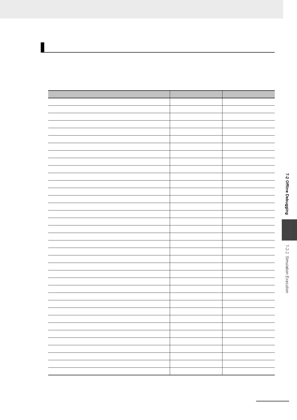
With the Simulator, you can use some of the functions for debugging that are supported when you are
online with the Controller. The following table shows the differences between online debugging with the
Controller or offline debugging with the Simulator. Refer to the Sysmac Studio Version 1 Operation
Manual (Cat. No. W504) for details on the differences in debugging operations for the Controller and for
the Simulator.
Debugging function
Controller
Simulator
Monitoring
Supported.
Supported.
Monitoring in a Watch Tab Page
Supported.
Supported.
Monitoring in the I/O Map
Supported.
Supported.
Differential monitoring
Supported.
Supported.
Controlling BOOL variables
Supported.
Supported.
Forced Refreshing (TRUE/FALSE/Cancel)
Supported.
Supported.
Changing present values of data
Supported.
Supported.
Clearing all memory
Supported.
Not supported.
Cross-reference pop-ups
Supported.
Supported.
Online editing
Supported.
Supported.
Monitoring Controller status
Supported.
Not supported.
Monitoring task execution status
Supported.
Supported.
Monitoring axis status (MC Monitor Table)
Supported.
Supported.
Changing the operating mode
Supported.
Not supported.
Resetting the Controller
Supported.
Not supported.
Data tracing
Supported.
Supported.
Setting triggers
Supported.
Supported.
Setting variables to sample
Supported.
Supported.
7
Starting and stopping tracing
Supported.
Supported.
Displaying trace results
Supported.
Supported.
Exporting trace results
Supported.
Supported.
Creating 3D equipment models
Supported.
Supported.
Displaying digital and analog charts
Supported.
Supported.
Displaying 3D axis paths
Supported.
Supported.
Monitoring task execution times
Supported.
Not supported.
Debugging with program simulations
Not supported.
Supported.
Setting simulation programs
Not supported.
Supported.
Changing the simulation speed
Not supported.
Supported.
Setting breakpoints
Not supported.
Supported.
Step execution
Not supported.
Supported.
Troubleshooting
Supported.
Supported.
Monitoring error information
Supported.
Supported.
Displaying error logs
Supported.
Supported.
Setting event tables
Supported.
Supported.
Monitoring user memory usage
Supported.
Supported.
Clock Information Settings
Supported.
Not supported.
Releasing access rights
Supported.
Not supported.
7-5
7 Checking Operation and Actual Operation
7-2-3
Setting Up Simulations
You set the following for simulations.
• Setting simulation programs
• Setting debug programs
• Setting the simulation speed
Setting Simulation Programs
You can set the task or programs to simulate. You can choose to simulate some or all of the programs
in the user program. The following procedure shows how to set the simulation programs.
1 Display the Simulation Pane.
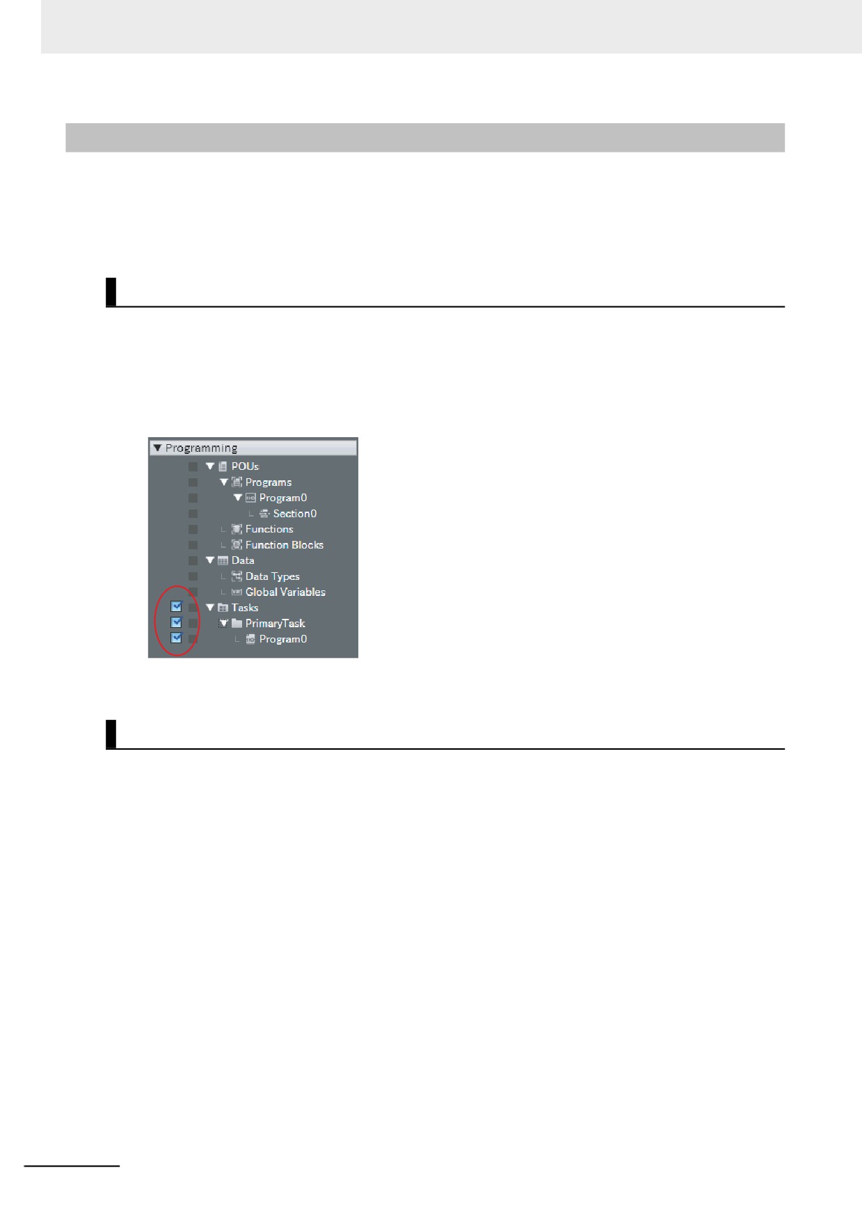
Check boxes are displayed to the left of the programs that are listed under Tasks in the Multiv-
iew Explorer project to designate programs for simulation.
2 Select the check boxes for the tasks or programs to simulate.
Setting Debug Programs
A debugging program is used to check operation with offline debugging. The debugging program con-
tains instructions to perform virtual input processing on inputs received from outside of the Controller,
force user-defined errors, and perform other such debugging tasks. You can execute debugging pro-
grams only on the Simulator.
The following procedure shows how to create debugging programs.
1 Right-click Programs under Programming − POU in the Multiview Explorer and select Add for
Debugging − Multipart Ladder or Add for Debugging − Structured Text from the menu.
A debug program is created.
2 Enter the test program code into the debugging program that you just created.
3 Assign the debugging program to a task.
You can also change a normal program that is already completed into a debug program in the same
way.
1 Right-click a program under Programming − POU − Programs in the Multiview Explorer and
select Settings For Debugging − Enable.
7-6
7 Checking Operation and Actual Operation
Setting the Simulation Speed
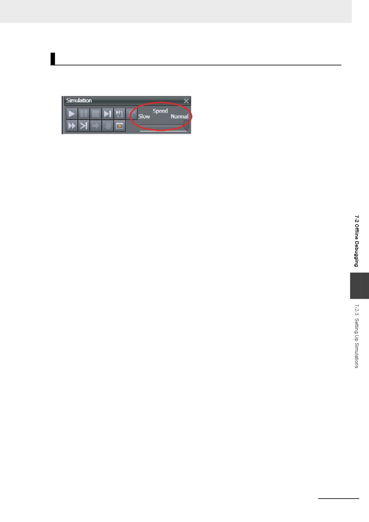
You can use the Simulation Speed Slider in the Simulation Pane to change the simulation speed from
0.1x to 1x. You can change simulation speed while a simulation is in progress or when it is stopped.
Use this to display the execution of the Simulator more slowly than for actual operation.
7
7-7
7 Checking Operation and Actual Operation
7-3
Checking Operation on the Actual
System and Actual Operation
This section describes the procedures from checking operation on the actual system to starting actual
operation.
7-3-1
Procedures
The procedures from checking operation on the actual system to starting actual operation are given
below.
Step 1. Going Online from the Sysmac Studio and Downloading the Project
Reference
1. Turn ON the power supply to the Controller.
Sysmac Studio Version 1
2. Place the Sysmac Studio online with the Controller.
Operation Manual (Cat.
No. W504)
3. Download the project (i.e., the user program, Unit configuration, and other
settings) from the Sysmac Studio.
Step 2. Checking Operation on the Controller
Reference
1. In PROGRAM mode, check the I/O wiring by performing forced-refreshing
7-3-3 Checking I/O Wiring
with user-specified values from the I/O Map or Ladder Editor.
NY-series Industrial Panel
2. For motion control, use the MC Test Run operations to perform the following:
PC / Industrial Box PC
check the wiring, jog to check the motor rotation directions, perform relative
Motion Control User's
positioning to check the travel distances (e.g., for electronic gear settings),
Manual (Cat. No. W559)
and check homing operation.
7-3-5 Checking the Opera-
3. Change the Controller to RUN mode and check the operation of the user pro-
tion of the User Program
gram.
Step 3. Starting Actual Controller Operation
Reference
1. Confirm that operation is performed as designed and then start actual opera-
---
tion.
Additional Information
Use the synchronization function to download the project from the Sysmac Studio to the Control-
ler. Refer to the Sysmac Studio Version 1 Operation Manual (Cat. No. W504) for information on
the synchronization function.
7-8
7 Checking Operation and Actual Operation
7-3-2
Downloading the Project
Use the following procedure to download the project from the Sysmac Studio to the physical Controller.
1 Go online with the Controller, and then select Synchronization from the Controller Menu.
The data on the computer and the data in the physical Controller are compared automatically.
2 Click the Transfer to Controller Button.
7-3-3
Checking I/O Wiring
Check the I/O wiring by using forced refreshing from the Watch Tab Page of the Sysmac Studio. You
can write values to I/O for Units or slaves to check the results to test the I/O wiring. Refer to 8-4-1
Forced Refreshing for information on forced refreshing.
7-3-4
MC Test Run
The MC Test Run function is used mainly to perform the following operations from the Sysmac Studio
without a user program.
• Checking wiring: You can monitor Servo Drive connector I/O signals and Servo Drive status.
• Checking the operation and direction of the motor: You can turn ON the Servo and jog axes.
• Checking electronic gear settings: You can perform relative positioning, and check and change travel
distances.
• Checking homing: You can check the homing operation.
Connect online to the Controller from the Sysmac Studio and perform the MC Test Run on the MC Test
Run Tab Page.
For details, refer to the NY-series Industrial Panel PC / Industrial Box PC Motion Control User's Manual
7
(Cat. No. W559).
Use the following procedure.
1 After you complete the necessary wiring, connect the Sysmac Studio online to the Controller.
2 Create axes, assign the axes, and set the following axis parameters.
Axis parameter settings required for an MC Test Run: Unit of Display, Command Pulses Per
Motor Rotation, Travel Distance Per Motor Rotation, Maximum Velocity, Maximum Jog Velocity,
Maximum Acceleration Rate, Maximum Deceleration Rate, Software Limit Function Selection,
Software Limits, and Count Mode
3 Open the MC Test Run Tab Page and perform the following.
Example:
• Monitoring and checking wiring
• Jogging to check the direction of the motor
• Check travel distances for relative positioning (electronic gear settings).
• Confirming the homing operation
7-9

7 Checking Operation and Actual Operation
7-3-5
Checking the Operation of the User Program
To check the operation of the user program on the actual system, change the operating mode of the
Controller to RUN mode. You can use the following to check operation.
• Checking the operation of the user program
• Correcting the user program with online editing
• Checking the operation of the user program with data tracing
Checking the Operation of the User Program
You can perform the following to check the operation of the user program.
1 Monitor the execution status of the user program.
2 Check the operation by changing the status of program inputs and program outputs, and the
values of variables.
z Monitoring the Execution Status of the User Program
You can monitor the TRUE/FALSE status of program inputs and outputs and the present values of
variables in the Controller. You can monitor the status on the Ladder Editor, Watch Tab Page, or I/O
Map of the Sysmac Studio.
z Checking the Operation by Changing the Status of Program Inputs and
Program Outputs, and the Values of Variables
You can change the TRUE/FALSE status of program inputs and outputs and the present values of
variables in the user program to see if the user program operates as designed. Use forced refresh-
ing to change the status of program inputs and program outputs. Use one of the methods to change
the present values of variables. Refer to 8-4-1 Forced Refreshing and 8-4-2 Changing Present Val-
ues for details.
Correcting the User Program with Online Editing
You can use online editing to correct a user program that you determined needs to be corrected while
checking operation. You can use online editing to change a user program without stopping the opera-
tion of the Controller. Refer to 8-4-3 Online Editing for details.
Checking Operation with Data Tracing
You can use data tracing to check when program inputs and program outputs are changed to TRUE or
FALSE and to check changes in the values of variables. Refer to 8-4-4 Data Tracing for details.
7-3-6
Starting Actual Operation
Change the operating mode to RUN mode to start actual operation. Check the user program, data, and
parameter settings sufficiently for proper execution before you use them for actual operation.
7-10

Controller Functions
This section describes the functionality provided by the NY-series Controller.
8-1
Data Management, Clock, and Operating Functions
8-3
8-1-1
Clearing All Memory
8-3
8-1-2
Clock
8-3
8-2
SD Memory Card Operations
8-6
8-2-1
SD Memory Card Operations
8-6
8-2-2
Setting Shared Folders and Virtual SD Memory Cards
8-7
8-2-3
Recognizing and Canceling Recognitions of Virtual SD Memory Cards
8-7
8-2-4
Specifications of Shared Folders and Files for Windows
8-10
8-2-5
SD Memory Card Instructions
8-12
8-2-6
FTP Client Communications Instructions
8-12
8-2-7
FTP Server
8-13
8-2-8
File Operations from the Sysmac Studio
8-13
8-2-9
List of System-defined Variables Related to SD Memory Cards
8-14
8
8-2-10
Exclusive Control of File Access in Virtual SD Memory Cards
8-15
8-3
Security
8-16
8-3-1
Authentication of User Program Execution IDs
8-17
8-3-2
User Program Transfer with No Restoration Information
8-20
8-3-3
Overall Project File Protection
8-21
8-3-4
Data Protection
8-22
8-3-5
Operation Authority Verification
8-24
8-3-6
CPU Unit Write Protection
8-26
8-3-7
CPU Unit Names and Serial IDs
8-27
8-4
Debugging
8-29
8-4-1
Forced Refreshing
8-29
8-4-2
Changing Present Values
8-33
8-4-3
Online Editing
8-35
8-4-4
Data Tracing
8-37
8-4-5
Differential Monitoring
8-43
8-1
8 Controller Functions
8-5
Event Logs
8-49
8-5-1
Introduction
8-49
8-5-2
Detailed Information on Event Logs
8-50
8-5-3
Controller Events (Controller Errors and Information)
8-55
8-5-4
User-defined Events (User-defined Errors and Information)
8-56
8-6
Changing Event Levels
8-63
8-6-1
Applications of Changing Event Levels
8-63
8-6-2
Events for Which the Event Level Can Be Changed
8-63
8-6-3
Procedure to Change an Event Level
8-64
8-2
8 Controller Functions
8-1
Data Management, Clock, and
Operating Functions
This section describes the data management, clock, and operating functions.
8-1-1
Clearing All Memory
You can initialize the user program, Controller Configurations and Setup, variables, and absolute
encoder home offsets in the NY-series Controller to the defaults from the Sysmac Studio. This is called
the Clear All Memory operation.
Precautions for Correct Use
• The Clear All Memory operation can be performed only in PROGRAM mode.
• You cannot execute the Clear All Memory operation when write protection of the CPU Unit is
set in the security functions.
• Do not turn OFF the power supply to the NY-series Controller during the Clear All Memory
operation.
After you clear the memory, the NY-series Controller operates in the same way as immediately after you
create the system configuration with the NY-series Controller in the factory default condition.
z Operations from the Sysmac Studio
Connect the Sysmac Studio to the NY-series Controller online, and select Clear All Memory from
the Controller Menu.
Refer to the Sysmac Studio Version 1 Operation Manual (Cat. No. W504) for specific procedures.
8
8-1-2
Clock
Of the built-in clocks in the NY-series Industrial PCs, this section describes a clock in the Controller.
Introduction
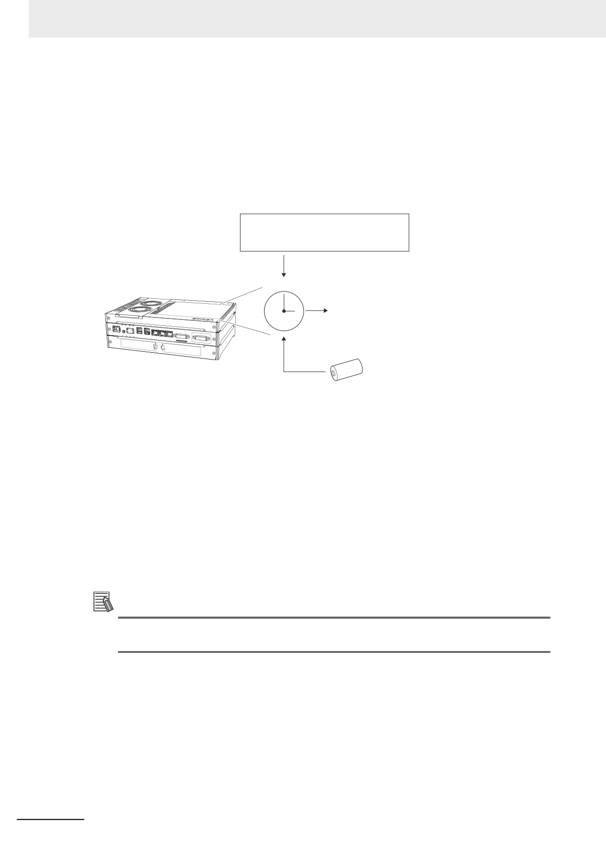
In the NY-series Industrial PC, there is a clock and time zone in either Windows or the Controller that is
embedded in the Real-Time OS.
The clock data of the clock in Windows is the master clock and the clock data of the clock in the Con-
troller is synchronized with the clock in Windows. Therefore, you can change the clock data of the clock
in Windows, but you cannot change the clock data of the clock in the Controller.
If you cannot get the clock data from Windows due to a shutdown on Windows only or other reasons,
the clock data of the clock in the Controller is not synchronized with the clock in Windows. The clock in
the Controller continues to operate even while it is not synchronized with the clock in Windows.
When you restart Windows to get the clock data from Windows, the clock data of the clock in the Con-
troller will be synchronized with the clock in Windows again.
The clock data of the clock in the Controller is used for event logs and for the time and date of files that
are created on the Virtual SD Memory Card.
8-3
8 Controller Functions
The time zone in the Controller depends on the time zone in Windows.
You cannot separately set the time zone in Windows and the time zone in the Controller.
The following functions are supported for the clock in the Controller.
• Reading the clock from the Sysmac Studio (Writing is not possible.)
• Reading the clock from instructions (Writing is not possible.)
• Reading the clock from system-defined variables (Writing is not possible.)
• Reading the clock from the Sysmac Studio
• Reading the clock with instructions
Controller
Clock data
• Event logs
• Time and date of files that are
created on Virtual SD Memory Card
Battery backup
Battery
CJ1W-BAT01
z Clock Data Range for Controller
•
2000-01-01 to 2099-12-31 (January 1, 2000 to December 31, 2099).
z Setting the Time Zone and the Local Time
The time zone and local time in the clock data in the Controller depend on the settings in Windows.
Therefor, before you use the Controller for the first time, set the time zone and local time in the clock
data in Windows.
The clock data that is read by the EtherCAT slaves from the Controller and the clock data that is set
are the local times in the time zone.
Additional Information
When a Battery is not mounted or when the Battery voltage is low, the time zone setting is
retained, but the clock data is not retained and will not be correct.
8-4
8 Controller Functions
Reading the Clock Data
If the clock data is incorrect, the incorrect value is read.
z Reading the Clock Data from Instructions (Writing Is Not Possible)
You can use the GetTime instruction to read the clock data from the user program.
z Reading the Clock from System-defined Variables (Writing Is Not Possible)
You can use the following system-defined variable to read the clock data.
_CurrentTime (System Time)
z Sysmac Studio Procedure (Writing Is Not Possible)
You can select Controller Clock from the Controller Menu of the Sysmac Studio to display the clock
data.
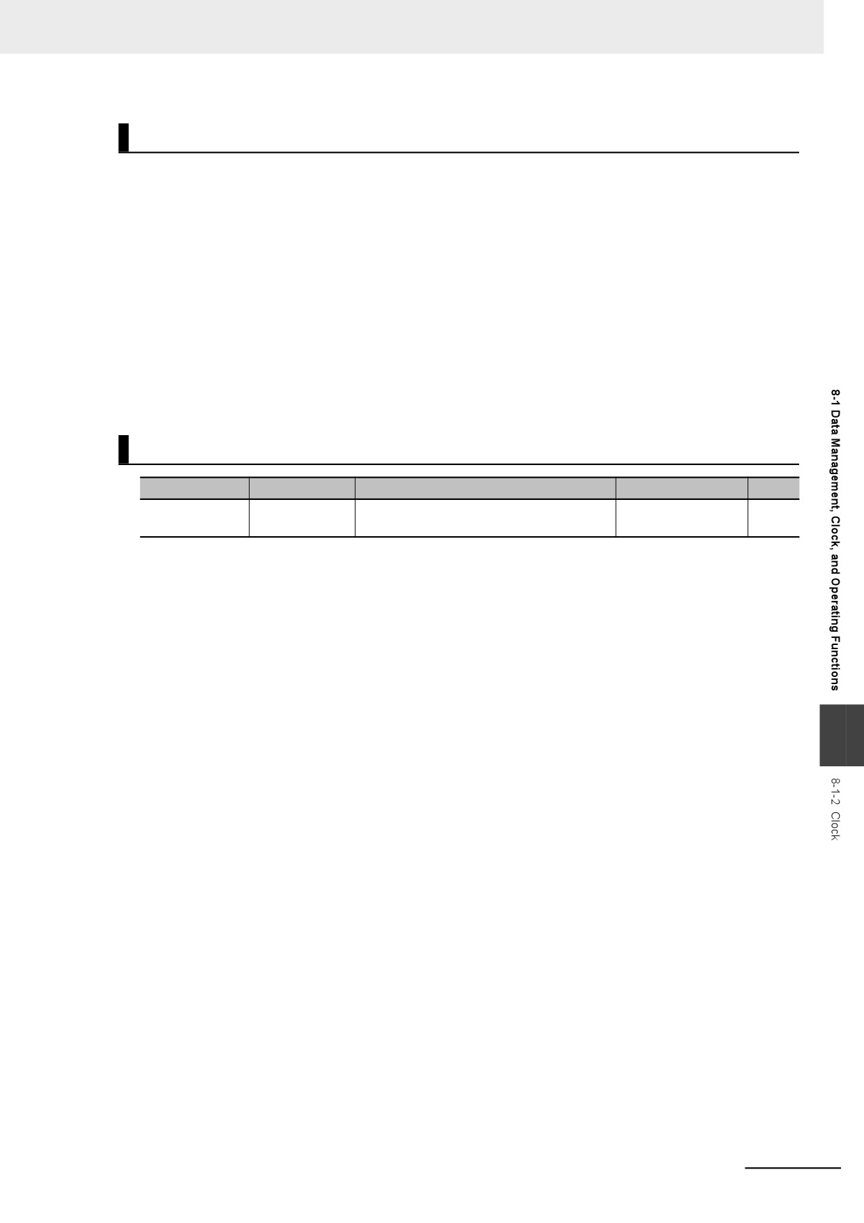
Related System-defined Variables
Variable name
Meaning
Description
Data type
R/W
_CurrentTime
System Time
This variable contains the Controller's inter-
DATE_AND_TIME
R
nal clock data.
8
8-5
8 Controller Functions
8-2
SD Memory Card Operations
This section describes the functions that you can use for SD Memory Cards.
In the NY-series Controller, a shared folder with Windows is handled as a Virtual SD Memory Card. In
this manual, only the SD Memory Card is sometimes given without "virtual".
8-2-1
SD Memory Card Operations
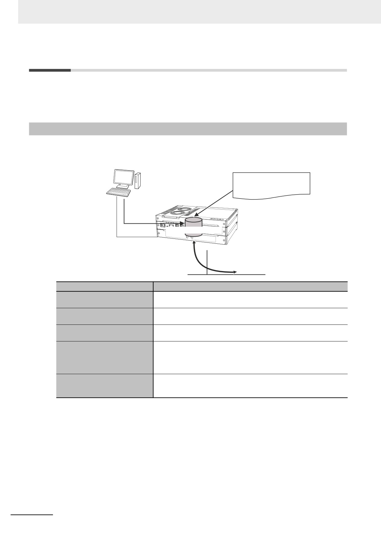
The NY-series Controller supports the following functions for SD Memory Cards.
Sysmac Studio
SD Memory Card instructions
Controller
Creating/reading files
Virtual SD Memory Card
from Sysmac Studio
FTP client communications
FTP server
instructions
Function
Introduction
You can access Virtual SD Memory Cards from instructions in the user pro-
SD Memory Card instructions
gram.
FTP client communications
You can use these instructions to transfer files via FTP from the Controller
instructions
to computers or Controllers at Ethernet nodes.
You can use FTP commands from an FTP client on the Intranet to read
FTP server
and write large files in the Virtual SD Memory Card through EtherNet/IP.
You can perform file operations from the Sysmac Studio for the Virtual SD
File operations from the Sysmac
Memory Card in the Controller.
Studio*1
You can perform file operations for Controller files in the Virtual SD Mem-
ory Card and save standard document files on the computer.
You use the Virtual SD Memory Card in the Controller to backup, restore,
SD Memory Card backup
and verify user programs and data in the Controller. Refer to 9-2 SD Mem-
ory Card Backups for details.
*1
For an NY-series Controller, you cannot initialize the SD Memory Card or change the folder and file attributes
on the SD Memory Card.
The volume level of the SD Memory Card is not displayed on the Status Bar in the SD Memory Card Window of
the Sysmac Studio because the Virtual SD Memory Card is using a shared folder.
8-6
8 Controller Functions
8-2-2
Setting Shared Folders and Virtual SD Memory Cards
This section describes the settings for using the SD Memory Card operations in the NY-series Control-
ler.
Setting Shared Folders
You need to set the shared folder in Windows before you make the settings for the Virtual SD Memory
Card.
In the default setting of Windows in an NY-series Industrial PC, D:\OMRON-NY\VirtualSDCard is set as
the shared folder for a Virtual SD Memory Card.
Refer to the NY-series Industrial Panel PC / Industrial Box PC Setup User's Manual (Cat. No. W568) for
details on setting the shared folder.
Setting Virtual SD Memory Cards
Make the settings for the Virtual SD Memory Card in the Controller Setup of the Sysmac Studio.
Refer to Virtual SD Memory Card Settings on page 4-5 for details on the Virtual SD Memory Card Set-
ting.
Additional Information
You can also make the settings for the Virtual SD Memory Card with the Industrial PC Support
Utility instead of the Sysmac Studio.
Refer to the NY-series Industrial Panel PC / Industrial Box PC Setup User's Manual (Cat. No.
W568) for the procedure to set the Virtual SD Memory Card with the Industrial PC Support Utility.
8-2-3
Recognizing and Canceling Recognitions of Virtual SD Memory Cards
This section describes how to recognize and cancel the recognition of the Virtual SD Memory Card.
8
Recognizing Virtual SD Memory Cards
The Virtual SD Memory Card is recognized if the following operations are performed.
When the Virtual SD Memory Card is recognized, the _Card1Ready (SD Memory Card Ready Flag)
system-defined variable changes to TRUE.
• Starting the NY-series Controller
• Downloading
• Restoring data
• Changing the settings of the Virtual SD Memory Card with the Industrial PC Support Utility
• Checking the recognition of the Virtual SD Memory Card with the Industrial PC Support Utility
The Virtual SD Memory Card cannot be recognized in the following cases.
• Windows is stopped.
• The file sharing service of Windows is stopped.
• The settings of the Virtual SD Memory Card are invalid.
8-7
8 Controller Functions
Canceling Recognition of Virtual SD Memory Cards
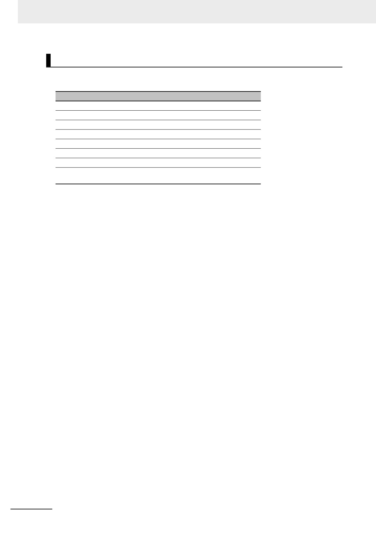
The recognition of the Virtual SD Memory Card is canceled due to the reasons given in the following
table.
Cause
Windows was shut down or restarted.
The file sharing service of Windows was stopped or disabled.
The computer name on Windows was changed.
The IP address of the internal port for Windows was changed.
Sharing the shared folder was canceled.
The shared folder was deleted.
The access right of the shared folder was changed.
The IP address of the internal communications port for Controller was changed
to a different IP address of the internal communications port for Windows.
When the recognition of the Virtual SD Memory Card is canceled, the _Card1Ready (SD Memory Card
Ready Flag) system-defined variable changes to FALSE and a Shared Folder Recognition Cancel
Completed event will occur.
The file access that is in progress is failed if the recognition is canceled while accessing the Virtual SD
Memory Card.
The operations after canceling are different depend on the causes that are canceled.
z If the Cause Is Sharing the Shared Folder Was Canceled or the Shared Folder
Was Deleted
If the cause that the recognition of the Virtual SD Memory Card is canceled is sharing the shared
folder was canceled or the shared folder was deleted, the Virtual SD Memory Card is not recognized
again only by re-sharing the shared folder in Windows.
The Virtual SD Memory Card is recognized again by either of the following methods.
• Re-share the shared folder and execute Check recognition from the Industrial PC Support Utility.
However, if the file is open with an instruction in the SD Memory Card instructions before the shar-
ing is canceled, you need to close the opened file.
• Re-share the shared folder and the idle session time (15 minutes for the default) for Windows is
elapsed from the sharing was canceled.
z If the Cause Is One Other Than Sharing the Shared Folder Was Canceled or
the Shared Folder Was Deleted
The Virtual SD Memory Card is automatically recognized when the cause is removed and the nor-
mal status is restored.
If the Virtual SD Memory Card is recognized, when downloading, performing restore operation, clearing
all memory, or transferring the settings from the Industrial Support Utility, the followings will happen.
• The recognition of the Virtual SD Memory Card is canceled.
• The _Card1Ready (SD Memory Card Ready Flag) system-defined variable changes to FALSE.
• A Shared Folder Recognition Cancel Completed event occurs.
However, while accessing the Virtual SD Memory Card, the recognition of the Virtual SD Memory Card
is not canceled and a Shared Folder Recognition Cancel Failed event occurs.
8-8
8 Controller Functions
Precautions for Correct Use
Do not turn OFF the power supply to the Industrial PC while accessing the Virtual SD Memory
Card.
The files may be corrupted if the power supply is turned OFF.
The _Card1PowerFail (SD Memory Card Power Interruption Flag) system-defined variable
changes to TRUE at next time you start operation.
8
8-9
8 Controller Functions
8-2-4
Specifications of Shared Folders and Files for Windows
This section describes the specifications of the shared folder that is used as a Virtual SD Memory Card
and the file specifications.
Specifications of Shared Folders
The following describes the specifications of the shared folder that is set on Windows.
z Settable Storage
You can use the shared folder that is set in the HDD or SSD built in the industrial PC as a Virtual SD
Memory Card.
The shared folder that is not set in the HDD or SSD built in the industrial PC cannot be guaranteed
as a Virtual SD Memory Card.
z Restrictions on Capacity of Shared Folder
Use the shared folder as a Virtual SD Memory Card within the capacity of 16 GB(*).
If the file capacity in the shared folder exceeds the restricted capacity, correct operation may not be
possible.
* For a Controller with unit version 1.19 or earlier, use the shared folder within the capacity of 4 GB.
z File System
You can only use the NTFS file system as a Virtual SD Memory Card.
Folder and File Specifications
z Character Restrictions
Object
Multibyte
Maximum
Case sen-
named by
Usable characters
Reserved words
character
size (without
sitivity
user
compatibility
NULL)
Directory
0 to 9, A to Z, and a to
CON, PRN, AUX,
Not sup-
Case insen-
65 bytes
name
z, as well as $ % ’ - _
CLOCK$, NUL,
ported.*1
sitive
@ ! ‘ ( ) ~= # & + ^ [ ] {
COM0, COM1,
File name
65 bytes
} , . ;
COM2, COM3,
COM4, COM5,
COM6, COM7,
COM8, COM9,
LPT0, LPT1, LPT2,
LPT3, LPT4, LPT5,
LPT6, LPT7, LPT8,
LPT9
*1
Even if the computer supports multibyte characters (e.g., for Japanese), you cannot use them in the Controller.
Precautions for Correct Use
If unusable characters are included in the directory name or file name, the Controller cannot be
correctly recognized. Files may not be identified in instructions, in the SD Memory Card Window
of the Sysmac Studio or in the FTP server.
8-10
8 Controller Functions
z Subdirectory Levels
You can create up to 5 levels (example: f1/f2/f3/f4/f5/abc.txt)
You can create up to 5 levels.
Example) If VirtualSDCard is used as a name of the shared folder
VirtualSDCard\f1\f2\f3\f4\f5\abc.txt
z Restrictions on Number of Stored Files
Use the number of stored files on a Virtual SD Memory Card which is less than the value given in the
following table. If the number of stored files exceeds the value given in the following table, correct
operation may not be possible.
Directory level
Number of stored files
Root directory
65,535
Subdirectory
65,534
z Maximum Size of One File
The maximum size of any one file is 2,147,483,647 bytes (2 GB −1 byte).
8
8-11
8 Controller Functions
8-2-5
SD Memory Card Instructions
You can perform various operations on the Virtual SD Memory Card by using the following instructions.
Instruction name
Instruction
Description
The FileReadVar instruction reads the contents of a binary file on the Virtual
Read Variable
FileReadVar
SD Memory Card and writes it to the specified variable. You can specify
from File
array and structure variables.
The FileWriteVar instruction writes the value of a specified variable to a
Write Variable to
binary file in the Virtual SD Memory Card. You can specify array and struc-
FileWriteVar
File
ture variables. If the directory specified for the file name does not exist, it is
created.
Open File
FileOpen
The FileOpen instruction opens the specified file.
Close File
FileClose
The FileClose instruction closes the specified file.
Seek File
FileSeek
The FileSeek instruction sets a file position indicator in the specified file.
Read File
FileRead
The FileRead instruction reads the data from the specified file.
Write File
FileWrite
The FileWrite instruction writes data to the specified file.
The FileGets instruction reads a text string of one line from the specified
Get Text String
FileGets
file.
Put Text String
FilePuts
The FilePuts instruction writes a text string of one line to the specified file.
The FileRemove instruction deletes the specified file from the Virtual SD
Delete File
FileRemove
Memory Card.
Change File
The FileRename instruction changes the name of the specified file or direc-
FileRename
Name
tory.
Copy File
FileCopy
The FileCopy instruction copies the specified file to a different file.
The DirCreate instruction creates a directory in the Virtual SD Memory
Create Directory
DirCreate
Card.
The DirRemove instruction deletes a directory from the Virtual SD Memory
Delete Directory
DirRemove
Card.
8-2-6
FTP Client Communications Instructions
FTP client communications instructions are used to transfer files via FTP from an NY-series Controller
to computers or Controllers at Ethernet nodes.
The files on the Virtual SD Memory Card are read and written when the following instructions are exe-
cuted.
Instruction name
Instruction
Description
The FTPPutFile instruction uploads one or more files in the FTP
Put File onto FTP Server
FTPPutFile
client’s Virtual SD Memory Card to the FTP server.
The FTPGetFile instruction downloads one or more files from the
Get File from FTP Server
FTPGetFile
FTP server to the FTP client’s Virtual SD Memory Card.
8-12
8 Controller Functions
8-2-7
FTP Server
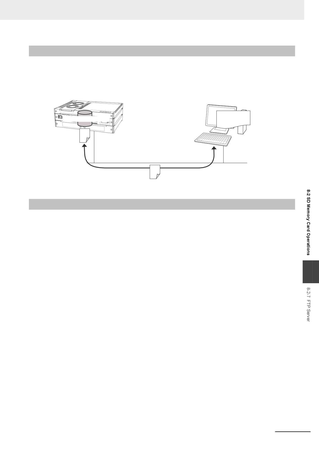
You can read and write files on the Virtual SD Memory Card via EtherNet/IP by sending FTP com-
mands to the built-in EtherNet/IP port from an FTP client.
Refer to the NY-series Industrial Panel PC / Industrial Box PC Built-in EtherNet/IP Port User's Manual
(Cat. No. W563) for details.
Controller
FTP Client
FTP
Virtual SD Memory Card
commands
Built-in EtherNet/IP port: FTP server
EtherNet/IP
File transfers
8-2-8
File Operations from the Sysmac Studio
You can perform file operations from the Sysmac Studio for the Virtual SD Memory Card in the Controller.
In addition to Controller files, you can also store document files or other files on the Virtual SD Memory
Card.
8
8-13
8 Controller Functions
8-2-9
List of System-defined Variables Related to SD Memory Cards
The following system-defined variables show the status of the SD Memory Card.
Variable name
Meaning
Description
Data type
_Card1Ready
SD Memory Card
TRUE when the Virtual SD Memory Card is recognized in
BOOL
Ready Flag
an NY-series Controller. It is FALSE when a Virtual SD
Memory Card is not recognized.
TRUE: The Card can be used.
FALSE: The Card cannot be used.
_Card1Protect
SD Memory Card
The NY-series Controller does not use this variable.
BOOL
Write Protected
The value is always FALSE.
Flag
_Card1Err
SD Memory Card
The NY-series Controller does not use this variable.
BOOL
Error Flag
The value is always FALSE.
_Card1Access
SD Memory Card
The NY-series Controller does not use this variable.
BOOL
Access Flag
The value is always FALSE.
_Card1Deterio-
SD Memory Card
The NY-series Controller does not use this variable.
BOOL
rated
Life Warning Flag
The value is always FALSE.
_Card1PowerFail
SD Memory Card
TRUE when the power supply to the Controller was inter-
BOOL
Power Interrup-
rupted during access to the Virtual SD Memory Card.
tion Flag*1
TRUE: Power was interrupted during Virtual SD Memory
Card access.
FALSE: Operation is normal.
_Card1Capacity
SD Memory Card
Show the total capacity of the Virtual SD Memory Card.
UDINT
Storage Capacity
The unit of capacity is MiB (1 MiB=1,048,576 bytes).
The value is updated every 60 seconds.
If the Virtual SD Memory Card is disabled, the value is “0”.
_Card1Used
SD Memory Card
Show the usage of the Virtual SD Memory Card.
UDINT
Storage Usage
The unit of capacity is MiB (1 MiB=1,048,576 bytes).
The value is updated every 60 seconds.
If the Virtual SD Memory Card is disabled, the value is “0”.
*1
Precautions When Using the SD Memory Card Power Interruption Flag (_Card1PowerFail)
If the SD Memory Card Power Interruption Flag is TRUE, check to see if the correct file is in the Virtual SD
Memory Card and to see if the Virtual SD Memory Card operates properly. If the correct file is missing or the
Virtual SD Memory Card does not operate properly, download the correct file to the Virtual SD Memory Card
again. Cycle the power supply to the Controller or reset the Controller, and then see if the Virtual SD Memory
Card operates properly. When you are finished, change the SD Memory Card Power Interruption Flag to
FALSE. (_Card1PowerFail does not change to FALSE automatically.)
Note Refer to 9-2 SD Memory Card Backups for the system-defined variables that are used with the SD Memory
Card backup function.
8-14
8 Controller Functions
8-2-10
Exclusive Control of File Access in Virtual SD Memory Cards
Access to files on the Virtual SD Memory Card is possible with the following methods.
(1) FTP server
(2) SD Memory Card instructions
(3) FTP client communications instructions
(4) File operations from the Sysmac Studio
However, if the same file on the Virtual SD Memory Card is accessed from different sources, unin-
tended operations such as reading a file while it is being written or writing a file while it is being read
may occur.
It is necessary to perform exclusive controls in order to prevent multiple accesses to the same file.
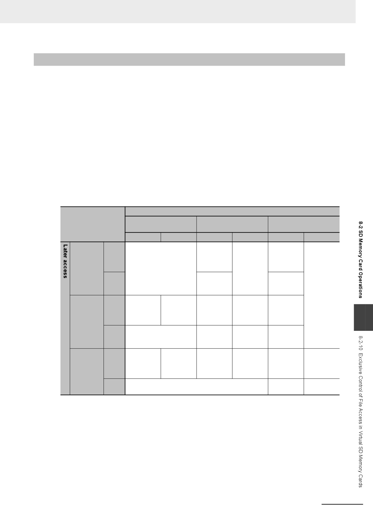
The following table shows the combinations of operations that require exclusive controls.
When you use a combination of operations that requires exclusive controls, execute the later process-
ing only after checking that the first processing is finished.
First access
File Operations from the
Instructions*1
FTP server
Sysmac Studio
Reading
Writing
Reading
Writing
Reading
Writing
Exclusive control is per-
Exclusive
Perform
Exclusive
Perform
Read-
formed automatically, and
control is
exclusive
control is
exclusive
ing
an error occurs for the
not
control.
not
control.
Instruc-
instruction that is executed
required.
required.
tions
later.
Perform
Perform
Writ-
exclusive
exclusive
ing
control.
control.
Exclusive
Perform
---
---
Exclusive
File
Read-
control is
exclusive
control is
operations
ing
not
control.
not
8
from the
required.
required.
Sysmac
Perform exclusive control.
---
---
Perform
Writ-
Studio
exclusive
ing
control.
Exclusive
Perform
Exclusive
Perform
---
---
Read-
control is
exclusive
control is
exclusive
ing
not
control.
not
control.
FTP server
required.
required.
Writ-
Perform exclusive control.
---
---
ing
*1
The instructions include the SD Memory Card instructions and the FTP client communications instructions.
For an NY-series Controller, you can access files in the shared folder from Windows.
In such case, perform exclusive controls according to the specifications for sharing files of Windows.
8-15
8 Controller Functions
8-3
Security
This section describes the security functions that are supported by the NY-series Controller.
To protect your assets, you can use security functions to protect the user program and data in the Con-
troller. To prevent incorrect operation, you can use security functions to restrict operations on the Sys-
mac Studio.
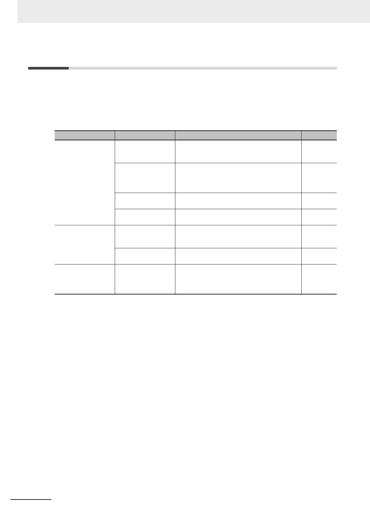
The NY-series Controller supports the following security functions.
Application
Security function
Outline of function
Reference
Prevention of the theft
Authentication of user
This ensures that a user program cannot be
8-17
of assets
program execution
operated on another Controller even if the user
IDs
program is copied.
User program trans-
You can transfer the user program to the Control-
8-20
fer with no restoration
ler without the source code. This prevents any-
information
one from displaying the user program on another
computer even if they upload it.
Overall project file
You can place a password on a project file to pro-
8-21
protection
tect your assets.
Data protection
You can place protection on part of the data in a
8-22
project file to protect your assets.
Prevention of incor-
Operation authority
You can set operation authorities to restrict the
8-24
rect operation
verification
operations that can be performed on the Control-
ler from the Sysmac Studio.
CPU Unit write protec-
You can prevent rewriting data in the Controller
8-26
tion
from the Sysmac Studio.
Prevention of incor-
CPU Unit names
You can check to see if the Controller name and
8-27
rect connections
serial ID on the computer and in the Controller
are the same to prevent going online with the
wrong Controller.
8-16
8 Controller Functions
8-3-1
Authentication of User Program Execution IDs
Introduction
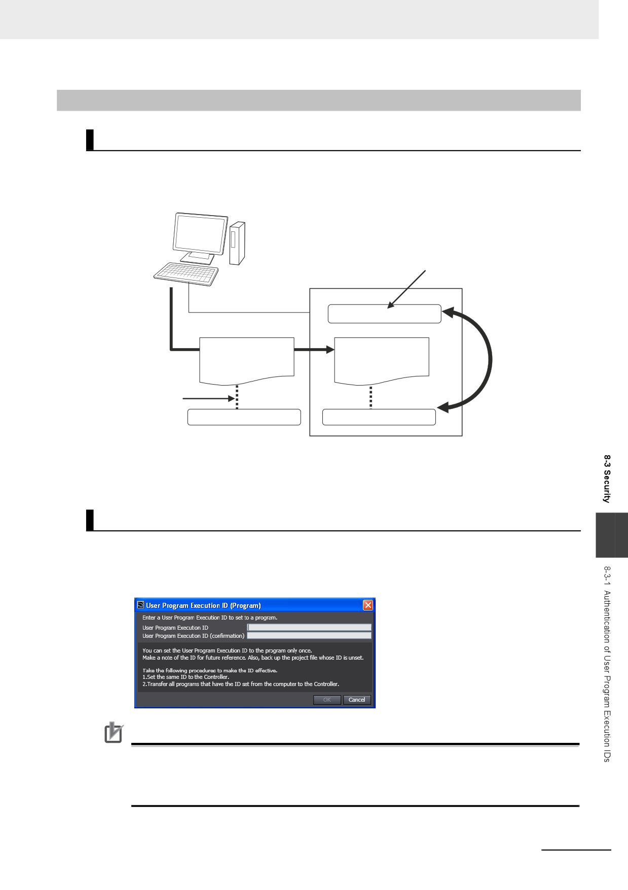
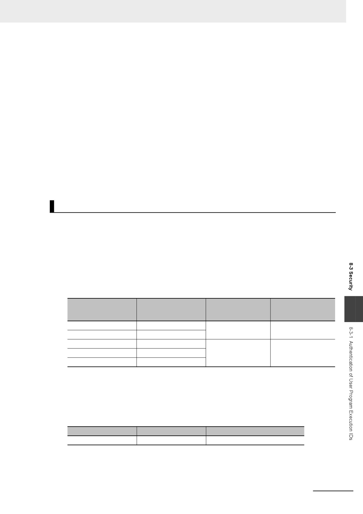
You can set a specific ID (called a user program execution ID) in the Controller in advance. If you do,
you can execute only a user program with the same ID.
Sysmac Studio
A user program execution ID
is registered in the Controller.
Controller
User program execution ID
Download
The Controller can
User program
User program
execute the user
program only when
these two match.
User program
execution ID assigned
to user program.
User program execution ID
User program execution ID
You can prevent a user program from use on a different Controller (hardware).
In contrast to the protection function, you can still display and edit the user program even if a user pro-
gram execution ID is set.
Operating Procedure
8
1 Always backup the project files before you assign a user program execution ID.
2 Assign the user program execution ID to the user program offline from the Sysmac Studio.
Precautions for Correct Use
After you assign a user program execution ID to a user program, you cannot change or delete
the ID. To use a different ID, read the project file without an ID that was backed up in step 1,
above, and assign another user program execution ID. To delete the ID, use the project file with-
out an ID that was backed up in step 1, above.
8-17
8 Controller Functions
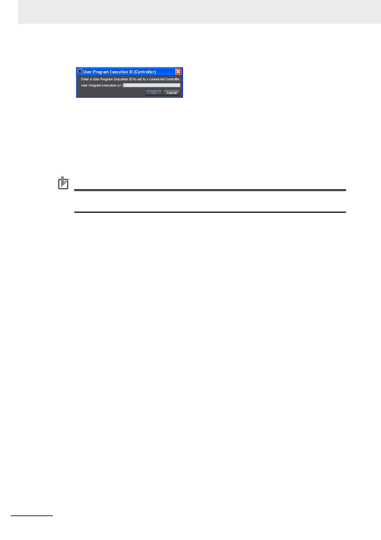
3 Connect the Sysmac Studio online and register the user program execution ID that was set in
step 2 in the Controller.
The registration of the user program execution ID in the Controller is recorded in the event log.
At this time, the user program execution ID in the Controller is overwritten even if it is already
registered.
4 Transfer the user program with the same user program execution ID to the Controller.
If the user program execution ID in the user program does not match the user program execu-
tion ID in the Controller or if one of them does not have an ID, an ID Verification Error (major
fault level Controller error) occurs when you attempt to change to RUN mode and the Controller
will not operate.
Precautions for Correct Use
After you assign a user program execution ID to the Controller, you cannot read or delete the ID.
To delete the ID from the Controller, perform the Clear All Memory operation on the Controller.
z Operation When an ID Verification Error Occurs
When the User Program Execution ID in the Controller Is Incorrect or Not
Registered:
Connect online to the Controller from the Sysmac Studio and perform the following steps.
1 Overwrite or register the correct user program execution ID in the Controller.
2 Cycle the power supply to the Controller, or reset the Controller from the Sysmac Studio.
When the User Program Execution ID Is Not Assigned to the User Program or
Is Incorrect
1 Read the backed up project file from the Sysmac Studio, and assign the correct user program
execution ID.
2 Connect the Sysmac Studio to the Controller online and transfer the user program.
3 Cycle the power supply to the Controller, or reset the Controller from the Sysmac Studio.
8-18
8 Controller Functions
z Other Situations
To Delete the User Program Execution ID Assigned to the User Program:
Read the backed up project file in the Sysmac Studio.
To Delete the User Program Execution ID from the Controller:
Connect the Sysmac Studio to the Controller online and perform the Clear All Memory operation.
To Check the User Program Execution ID Assigned to the User Program:
For security, the user program execution ID that is assigned to the user program cannot be checked
from the Sysmac Studio. Read the backed up project file in the Sysmac Studio and set the user pro-
gram execution ID again.
To Check the User Program Execution ID in the Controller:
For security, the user program execution ID that is set in the Controller cannot be checked from the
Sysmac Studio. Perform the Clear All Memory operation and register the correct user program exe-
cution ID.
Specifications
z
User Program Execution ID Verification Specifications
Timing of Verification
At startup, the Controller compares the user program execution ID that is registered in the Controller
with the user program execution ID that is assigned to the user program.
Verification Conditions
The conditions for verifications are given in the following table.
“A” and “B” indicate the IDs.
User program execution
User program execution
ID that is registered in
ID that is assigned to the
Error
Operation
8
the Controller
user program
A
A
None
Possible
None
None
None
A
ID Verification Error
Not possible.
A
None
A
B
Operation When the IDs Do Not Match
When the IDs do not match, an ID Verification Error (major fault level Controller error) occurs, and
the Controller does not operate. However, to reset the error you must cycle the power supply to the
Controller or reset the Controller from the Sysmac Studio.
z
User Program Execution ID Character Specifications
Usable characters
Case sensitivity
Maximum size (without NULL)
0 to 9, A to Z, and a to z
Case sensitive
8 to 32 characters
8-19
8 Controller Functions
8-3-2
User Program Transfer with No Restoration Information
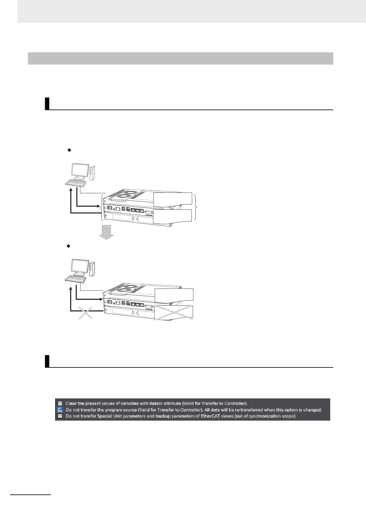
You can transfer the user program to the Controller without the source code. This prevents anyone from
displaying the user program on another computer even if they upload it.
Introduction
Normally, when you transfer the user program from the Sysmac Studio to the Controller, information is
transferred to restore it.
This function does not transfer information for restoration. That makes it impossible to read the user
program.
Normal Transfer
Sysmac Studio
Controller
User program
(for execution)
Normally, both
User program
Readable
(restoration
are transferred.
information)
User Program Transfer with No Restoration Information
Sysmac Studio
Controller
User program
(for execution)
User program
Restoration information
(restoration
information)
is not transferred.
Not readable
This function is used to prevent theft of user program data when on-site maintenance of the user pro-
gram is not required.
Operating Procedure
When you transfer the user program to the Controller, select the Do not transfer program source
Check Box in the Synchronization Window of the Sysmac Studio and then click the Transfer to Con-
troller Button.
8-20
8 Controller Functions
8-3-3
Overall Project File Protection
You can place a password on a project file to protect your assets.
Operating Procedure
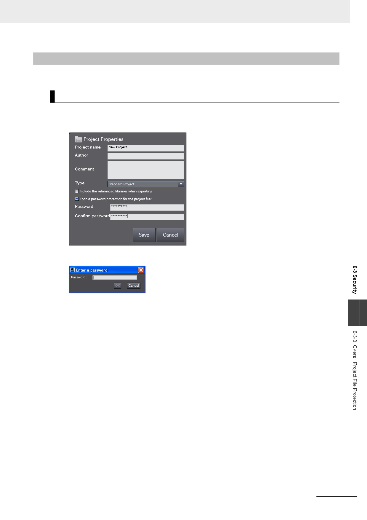
This section describes how to set a password for a project. When you use Save As to save the proj-
ect file, select the Enable password protection for the project file Check Box to enable setting a
password.
Use the following procedure to open a project for which a password is set. If you try to open or
import a project file for which a password is set, the Enter a Password Dialog Box is displayed.
Refer to the Sysmac Studio Version 1 Operation Manual (Cat. No. W504) for specific procedures.
8
8-21
8 Controller Functions
8-3-4
Data Protection
You can place protection on part of the data in a project file to protect your assets.
Introduction
You can place protection on part of the data in a project file to restrict access to that data. You can
select any of three levels of access restrictions when you set protection. Protection must be temporarily
cleared to access the restricted data. The length of time for which protection is cleared depends on the
operation that you use.
Protected Data
Protection can be set for the following data. Only change protection can be set for cam profiles.
• Ladder diagrams (applies to programs, functions, and function blocks)
• ST (applies to programs, functions, and function blocks)
• Cam profiles
Levels of Access Restrictions
You can select one of the following levels of access restrictions.
• Prohibiting copying, displaying, and changing the data
• Prohibiting displaying and changing the data
• Prohibiting changing the data
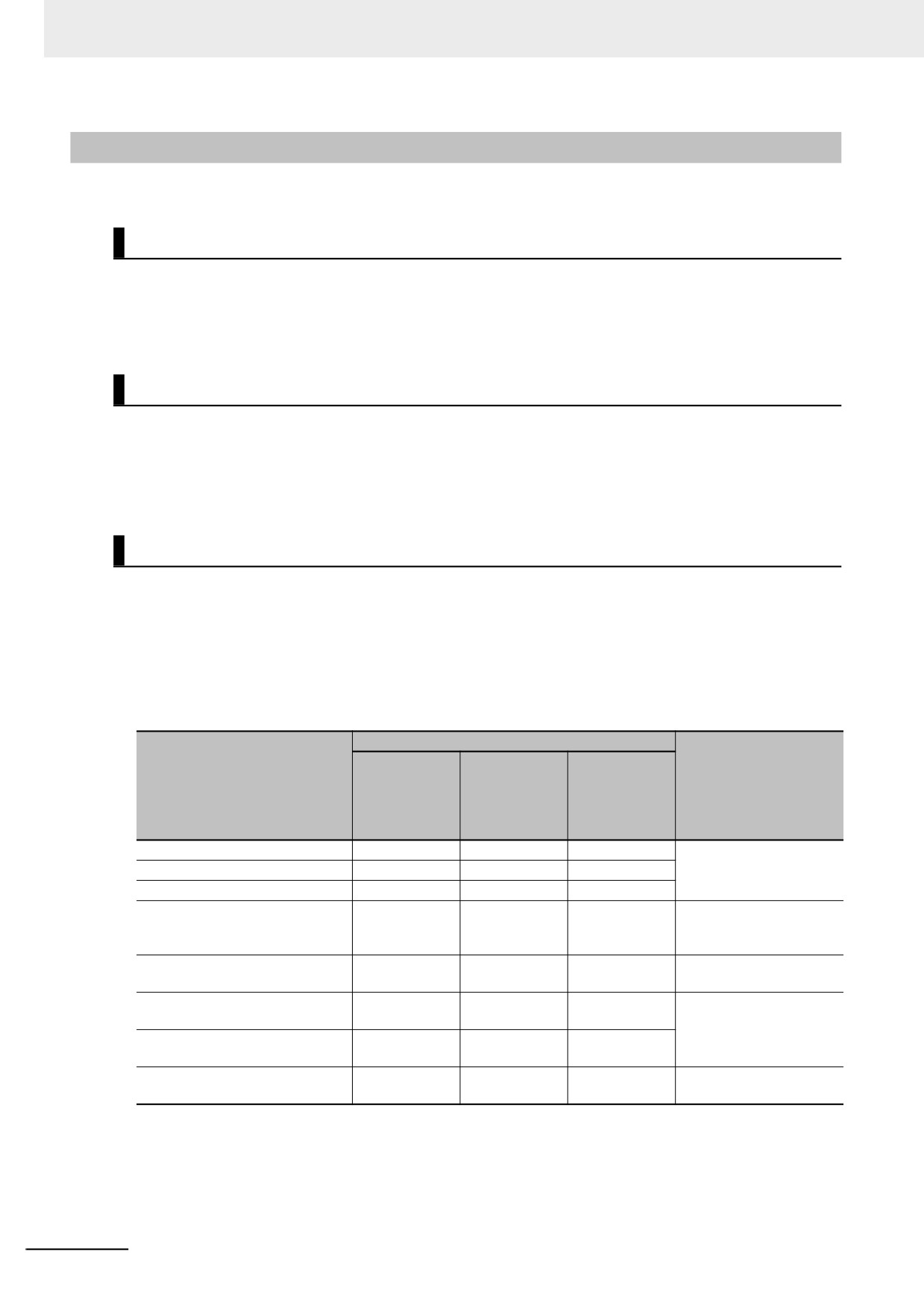
The following table shows the data access methods, restrictions for each restriction level, and the
length of time that protection is cleared.
Levels of access restrictions
Prohibiting
Prohibiting
copying, dis-
Prohibiting
Length of time that pro-
Data access operation
displaying
playing and
changing the
tection is cleared
and changing
changing the
data
the data
data
Displaying the data
Restricted.
Restricted.
Not restricted.
While the project is open
Printing the data
Restricted.
Restricted.
Not restricted.
Changing the data
Restricted.
Restricted.
Restricted.
Copying the data
Restricted.
Not restricted.
Not restricted.
Protection must be tem-
porarily cleared for each
operation
Displaying basic comparison
Not restricted.
Not restricted.
Not restricted.
This operation is not
results
restricted.
Displaying detailed comparison
Restricted.
Restricted.
Not restricted.
While the project is open
results
Jumping from an event log or
Restricted.
Restricted.
Not restricted.
cross-reference to the data
Registering objects in a library
Restricted.
Not restricted.
Not restricted.
Not possible to clear pro-
tection temporarily.
8-22