Omron IPC Machine Controller Industrial Panel PC / Industrial Box PC. Software User’s Manual (Industrial PC Platform NY-series) - page 11
6 Programming
•
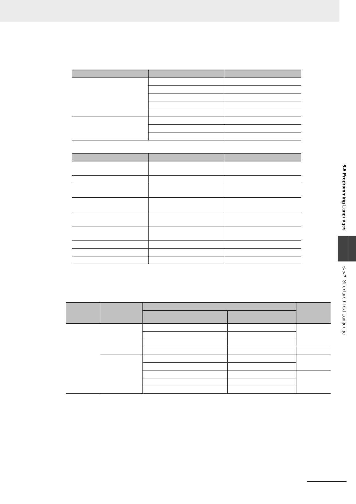
Function Block Definition
Function block name: ConvData32ToDouble
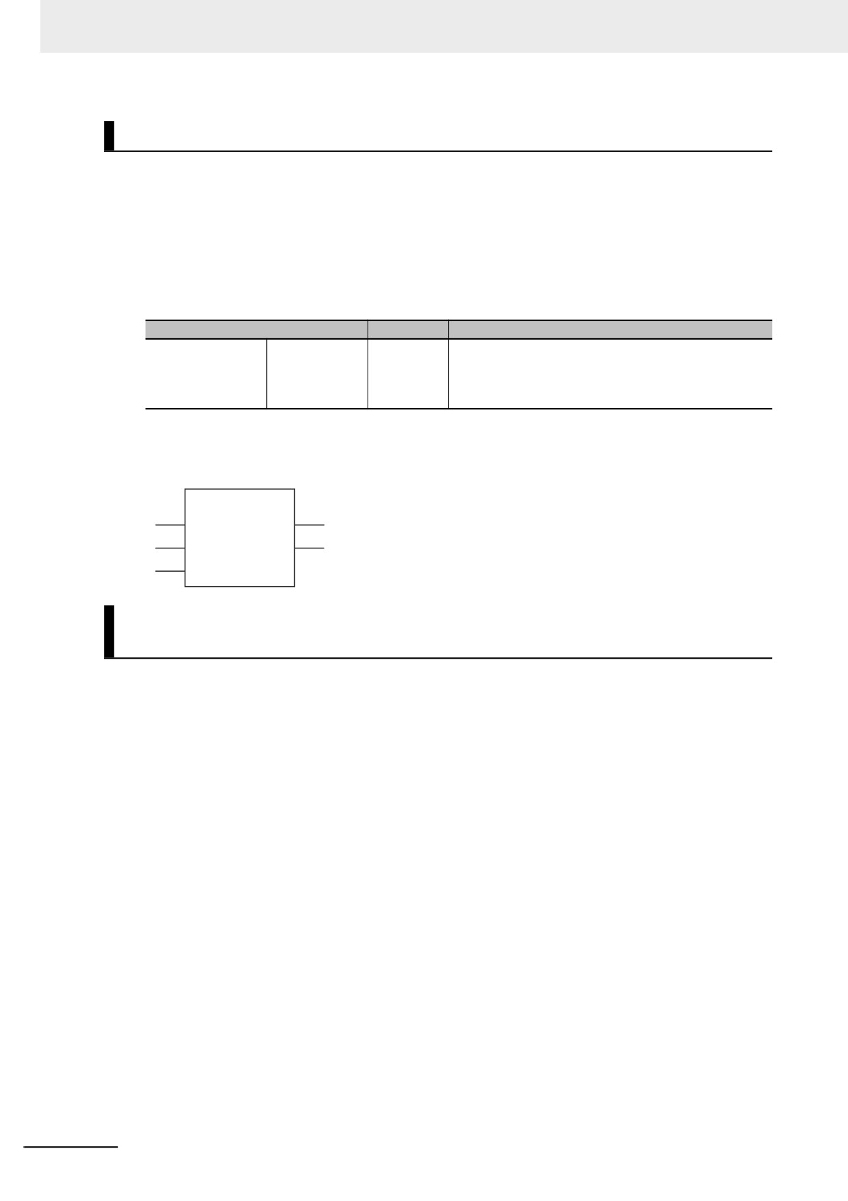
Function Block Variables
I/O
Variable name
Data type
Input variables
Execute
BOOL
Data32_1
DINT
Data32_2
DINT
NoOfDigit_1
INT
NoOfDigit_2
INT
Output variables
OK
BOOL
Double_1
LREAL
Double_2
LREAL
•
Program Variables
Variable name
Data type
Comments
ChangeFixToFloat
ConvData32ToDouble
Convert from fixed-point to
floating-point.
Exe
BOOL
Execution trigger
FixPointData1
DINT
Decimal point position specifi-
cation data 1
FixPointPos1
INT
Number of digits below deci-
mal point 1
FixPointData2
DINT
Decimal point position specifi-
cation data 2
FixPointPos2
INT
Number of digits below deci-
mal point 2
Done
BOOL
Normal end
6
RealData1
LREAL
Floating-point data 1
RealData2
LREAL
Floating-point data 2
Omitting Parameters
When you call a function block, you can omit parameters that are not required. The following table
shows when you can omit parameters.
Variables for
Notation pattern
POU type
the called
Omission
Parameters included
Examples
POU
FB
Given (notation
All parameters given
instance(x:=a,y:=b,z:=c);
OK
method 1)
More than one parameter given
instance(x:=a,y:=b);
One parameter given
instance(y:=b);
No parameters given
instance(x:=);
---
Given (notation
All parameters given
instance(a,b,c);
OK
method 2)
All parameters not given
instance();
Only the first parameter given
instance(a);
---
One parameter given
instance(a, , );
More than one parameter given
instance(a,b);
OK: Possible (initial used), ---: A building error will occur.
6-123
6 Programming
z
Function Calls
Overview:
This statement calls a function.
Reserved Words: None
Statement Structure:
Give the output parameter to which the return value is assigned on the left side of the assignment
keyword (:=). On the right side, give the argument specifications (to pass the values of the specified
variables to the input variables of the called function) inside the parenthesis after the function name.
There are two methods of writing this statement, as shown in (1) and (2) below.
We recommend method (1) for program readability.
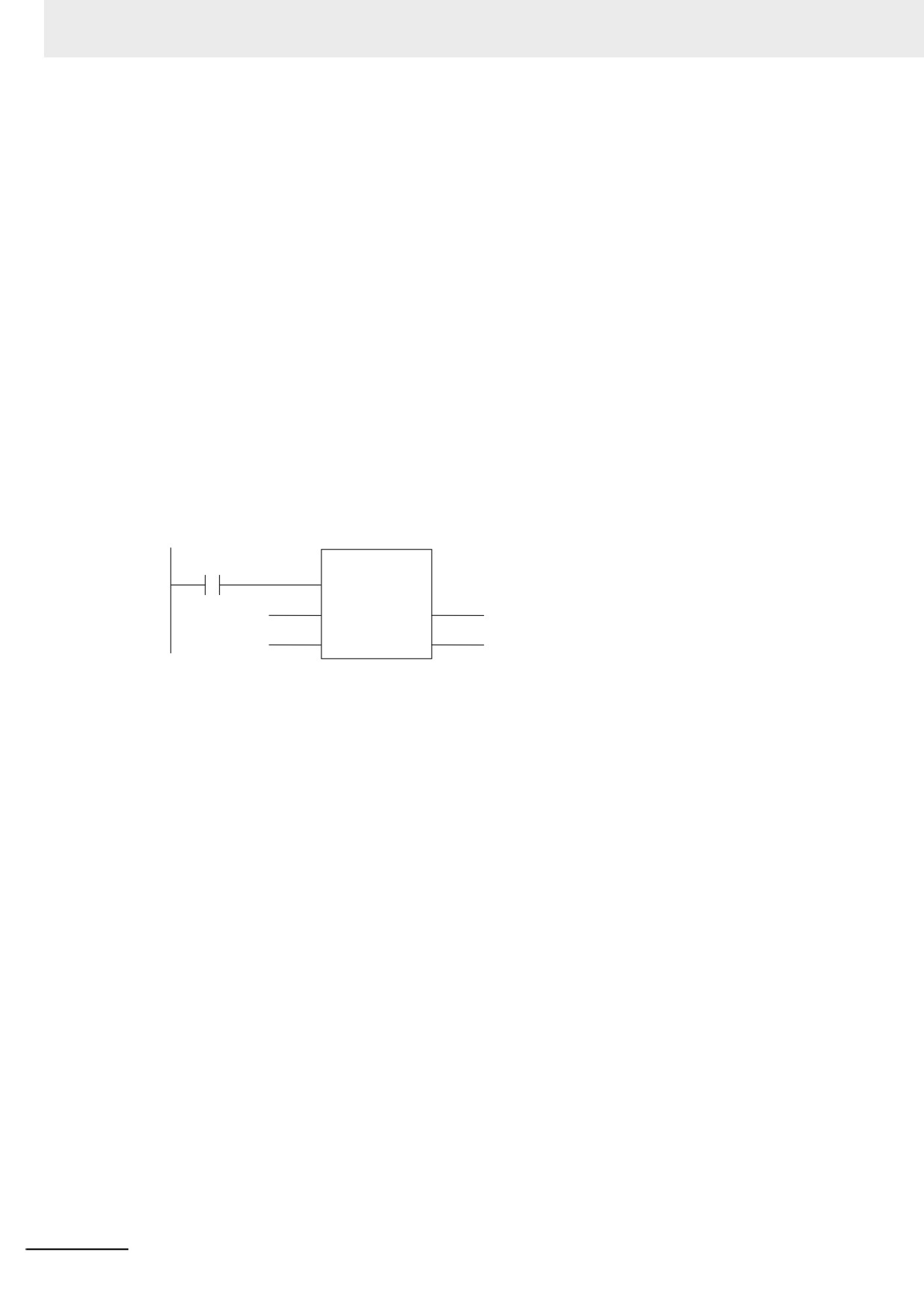
Notation Method 1:
IF (x0=TRUE) THEN
y1 := MyFUN(A:=x1, B:=x2, C=>y2);
END_IF;
•
Ladder Diagram Expression
MyFUN
x0
EN
ENO
x1
y1
A
x2
y2
B
C
MyFUN: Function name
x0: Specifies whether to call the function.
A and B: Input variable names of the called function
x1 and x2: Input parameters of the called function
C: Output variable name of the called function
y1: Storage location for the return value from the called function
y2: Output parameters of the called function
•
You can give the arguments in any order.
•
You can omit the input variable names and input parameter names. If they are omitted, the input
variables are assigned their initial values.
•
You can omit EN as well. If it is omitted, EN is assigned a value of TRUE.
6-124
6 Programming
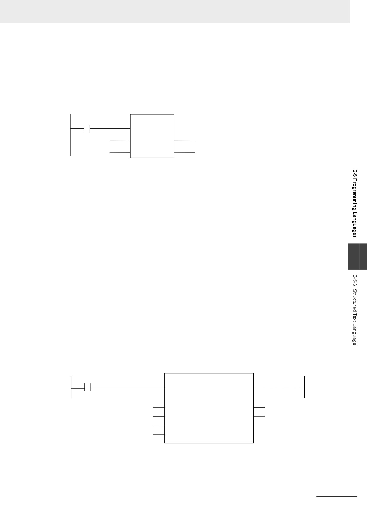
Notation Method 2:
Omit the variable names of the called function and give the parameter names of the calling POU.
IF (x0=TRUE) THEN
y1 := MyFUN(x1, x2, y2);
END_IF;
• Ladder Diagram Expression
MyFUN
x0
EN
ENO
x1
y1
A
x2
y2
B
C
MyFUN: Function name
x0: Specifies whether to call the function.
A and B: Input variable names of the called function
x1 and x2: Input parameters of the called function
C: Output variable name of the called function
y1: Storage location for the return value from the called function
y2: Output parameters of the called function
• The order of parameters is based on the function definition. The order is the same as the local
variable definition for the function, from top to bottom.
6
Example:
• Programming
• Notation 1
ConvData32ToDouble(Data32_1:=FixPointData1,Data32_2:=FixPointData2,
NoOfDigit_1:=FixPointPos1, NoOfDigit_2:=FixPointPos2,
Double_1=>RealData1, Double_2=>RealData2);
• Notation 2
ConvData32ToDouble(FixPointData1, FixPointData2, FixPointPos1, FixPointPos2,
RealData1, RealData2);
• Ladder Diagram Expression
P_On
ConvData32ToDouble
EN
FixPointData1
Data32_1
Double_1
RealData1
FixPointData2
Data32_2
Double_2
RealData2
FixPointPos1
NoOfDigit_1
FixPointPos2
NoOfDigit_2
6-125
6 Programming
•
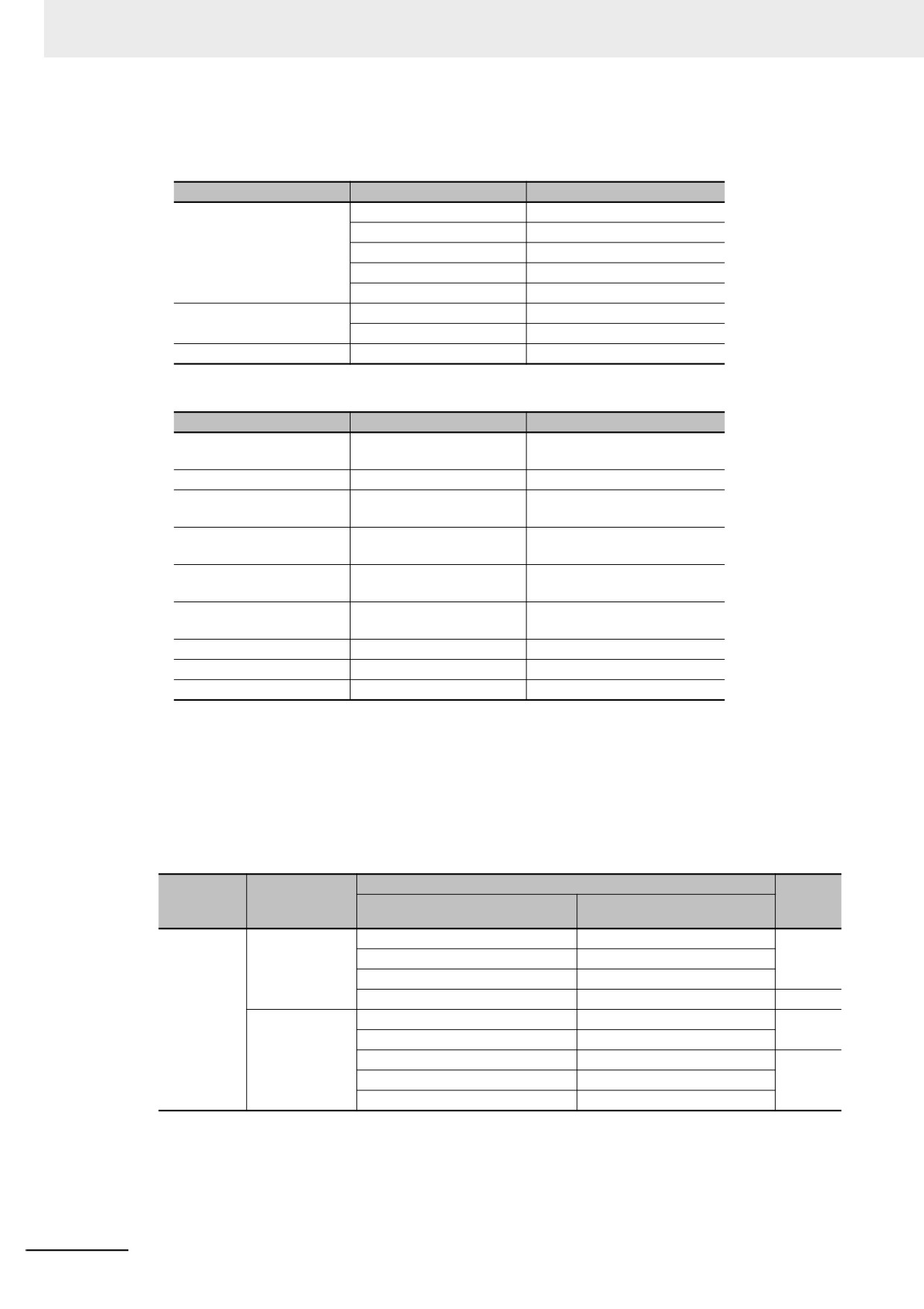
Function Definition
Function name: ConvData32ToDouble
Function Variables
I/O
Variable name
Data type
Input variables
Execute
BOOL
Data32_1
DINT
Data32_2
DINT
NoOfDigit_1
INT
NoOfDigit_2
INT
Output variables
Double_1
LREAL
Double_2
LREAL
Return value
---
BOOL
•
Program Variables
Variable name
Data type
Comment
ChangeFixToFloat
ConvData32ToDouble
Convert from fixed-point to
floating-point.
Exe
BOOL
Execution trigger
FixPointData1
DINT
Decimal point position specifi-
cation data 1
FixPointPos1
INT
Number of digits below deci-
mal point 1
FixPointData2
DINT
Decimal point position specifi-
cation data 2
FixPointPos2
INT
Number of digits below deci-
mal point 2
Done
BOOL
Normal end
RealData
LREAL
Floating-point data 1
RealData
LREAL
Floating-point data 2
Application:
This statement calls a function.
Omitting Parameters
When you call a function, you can omit parameters that are not required. The following table shows
when you can omit parameters.
Variables for
Notation pattern
Omis-
POU type
the called
Parameters included
Example
sion
POU
FUN
Given (notation
All parameters given
FUN(x:=a,y:=b,z:=c);
OK
method 1)
More than one parameter given
FUN(x:=a,y:=b);
One parameter given
FUN(y:=b);
No parameters given
FUN(x:=);
---
Given (notation
All parameters given
FUN(a,b,c)
OK
method 2)
No parameters given
FUN();
Only the first parameter given
FUN(a);
---
One parameter given
FUN(a, , );
More than one parameter given
FUN(a,b);
OK: Possible (initial used), ---: A building error will occur.
6-126
6 Programming
Precautions for the ST Language
Observe the following precautions when you use the ST language in the user program.
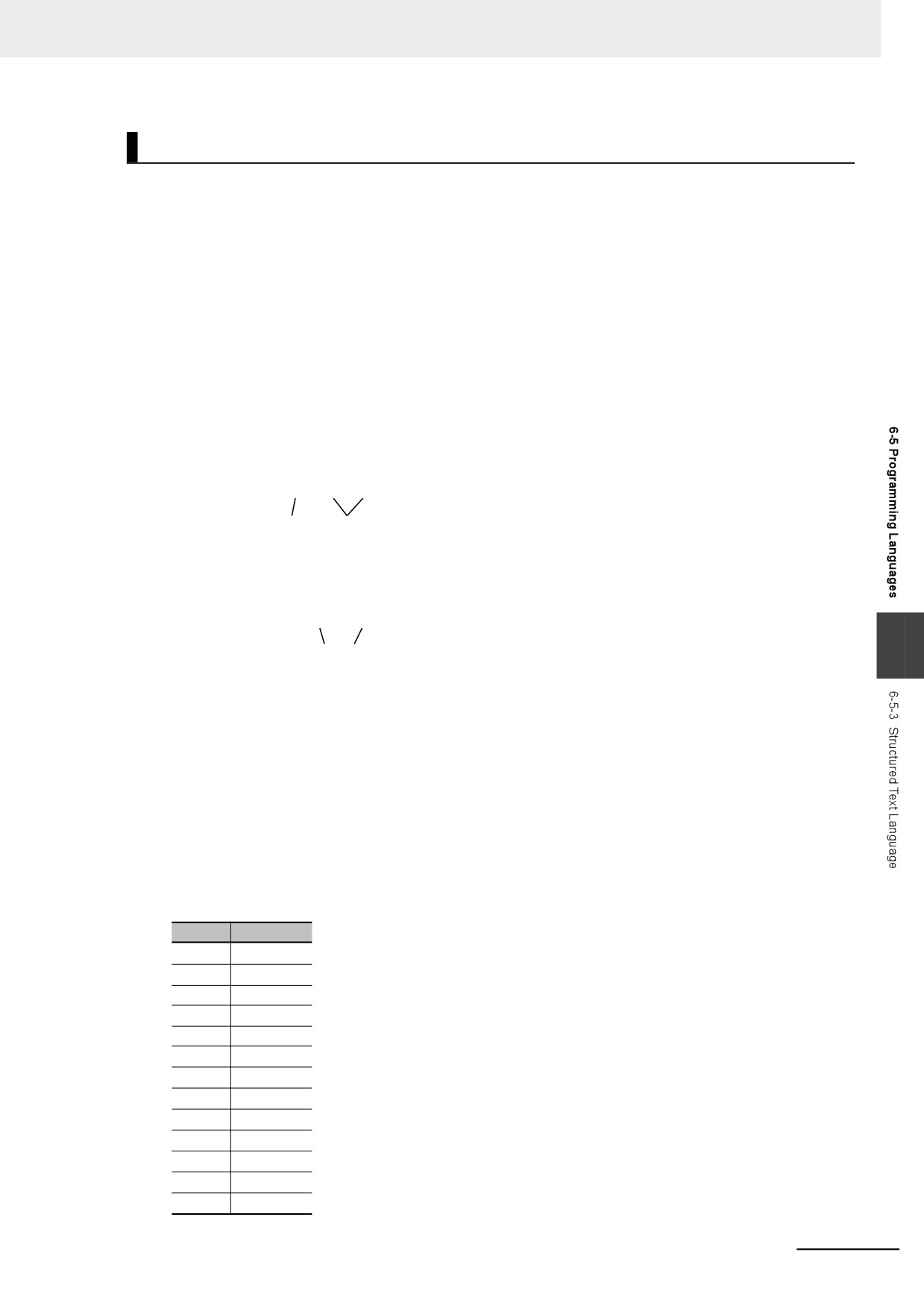
z
Implicit Casts
If the data types of the operands do not match, as shown below, the data types are converted auto-
matically according to the implicit cast rules. If the implicit cast rules are not satisfied, a building error
occurs.
(1) When the data types of the operands in the expression on the right side of the
assignment statement are not the same
Example:
A: = INT#10 + SINT#2;
(2) When the data types of the operands on the right and left sides of the assignment
statement are not the same
Example:
A: = B + C;
REAL INT
(3) When the data types of the operands in statement are not the same
Example:
INT LINT
6
CASE A+B OF
INT#1:
def:=INT#10;
The casting rules are described for the following three cases.
Casting Rules When the Right-hand Side of an Assignment Statement Is an
Arithmetic Expression
• For the right-hand operand, you can use any combination of the data types that are supported for
the operator operand.
• Of the operands on the right side, the operand with the highest rank is considered the data type of
the entire side. (Refer to the Data Type Ranking Table given below for the data type ranks.)
Data Type Ranking Table:
The higher the rank, the larger the range of numerical values that the data type can express.
Rank
Data type
1
SINT
2
USINT
3
INT
4
UINT
5
DINT
6
UDINT
7
LINT
8
ULINT
9
REAL
10
LREAL
11
BYTE
12
WORD
13
DWORD
6-127
6 Programming
Rank
Data type
14
LWORD
Casting Rules When You Assign the Right-hand Value to the Left-hand Side
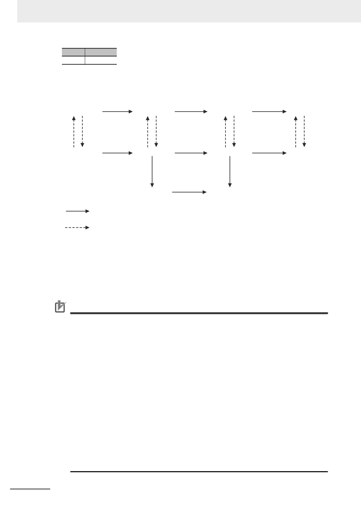
In the following chart, a cast is performed if an arrow connects the data type of the source to the
data type of the assignment destination. Any combination that is not connected will cause a building
error.
USINT
UINT
UDINT
ULINT
SINT
INT
DINT
LINT
REAL
LREAL
When you assign the value, the sign and absolute value of the number do not change.
When you assign the value, the sign and absolute value of the number may change.
Example: intVar := -1; (* intVar := 16#FFFF *)
uintVar := 1;
uintVar := intVar;
(* uintVar:= 16#FFFF, or −1 was
assigned but the result is 65535 *)
Even if the arrow does not connect directly to a data type, you can still perform assignments for the
data types. For example, SINT->USINT->UINT->UDINT->ULINT are all connected, so you can write
an assignment such as ULINT:=SINT.
Precautions for Correct Use
Observe the following precautions when casting UDINT to ULINT data, DINT to LINT data, or
DINT to LREAL data.
All of these are casts from 32-bit data to 64-bit data. If the result of the calculation of the right
side of the assignment statement exceeds the range of 32-bit data, the correct value may not be
assigned.
Example: For the following assignment statements, the result of the addition in the third state-
ment exceeds the range of 32-bit data. An overflow will result and 0 will be assigned
to LintVar.
UdintVar := UDINT#16#FFFF_FFFF;
// Upper limit of 32-bit data
DintVar
:= DINT#1;
// 1
LintVar := (UdintVar + DintVar)/DINT#2;
// (Upper limit of 32-bit data + 1)/2
In a case like this one, convert the data to 64-bit data before you perform the calculation. To do
this for the above example, change the assignment status as shown below.
LintTmp1 := UDINT_TO_LINT(UDINT#16#FFFF_FFFF); //Convert UDINT to LINT data.
LintTmp2 := DINT_TO_LINT(DINT#1);
// Convert DINT to LINT data.
LintVar
:= (LintTmp1 + LintTmp2) / DINT#2;
6-128
6 Programming
Casting Rules in Expressions in Statements
The implicit cast rules for right-hand arithmetic expressions in assignment statements and for
assigning the value of the right-hand side to the left-hand side also apply to expressions in state-
ments.
Example:
CASE (A+B+C) OF
Result1:
to
ResultN:
to
END_CASE;
z
Order of Execution of Functions
The order of execution of functions is not defined for functions in expressions. The order of execu-
tion of functions depends on the unit version of the NY-series Controller, the version of the Sysmac
Studio, and the notation. Precaution is required in cases where the results of an expression may
depend on the order of execution of the functions, such as in the following cases.
• Expressions that contain more than one function that access the same global variable
• Expressions that contain a function and a variable whose value is changed by that function
Expressions That Contain More Than One Function That Access the Same
Global Variable
In the following example, the order of execution of the three functions is not necessarily the same as
the order of execution of the calculations, which is determined by the priority of the operators.
Therefore, it is possible that the functions are executed in the following order: FUN2, FUN3, and
6
then FUN1.
result := FUN1() + FUN2() * FUN3();
If all three of the functions in the above expression access and write the same global variable, the
value of the result variable may change depending on the order of execution of the functions.
To ensure that the three functions are always executed in the same order, the expression is broken
up. The following notation is used to execute the functions in the following order: FUN2, FUN3, and
then FUN1.
tmp2 := FUN2();
tmp3 := FUN3();
result := FUN1() + tmp2 * tmp3;
Expressions That Contain a Function and a Variable Whose Value Is Changed
by That Function
The following expression contains a function and a variable whose value is changed by that func-
tion.
result := varA + FUN4(out => varA);
In the above expression, the first element on the right side, variable varA, is not necessarily evalu-
ated before FUN4 is executed. Therefore, the value of the result variable may change depending on
the order of varA evaluation and FUN4 execution.
To ensure that varA evaluation and FUN4 execution always occur in the same order, the expression
is broken up. The following notation is used to evaluate varA first and then execute FUN4.
tmp
:= varA;
result := tmp + FUN4(out => varA);
The following notation is used to execute FUN4 first and then evaluate varA.
tmp
:= FUN4(out => varA);
result := varA + tmp;
6-129
6 Programming
z Calculation Precision of Expressions with Constants without Data Type
Specifications
The calculation precision of an expression that contains a constant without a data type specification
is automatically determined by the data types of the variables and constants that are given in the
expression and destination.
Notation of Constants
If a constant is given without a decimal point, such as 100, it is processed as an integer. If a constant
is given with a decimal point, such as 100.0, it is processed as a real number.
Expression Calculation Precision
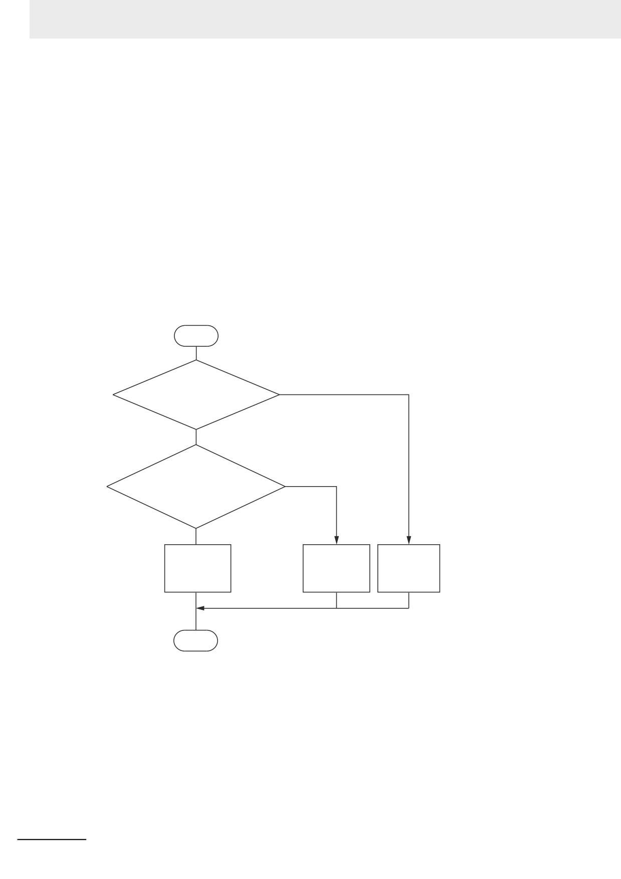
The calculation precision of an expression is either 32-bit integer, 64-bit integer, or long real preci-
sion depending of the data types of the variables and constants given in the expression and destina-
tion. The following rules apply to the calculation precision of an expression.
START
Yes
Real number constant or
variable in expression or
destination?
No
Constant or variable greater
Yes
than 32 bits in expression or
destination?
No
Calculation
Calculation
Calculation
performed with
performed with
performed
32-bit integer
64-bit integer
with long real
precision.
precision.
precision.
END
6-130
6 Programming
Example: realv := 2 + 3 * 4; // The data type of the realv variable is REAL.
The realv variable is a real number, so the calculation is performed with long real precision. The
calculation result is 14.0.
realv := 2 + 3.0 * 4; // The data type of the realv variable is REAL.
The 3.0 constant and the realv variable are real numbers, so the calculation is performed with
long real precision. The calculation result is 14.0.
lintv := 2 + 3 * 4; // The data type of the lintv variable is LINT.
There is no constant or variable that is a real number, but the lintv variable exceeds 32 bits, so
the calculation is performed with 64-bit integer precision. The calculation result is 14.
intv := 2 + 3 * 4; // The data type of the intv variable is INT.
There is no constant or variable that is a real number and there is no constant that exceeds 32
bits, so the calculation is performed with 32-bit integer precision. The calculation result is 14.
However, the calculation precision of division is determined only by the divisor and dividend. The
rules for determining the calculation precision are the same as those in the previous flowchart.
Example: realv := 2 / 3 * 4; // The data type of the realv variable is REAL.
Dividing 2 by 3 does not include an integer that exceeds 32 bits for the divisor or dividend, so the
calculation is performed with 32-bit integer precision. The calculation result is 0.
In the next step, the realv variable is a real number, so the calculation of 0 * 4 is performed with
long real precision. The calculation result is 0.0.
Precautions for Correct Use
6
The calculation precision of an expression that contains a constant without a data type specifica-
tion is automatically determined by the notation of the constant and the data types of the vari-
ables that are given in the expression. Therefore, calculations may be performed with
unintended precision. We recommend that you specify the data type for real numbers, such as
REAL#1.0.
6-131
6 Programming
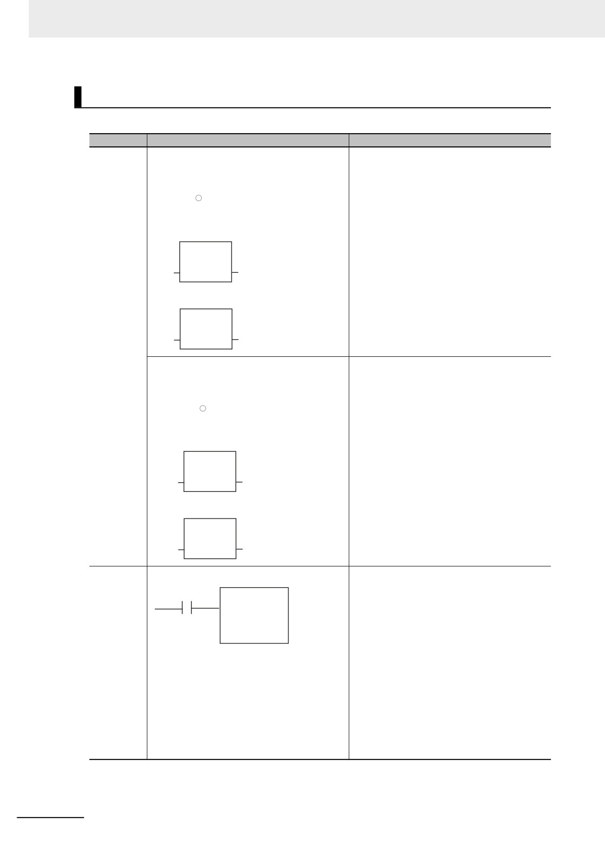
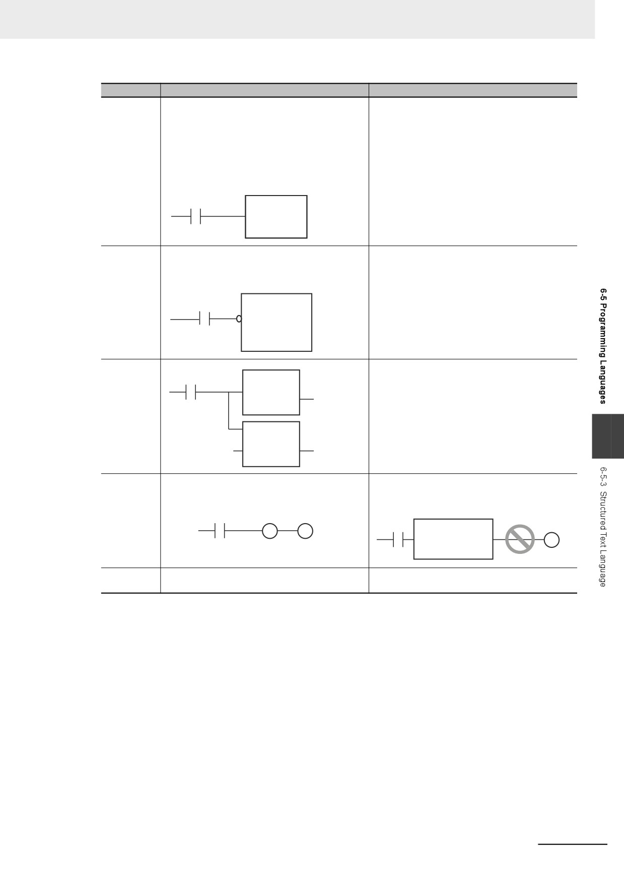
Differences between ST and Ladder Diagrams
The differences between ST and ladder diagrams are described below.
Item
Ladder diagram
ST (including inline ST)
Input differ-
z Change to TRUE
z Change to TRUE
entiation
•
Method 1
• Method 1
R_TRIG_instance (Clk:=start, Q=>do);
start
do
----|↑|-----------
R_TRIG_instance is an instance of
the
R_TRIG instruction.
• Method 2
R_TRIG_instance
R_TRIG
start
Clk
Q
do
• Method 3
Up
start
In
do
z Change to FALSE
z Change to FALSE
•
Method 1
• Method 1
F_TRIG_instance (Clk:=start, Q=>do);
start
do
----|↓|-----------
F_TRIG_instance is an instance of
the
F_TRIG instruction.
• Method 2
F_TRIG_instance
F_TRIG
start
Clk
Q
do
• Method 3
Down
start
In
do
Instruction
z Upward Differentiation
z Upward Differentiation
differentia-
There is no equivalent in ST. You must create it
tion
start
@Inst
in logic.
Example:
• Method 1
R_TRIG_instance (Clk:=start, Q=>do);
IF (do = TRUE) THEN Inst();
END_IF;
• Method 2
IF (start = TRUE) THEN
IF (pre_start = FALSE) THEN Inst();
END_IF;
END_IF;
pre_start:=start;// Update previous value.
6-132
6 Programming
Item
Ladder diagram
ST (including inline ST)
Instructions
With the TON instruction, multiple cycles are
You must declare two instances, one for
that last
required from the start of instruction execution
execution and one to reset, as shown below.
multiple
to the end and the instruction is reset when the
IF (start = TRUE) THEN
task periods
power flow is FALSE. Therefore, you need to
TON_instance(In:=TRUE, omitted);
declare only one instance to both execute the
// Start timer.
instruction and reset it.
ELSE
TON_instance(In:=FALSE, omitted);
TON_instance
// Reset timer.
start
TON
END_IF;
In
Q
PT
ET
Func-
Add a circle to indicate reversal at the intersec-
Add a NOT operator to the argument.
tion/function
tion of the BOOL argument and the func-
* You can add NOT operators to any BOOL
block argu-
tion/function block.
variable, not just arguments.
ment rever-
sal
emergency
Func
specifica-
IF (NOT emergency) THEN
EN
ENO
tions
Func();
END_IF;
Multi-stage
IF(start=TRUE) THEN
connections
start
Func1
Func2( in := Func1());
EN ENO
END_IF;
tmp
Func2
6
EN ENO
tmp
in
Post-con-
You can connect only other Out instructions
You cannot continue the ladder diagram after
necting lad-
after an Out instruction.
inline ST.
der
instructions
NG
// Inline ST
str :=‘ABC’;
Program
You can create sections.
You cannot create sections.
divisions
6-133
6 Programming
6-6
Instructions
This section describes the instructions that are pre-defined by the NY-series Controller.
For details on these instructions, refer to the NY-series Instructions Reference Manual (Cat. No. W560)
and NY-series Motion Control Instructions Reference Manual (Cat. No. W561).
6-6-1
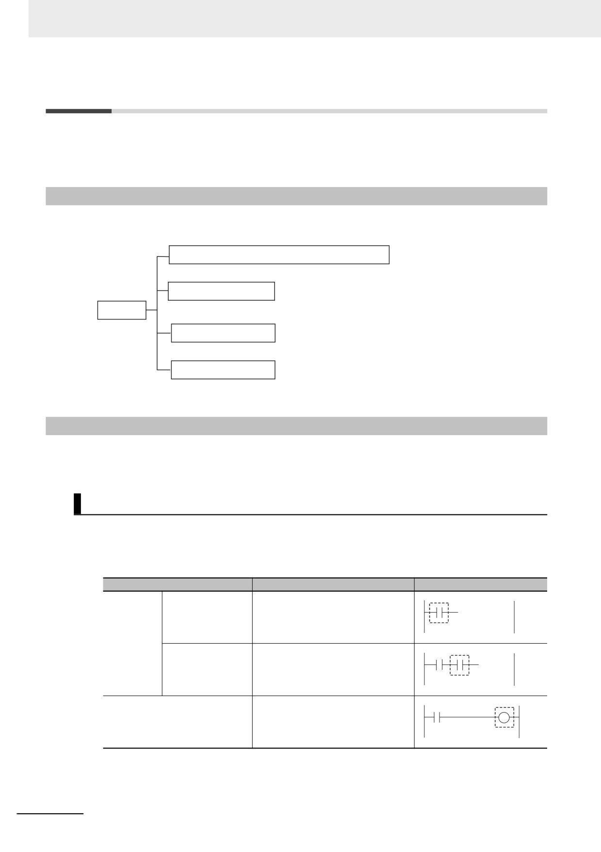
Instructions
Instructions are the smallest unit of the processing elements that are provided by OMRON for use in
POU algorithms. Instructions are classified as shown below.
Ladder diagram structure elements (inputs and outputs)
FB instructions
Instructions
FUN instructions
ST language statements
Programs, user-defined functions, and user-defined function blocks consist of these instructions.
6-6-2
Basic Understanding of Instructions
The fundamental specifications of the instructions follow the specifications of functions and function
blocks.
This section describes specifications that are unique to instructions.
Ladder Diagram Structure Elements (Inputs and Outputs)
z Locations
Instructions for ladder diagram inputs and outputs have certain positions where they can be placed,
as shown below.
Classification
Locations
Diagram
Input
Logical start
Connected directly to the left bus bar
instructions
or is at the beginning of an instruction
block.
Intermediate
Between a logical start and the output
instructions
instruction.
Output instructions
Connected directly to the right bus
bar.
6-134
6 Programming
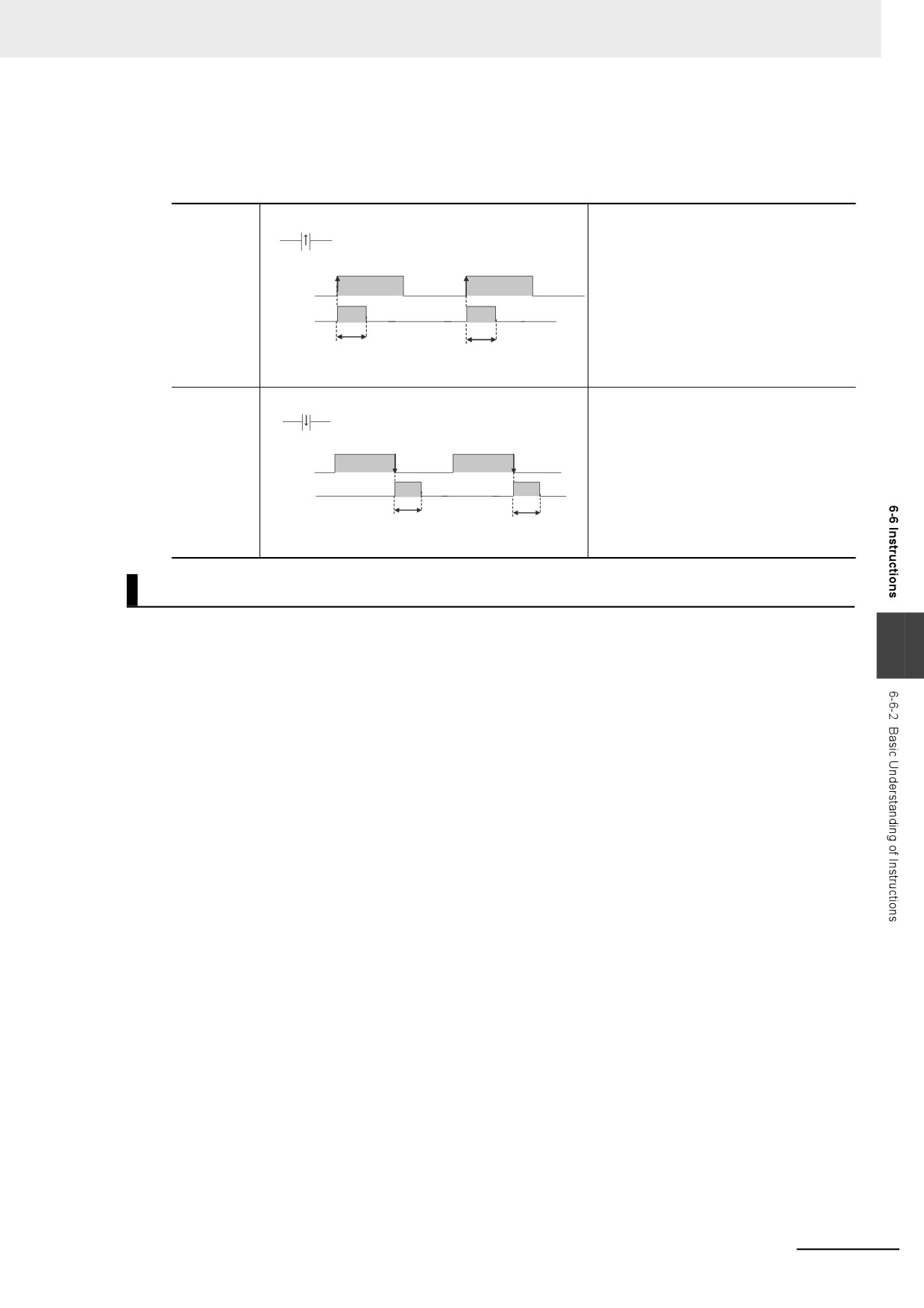
z Instruction Options
Some ladder diagram instructions for inputs also detect changes to TRUE or changes to FALSE if
you add an upward arrow or downward arrow to them.
Change to
The instruction reads input status, makes
TRUE (↑)
Variable A
comparisons, tests bits, or performs other
types of processing every task period and
outputs the power flow when result
Variable A
changes from FALSE to TRUE.
The output power flow changes to FALSE
Output
in the next task period (after it is TRUE
for one task period).
1 task period
1 task period
Time Chart
Change to
The instruction reads input status or per-
Variable A
FALSE (↓)
forms other types of processing every
task period and outputs the power flow
when result changes from TRUE to
Variable A
FALSE. The output power flow changes
Output
to FALSE in the next task period (after it
is TRUE for one task period).
1 task period
1 task period
Time Chart
Function Block Instructions
z Execution Conditions
6
The operation of the execution condition for an FB instruction depends on the instruction.
A specific input variable for the execution condition is defined for each instruction.
Examples: Execute specifies a change to TRUE or a change to FALSE in the execution condition.
Enable causes the instruction to be executed each task period according to the current
execution condition.
Function block instructions are unconditionally executed for as long as the POU that called them is
executed.
z Instruction Options
Instruction options cannot be specified.
6-135
6 Programming
FUN Instructions
z Execution Conditions
All FUN instructions have EN inputs as execution conditions. The FUN instruction is executed each
task period as long as EN is TRUE.
z Instruction Options
In a ladder diagram, you can add the following instruction options to specify a change to TRUE or a
change to FALSE as the execution condition for that instruction. ST statements do not have options.
Instruction Options
Symbol
Differentiation
Change to
@
This option creates an upwardly differentiated instruc-
option
TRUE
tion.
The instruction is executed only once when EN
changes to TRUE.
To add an instruction option, add one of the option symbols listed in the table above before the
instruction.
Example:
@ MAX
EN
ENO
In1
In2
Information That Applies to Both FB Instructions and FUN
Instructions
z Condition Flags
System-defined variables that are assigned values that represent the result of instruction processing
are called Condition Flags. The only Condition Flag for an NY-series Controller is the Carry Flag
(P_CY).
The Carry Flag serves the following purposes.
• It shows whether the result of processing an instruction exceeds the range that can be expressed
by the data type of the output variable.
• It shows whether an overflow occurred in a bit shift instruction for bit string data. For details, refer
to the NY-series Instructions Reference Manual (Cat. No. W560).
6-136
6 Programming
6-6-3
Instruction Errors
Instruction errors refer to the errors that occur when an instruction is executed. This section describes
when an instruction error occurs, which error is detected as an instruction error, and what operation fol-
low an instruction error, etc.
Timing When Instruction Errors Occur
The timing when instruction errors occur can be divided into the following three cases. Detectable
errors and operations following to the errors differ by the timing when instruction errors occur.
• When the values of input parameters or in-out parameters are checked before instruction execution.
• When internal processing is performed during instruction execution.
• When the values of output parameters are checked after instruction execution.
Errors Detected As Instruction Errors
The followings are the errors detected as instruction errors. Different errors are detected depending on
the timing when instruction errors occur.
z Errors detected before or after instruction execution
The followings are the errors detected before or after instruction execution.
• Reading or writing an array variable from or to an element beyond the array range.
• Assigning a string that is longer than the defined byte length to a STRING variable.
• Assigning a string that does not end with a NULL character to a STRING variable.
6
• Dividing an integer variable by 0.
z Errors detected during instruction execution
Errors detected during instruction execution differ by instruction. For details on errors detected in
each instruction, refer to the NY-series Instructions Reference Manual (Cat. No. W560).
6-137
6 Programming
Operation for Instruction Errors
The operation for the following elements differ depending on whether an instruction error occurs or not:
output variable ENO, output variable Error, output variable ErrorID, system-defined variable P_PRGER,
and events. The details on the operations are described below.
z
Output variable ENO, output variable Error, and output variable ErrorID
ENO (enable out), Error, and ErrorID (error code) are the output variables that indicate whether an
error exists or not. Each instruction has different output variables. The meaning of each variable and
its value on an instruction error are shown below. The values vary by the timing when an instruction
error occurs.
Value when an instruction error occurs
Output
Data
Before
During
After
Meaning
variable
type
instruction
instruction
instruction
execution*1
execution
execution*2
ENO
BOOL
TRUE
: Normal end
FALSE
FALSE
TRUE
FALSE
: Error end, Execution in prog-
ress, or Not executed
Error
BOOL
TRUE
: Error End
FALSE
TRUE
FALSE
FALSE
: Normal end, Execution in
progress, or Not executed
ErrorID
WORD
Error code on Error end, and
WORD#16#0
Error code
WORD#16#0
WORD#16#0 on Normal end
*1
If an instruction error occurs before execution of an instruction, the instruction will not be executed. There-
fore, the value of each output parameter before instruction execution will be retained.
*2
If an instruction error occurs after execution of an instruction, the instruction itself will be regarded as nor-
mally ended. Therefore, the values of output variables of the instruction will be assigned to the output
parameters. Values of the output parameter to which an error occurred are retained as the one before the
instruction execution.
z
System-defined variable P_PRGER
The system-defined variable P_PRGER is a flag that indicates the occurrence of an instruction
error. If an instruction error occurs, the value will change to TRUE regardless of when the error
occurred. When the instruction ends normally, the value will be retained.
For the details on P_PRGER, refer to Instruction Error Flag on page 6-140.
z
Events
When an instruction error occurs, an event is created for it. For details on events, refer to Events for
Instruction Errors on page 6-141.
Output Parameters in Ladder Diagrams
The following table shows the values of output parameters when an instruction, user-defined function,
or user-defined function block that is created in a ladder diagram ends normally or has an instruction
error.
Condition
Type of output parameter
Value of output parameter
Normal end
Power flow output
Values are updated according to the
BOOL parameter output
internal algorithm.
Parameter output other than BOOL
Instruction error
Power flow output
Set to FALSE.
BOOL parameter output
The previous values are retained.
Parameter output other than BOOL
6-138
6 Programming
Operation When a Syntax Error Occurs in a POU Written in ST
z
Errors in Assignment Statements
When an error occurs in an assignment statement written in ST, that line is not executed.
5
a = b / (c + d) + e ∗ f + ABS(g);
6
x := 1;
For example, if a division by zero error occurs
in (b/(c+d)) on line 5, execution of line 5 is
cancelled (the value of a is not changed) and
line 6 is executed.
This operation is the same as when the output ENO of a user-created function is FALSE.
5
a = User-created_function_block (b) + c;
6
x := 1;
When the ENO output from the user-created
function is FALSE, execution of line 5 is
cancelled (the value of a is not changed) and
line 6 is executed.
z
Errors in IF Constructs
If a syntax error occurs in ST, perform error processing for the syntax error.
When the value of (c+d), below, is zero, the lines between the IF and END_IF are not executed.
POU"AA"
6
5
IF a = b / (c + d) THEN
6
x := 1;
7
ELSE
8
x := 2;
9
END_IF;
10
y := 10;
The user must include a safety
:
:
processing for possible errors.
IF P_PRGER = TRUE THEN
x:= initial_value; (*Processing when an error occurs*)
y:= initial_value;
END_IF;
z
Syntax Errors in ST
The following syntax errors can occur in ST.
• Exceeding the number of elements in an array.
• No parameter set for in-out variable.
• STRING assignment: When the text string size (bytes) of the left side is less than the text string
length (bytes) of the right side
• Division by zero (excluding floating-point number calculations)
When the value of a floating-point number is nonnumeric, the result of the calculation will also be nonnumeric.
This is not considered an error.
z Operation for Structure Errors
The P_PRGER Flag changes TRUE and the following occurs.
Syntax
Error location
Operation
Assignment
The line is not executed.
statement
6-139
6 Programming
Syntax
Error location
Operation
IF condition
No statements between IF and END_IF are executed.
expression
CASE condition
No statements between CASE and END_CASE are executed.
expression
Control con-
FOR condition
No statements between FOR and END_FOR are executed.
structs
expression
WHILE condition
No statements between WHILE and END_WHILE are executed.
expression
REPEAT condi-
No statements between REPEAT and END_REPEAT are executed.
tion expression
Instruction Error Flag
When an instruction error occurs in a ladder algorithm or when a syntax/function error occurs in an ST
algorithm, the P_PRGER (Instruction Error Flag) system-defined variable changes to TRUE. The
P_PRGER flag is a local variable for the program. This flag changes to TRUE when an instruction error
occurs in the program, and remains TRUE during the next task period.
Read
Variable
Data
Meaning
Function
Range of values
Initial value
/writ
name
type
e
P_PRGER
Instruction Error Flag
This flag changes to and
BOOL
TRUE or FALSE
FALSE
Read
remains TRUE when an
/write
instruction error occurs. After
this flag changes to TRUE, it
stays TRUE until the program
changes it back to FALSE.
The user can write the P_PRGER Flag. You can temporarily set the value of this flag to FALSE through
a user operation to determine if the error occurs within a specific range, for example. After this flag
changes to TRUE, it remains TRUE until the operating mode is changed or the flag is overwritten by a
program.
Example:
User Program
P_PRGER
Initial process
R
If the flag is ON, you
Algorithm (instructions)
know that the
Normal process #1
instruction error has
to be inside this
range.
P_PRGER
Error processing
Normal process #2
for normal
process #1
Example: Initial values
set for variables
The P_PRGER Flag also changes to TRUE when an instruction error occurs inside a user-defined
function block that is used by the program.
Example:
Program
P_PRGER : OFF
Inside function block definition
User-defined
P_PRGER : OFF
function block
Instruction error
P_PRGER : ON
P_PRGER : ON
6-140
6 Programming
Events for Instruction Errors
When an instruction error occurs, an event is created for it. Refer to 8-5 Event Logs for the procedure to
check events. For information on the events that are created, refer to the NY-series Instructions Refer-
ence Manual (Cat. No. W560).
Precautions for Correct Use
• To create events for instruction errors, you must select Use for Event Log Settings − Instruc-
tion Error Output on the Sysmac Studio. Refer to 4-2-2 Controller Setup and to the Sysmac
Studio Version 1 Operation Manual (Cat. No. W504-E1-04 or later) for information on the Con-
troller Setup.
• If you change the user program after an instruction error occurs, the information in the event
log may no longer be correct.
• If an instruction with an error is executed repeatedly, an instruction error or event is created
each time the instruction is executed. This may cause the event log to exceed the maximum
number of events. If this occurs, older events are overwritten.
Additional Information
• If an error occurs in a motion control instruction, two events are created, one for the instruction
error and one for the motion control instruction. For details on events for motion control
instructions, refer to the NY-series Motion Control Instructions Reference Manual (Cat. No.
W561).
• Events for motion control instruction are created even if you select Do not use for Event Log
Settings − Instruction Error Output in the Controller Setup on the Sysmac Studio.
6
6-141
6 Programming
6-7
Namespaces
This section provides the specifications for namespaces and the procedures to use them. Refer to the
Sysmac Studio Version 1 Operation Manual (Cat. No. W504-E1-03 or later) for the procedures to
manipulate them.
6-7-1
Namespaces
Namespaces are a system for grouping function block definitions and other entities to manage them in
nested structures. They are similar to grouping files in folders to manage them in a directory structure. If
you do not use namespaces, the name of each function block definition or other entity must be unique.
If you use namespaces, you can use the same name more than once by setting namespaces. Using
namespaces is not required.
Features of Namespaces
Namespaces provide the following features.
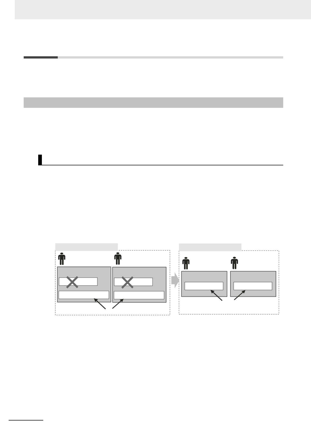
z Preventing Duplicated Names
As long as different namespaces are used, you can use the same name for a function block or other
entity more than once. For example, assume that several systems must be programmed, and that a
different programmer will program each of them. Here, it would be likely that the same names would
be used for different function block definitions or other entities. If you did not use namespaces, you
would have to create naming rules to prevent the duplication of names. However, if you set a differ-
ent namespace for each system, programming would be possible without worrying about duplicating
names with other systems.
Not Using Namespaces
Using Namespaces
Programmer for
Programmer for
system A
system B
Programmer for
Programmer for
system A
system B
Namespace: None
Namespace: None
Namespace: System_A
Namespace: System_B
FB: Read_recipe
FB: Read_recipe
FB: Read_recipe
FB: Read_recipe
FB: System_A_Read_recipe
FB: System_B_Read_recipe
The same names can be used.
All names must be unique, so naming rules must be followed.
6-142
6 Programming
6-7-2
Namespace Specifications
This section describes what namespaces can be used for, namespace notation, and namespace decla-
rations.
Namespace Usage
You can use namespaces for the entities that are listed in the following table. You cannot use them for
local variables.
Library object
Details
POU definitions
Function definition names and function block definition names
Data types
Structure data type names, union data type names, and enumeration data
type names
Namespace Notation
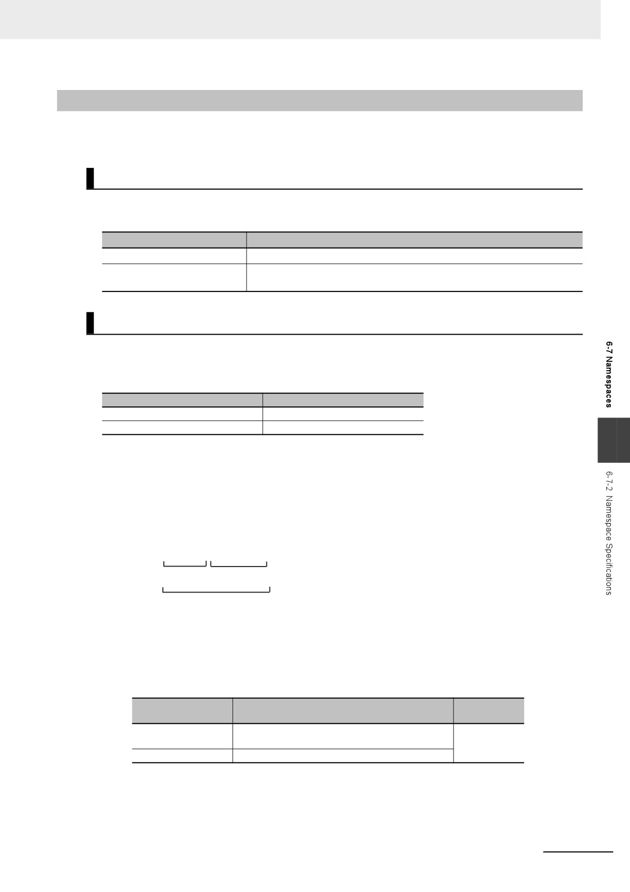
Separate the levels in a namespace with backslashes (\). To use a namespace in a POU algorithm,
place two backslashes (\\) at the front of the namespace.
Examples:
Location of namespace
Expression
Outside of an algorithm
System_A\Read_recipe
Inside of an algorithm
\\System_A\Read_recipe
6
z Fully Qualified Names and Short Names
The fully qualified name of an entity is the name that includes the name of the namespace. The
short name of an entity is the name that does not include the name of the namespace.
In the algorithm in a POU definition, you can use the short name of any POU definition that has the
same namespace as the POU definition of the algorithm.
Example:
System_A\Read_recipe
Name of
Short name
namespace
Fully qualified name
z Restrictions on Namespace Notation
• You can use the same characters as you can for variable names. For details, refer to 6-3-12
Restrictions on Variable Names and Other Program-related Names.
• The following table gives the limits to the number of characters in the names of namespaces.
Character
Name
Maximum size
encoding
Names of name-
93 bytes
UTF-8
spaces
Short names
127 bytes
6-143
6 Programming
Precautions for Correct Use
•
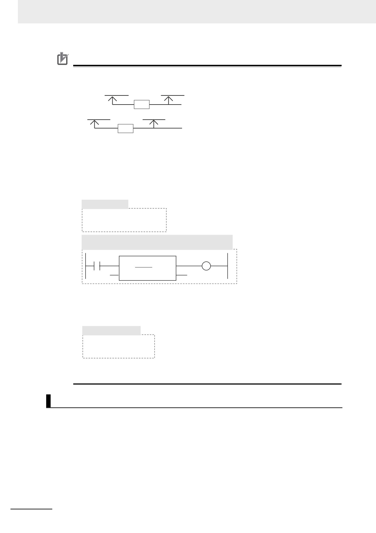
An error will occur when you build the program if the short name of a variable is also used in
the name of the namespace.
System_A\Process_A\Read_recipe\Process_A
Not
The short name is used in the name of the namespace.
allowed.
System_A\Read_recipe\System_A\Process_A
Not
The same name is used twice within the overall name of
allowed.
the namespace.
•
You can use the short name of a POU definition in the algorithm of a POU definition if it is in
the same namespace. However, an error will occur when you build the program if there is a
POU definition or data type with the same short name at a higher level in that namespace.
For example, assume that the following POU definitions are used. You can use the short name
to call System_A\Read_recipe\Process_A from within the algorithm of the Process_B function
block definition (which is in the System_A\Read_recipe namespace) because Process_A is in
the same namespace.
POU Definitions
System_A\Read_recipe\Process_A
System_A\Read_recipe\Process_B
Notation in the Algorithm of the
System_A\Read_recipe\Process_B Function Block Definition
Process_A
If, however, a System_A POU definition also exists at a higher level than the Sys-
tem_A\Read_recipe namespace, “Process_A” exists twice. Therefore, an error will occur
when you build the program.
In this case, you must use the fully qualified name or change the short name.
POUPOU Definitions
Process_A (no namespace)
System_A\Process_A
• If any names are the same as a reserved word, an error will occur when you check the pro-
gram.
Namespace Declarations
To program with namespaces, you can declare the namespaces in advance before you use them in the
algorithm of a POU definition.
After you declare the namespace in the POU definition, you can use the short name of any POU defini-
tion or other entity that has the same namespace. You can also use the fully qualified name even if you
declare the namespace.
In the algorithm in a POU definition, you can use the short name of any function definition or function
block definition that has the same namespace as the POU definition of the algorithm even if you do not
declare the namespace.
You can declare more than one namespace for the same POU definition.
6-144
6 Programming
z Notation Examples
Notation examples are provided below for creating a function block definition when declaring the name-
spaces to use in the function block definition and when not declaring the namespaces.
Examples:
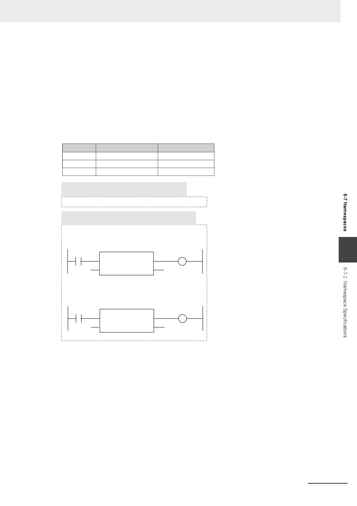
In this example, the Read_recipe and Calculate_upper_limit function block definitions are used in the
algorithm for the Lifter function block definition. Each of these function block definitions is in a different
namespace. In the Lifter function block definition, only the System_C namespace is declared. The fully
qualified name must be given for the Read_recipe function block, which is not in the System_C name-
space. The short name can be given for the Calculate_upper_limit function block, which is in the Sys-
tem_C namespace.
Namespace
Entity
Short name
System_A
Function block definition
Lifter
System_B
Function block definition
Read_recipe
System_C
Function block definition
Calculate_upper_limit
The following notation is used in the namespace
declaration for the Lifter function block definition.
System_C
Notation for the Algorithm of the Lifter Function Block
Definition
• When Namespace Is Not Declared
The System_B namespace of the Read_recipe function
block definition is not declared, so you must give the fully
qualified name.
6
\\System_B\Read_recipe
• When Namespace Is Declared
The System_C namespace of the Calculate_upper_limit
function block definition is declared, so you can give the
short name.
Calculate_upper_limit
z Restrictions of Declarations
• You can use short names only in the algorithm of a POU definition.
6-145
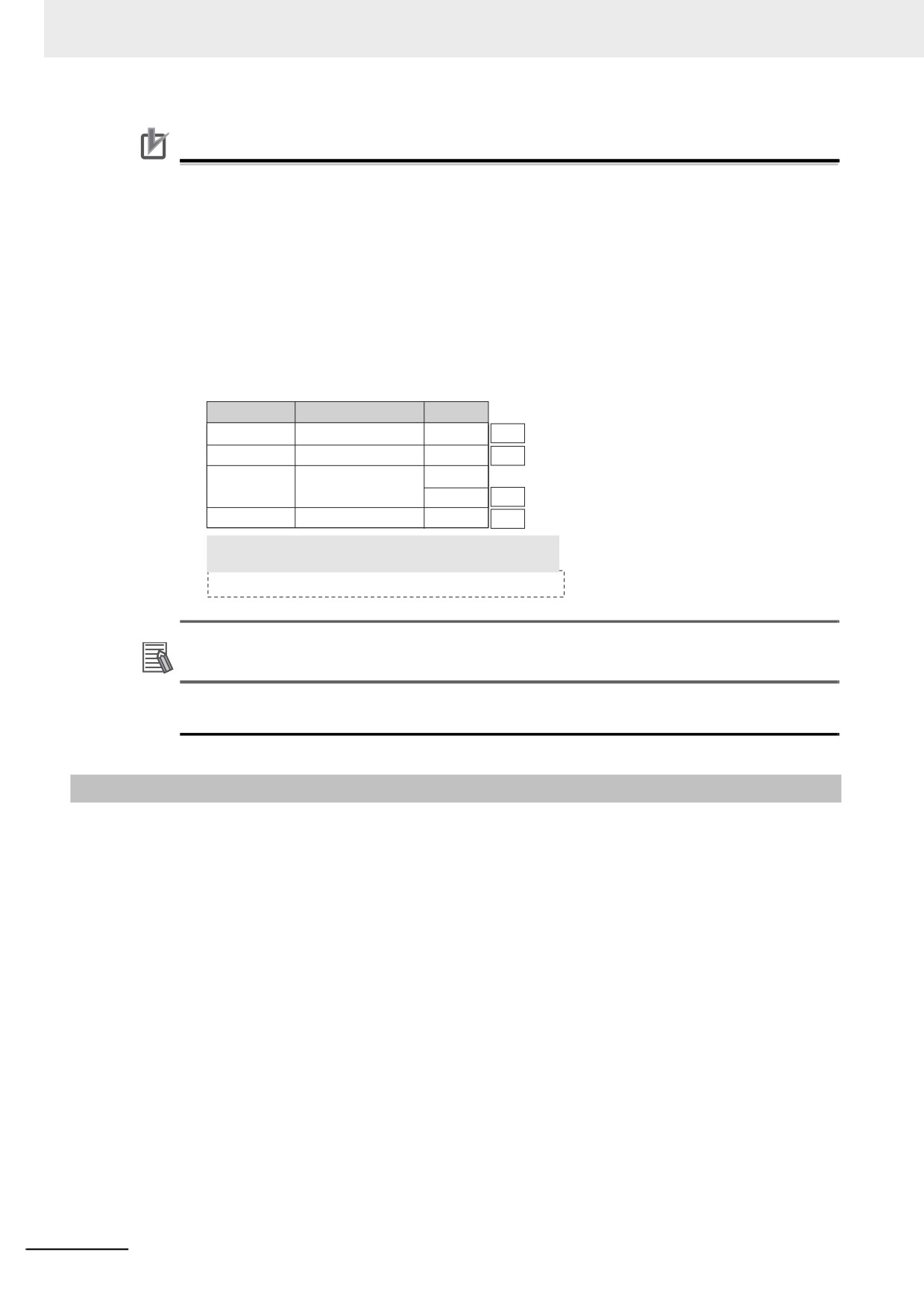
6 Programming
Precautions for Correct Use
• An error is detected during the program check in the following cases.
• If a namespace that does not exist is declared
• If you declare more than one namespace for one POU definition, and a POU definition, data
type, or other entity with the same name exists in two or more namespaces
• An error will occur when you build the program if the same name is used as follows for differ-
ent POU definitions or data types.
• If the same name is used for the namespace of a POU definition and at a higher level in the
namespace
• If the same name is used in a declared namespace
• If the same name is used without a namespace
Namespace
Entity
Short name
Not
System_A\Lifter
Function block definition
Process_A
allowed.
The name is used in the namespace of the POU definition.
Not
The name is used at a higher level than the namespace
System_A
Function block definition
Process_A
allowed.
of the POU definition.
System_B
Function block definition
Process_B
Not
Process_A
allowed.
The name is used in a declared namespace.
Not
None
Function block definition
Process_A
allowed.
The name is used without a namespace.
The following notation is used in the namespace
declaration for the Process_A function block definition.
System_B
Additional Information
You cannot set a namespace for a program name. However, you can declare namespaces for
objects that are used in the algorithm of the program.
6-7-3
Procedure for Using Namespaces
Use the Sysmac Studio to set the namespaces and then declare them. Perform steps 1 and 2 when you
create data types or when you create function definitions, function block definitions, or other objects.
Declare a namespace with step 3 to use an object for which a namespace is set.
1 In the Data Type Editor, set the namespace for the data type.
2 Set the namespace in the properties of the function definition or function block definition.
3 In the Ladder Editor or ST Editor, declare the namespace in the properties of the function defini-
tion or function block definition.
4 Use the data types, function definitions, and function block definitions in the user program.
Refer to the Sysmac Studio Version 1 Operation Manual (Cat. No. W504-E1-03 or later) for specific
procedures.
6-146
6 Programming
6-8
Libraries
This section describes the specifications of libraries. Refer to the Sysmac Studio Version 1 Operation
Manual (Cat. No. W504-E1-03 or later) for specific procedures.
6-8-1
Introduction to Libraries
A library contains POU definitions and data types in a form that allows you to reuse them as objects in
programming. The objects in a library are called library objects.
The NY-series Controller allow you to create and use libraries.
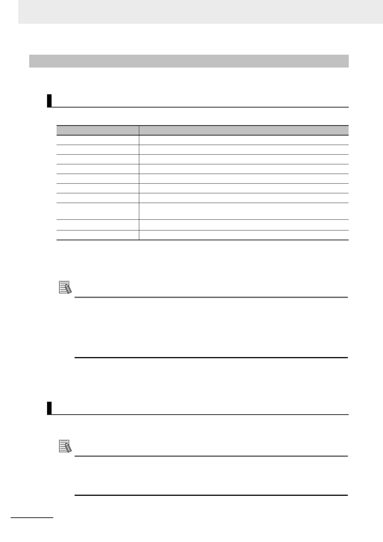
The following figure illustrates the use of library objects. Here, program A uses FUN:A1 and FB:B1 from
the objects in the library, and program B uses Type:C1 and FB:B1.
Library
Sysmac Studio
Library objects
Create library.
FUN:A1
FB:B1
FUN:A2
FB:B2
Type:C1
FB:B3
Type:C2
6
Reuse objects.
FUN:A1
Type:C1
FB:B1
FB:B1
Program A
Program B
6-147
6 Programming
6-8-2
Specifications of Libraries
This section describes the library settings and synchronization.
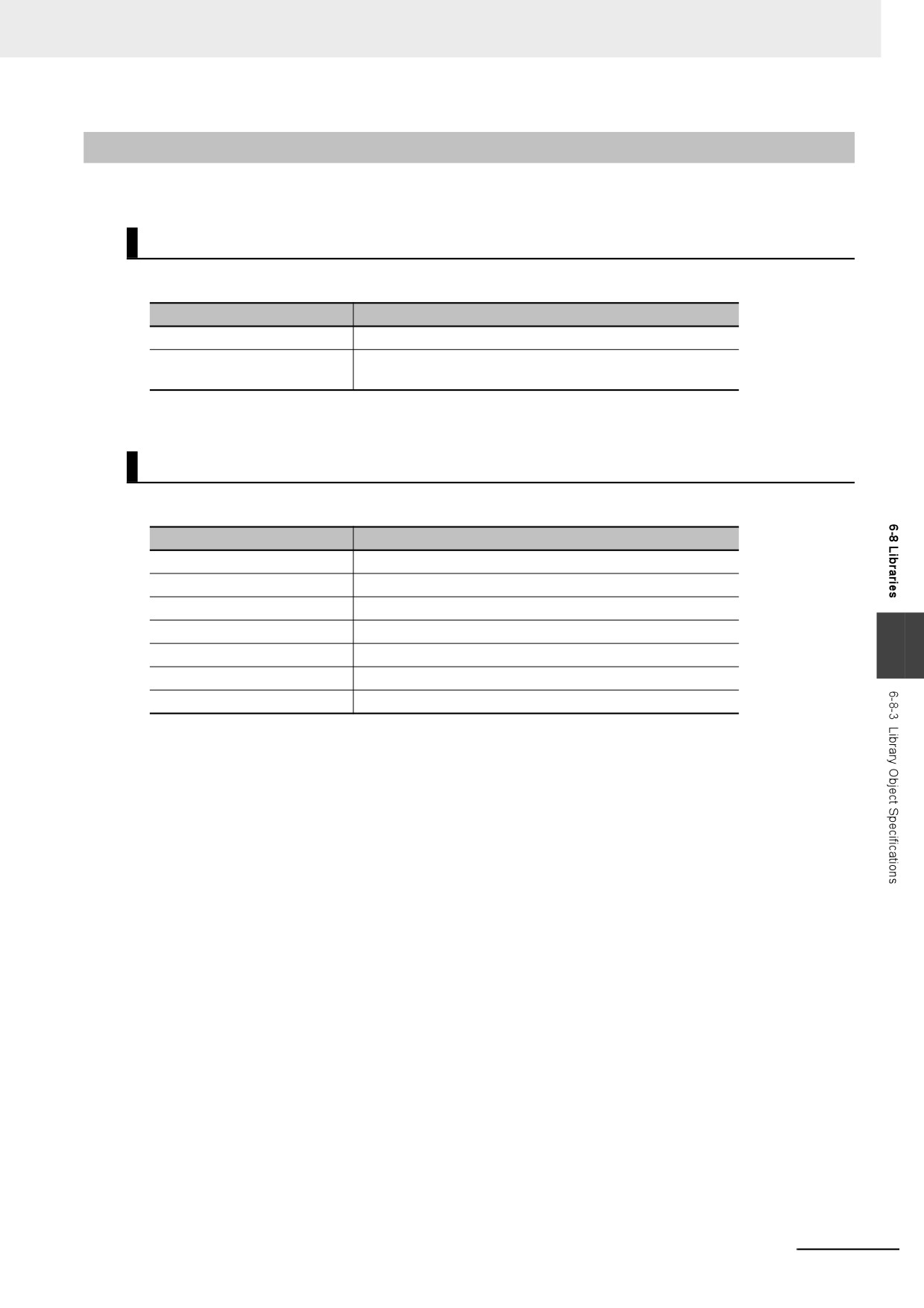
Library Settings
The following settings are supported for libraries.
Setting
Description
Name
The name of the library.
Version
The version of the library.
Author
The creator of the library. (optional)
Creation date
The date that the library was created.
Update date
The date that the library was last updated.
Comment
A comment on the library. (optional)
Company name
The name of the company that created the library. (optional)
ID
A unique ID that is used to access the library. The ID is generated automatically.
You cannot change it.
Display/hide source
You can specify whether to display or hide the source.*
Attached files
You can attach one or more files.
* If data protection is set for a library object, a password is required to display the source code.
You can also access other libraries to create library objects. When you do, you can select whether to
include the library data from the accessed library.
Additional Information
When you select to include accessed library data, the accessing library is created so that it con-
tains a copy of the accessed library data. This means that only one library file is required. How-
ever, if there is more than one accessing library, you must change each one of them to make any
changes. When you select not to include accessed library data, the accessing library is created
without the accessed library data. This means that there will be two library files, the accessing
file and the accessed file. However, even if there is more than one accessing library, you need to
change only the accessed library to make changes.
z Selecting Library Objects
You can select the objects to include in a library.
Library Synchronization
You can download a library to a Controller, upload a library from a Controller, or verify a Controller
library against one on the computer.
Additional Information
• If you transfer a project for which transferring the source program is disabled from the Sysmac
Studio to a Controller that contains libraries for which the source is displayed, the source data
for the library is not transferred.
• The libraries in the Controller are deleted for the Clear All Memory operation.
6-148
6 Programming
6-8-3
Library Object Specifications
This section describes the library objects that can be created and the settings for the library objects.
Applicable Library Objects
You can handle the following entities as library objects.
Library objects
Details
POU definitions
Functions and function blocks
Data types*
Structure data types, union data types, and enumeration
data types
* Data types are always included in the library object selections on the Sysmac Studio.
Library Object Settings
You can set the following for each library object.
Property
Definition
Name
The name of the library object.
Namespace
The namespace of the library object.
Version*
The version of the library object.
Author*
The creator of the library object. (optional)
6
Creation date*
The date that the library object was created.
Update date*
The date that the object library was last updated.
Comment
A comment on the library object. (optional)
* These items can be set only for functions and function blocks. They are set in the POU definition properties on
the Sysmac Studio.
6-149

6 Programming
6-8-4
Procedure to Use Libraries
Use the following procedures to create and use libraries.
Procedure to Create Libraries
Create a project to use as the library. Use the following procedure to create and save a library.
1 Create a library project.
When you create the project, select a library project as the project type in the Project Window.
2 Create library objects.
In the library project, create the required POU definitions and data types, and then check them
to make sure that they operate correctly.
3 Set the properties of the library.
Set the properties of the library project, including selecting the library objects, hiding/displaying
source code, and attached files.
4 Save the project as a library file.
Save the project in a library file in the Create Library File Dialog Box.
Additional Information
• You can change an existing project to a library project as long as the only device that is regis-
tered in the project is a Controller. Simply change the project type in the project properties to a
library project.
• You can create data that cannot be used as library objects in a library project. However, you
cannot select any of this data as library objects.
• We recommend that you use namespaces for names of the functions, function block defini-
tions, and data types that you create as library objects to prevent duplicating names with other
libraries. For details on namespaces, refer to 6-7 Namespaces.
Procedure to Use Libraries
You can read objects that are created in libraries into a project to use them in the user program. Use the
following procedure to use libraries.
1 Specify the library.
Specify the library file to access in the Library Reference Dialog Box of the project in which to
use the library objects.
2 Use the library objects in programming.
Use the library objects from the library that you read in the project. Use the library objects in the
same way as any other functions, function block definitions, or data types.
6-150
6 Programming
6-9
Programming Precautions
This section describes precautions for developing a user program.
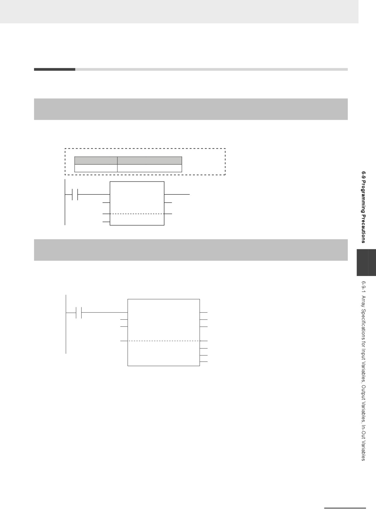
6-9-1
Array Specifications for Input Variables, Output Variables, In-Out
Variables
Some instructions handle array variables.
Example:
Data Type Table
Variable name
Data type
data
ARRAY[0..4] OF INT
SetBlock
EN
ENO
INT#0
In
Out
AryOut
data[0]
data[0]
UINT#5
Size
6-9-2
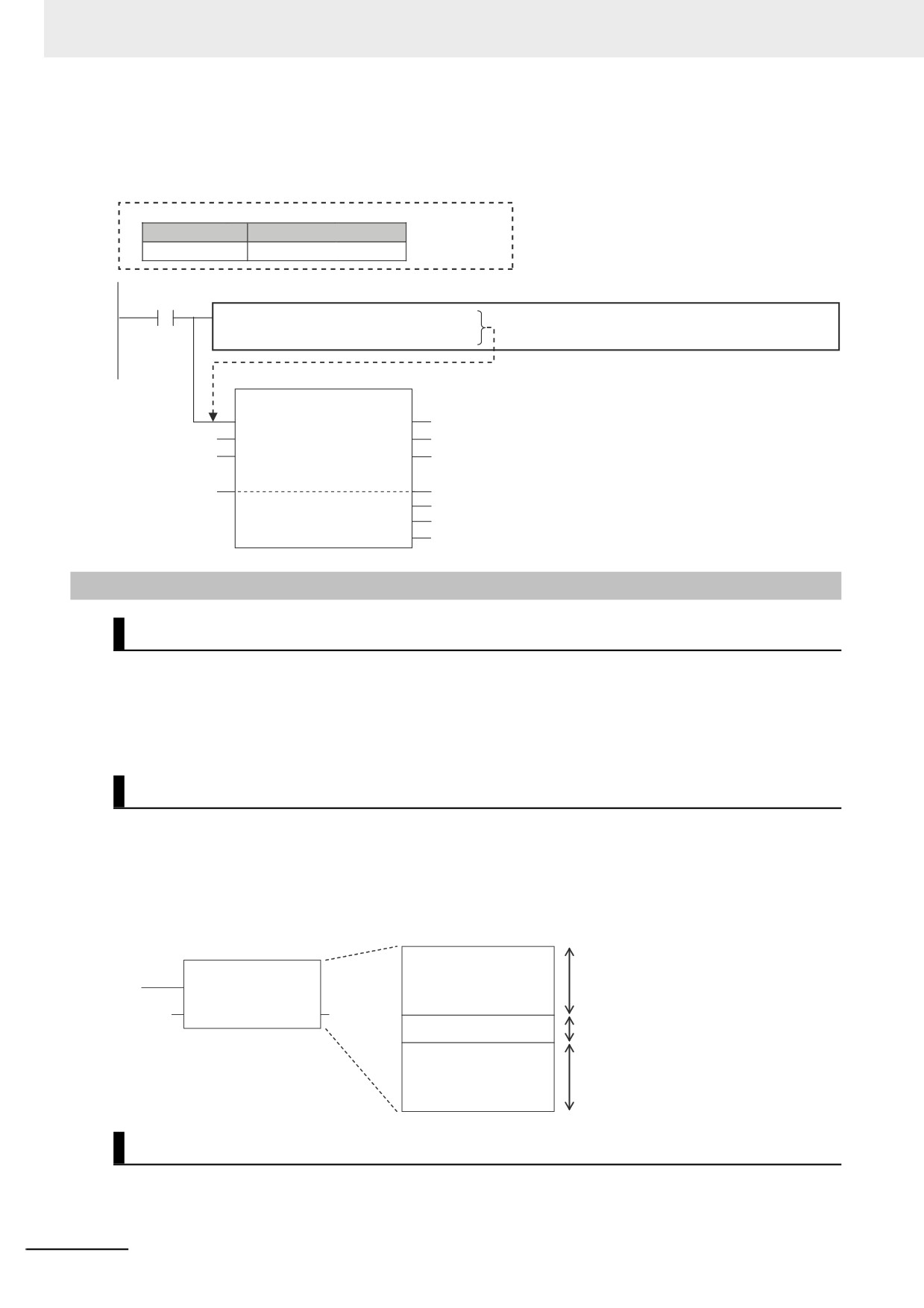
Structure Variables for Input Variables, Output Variables, In-Out
Variables
6
Some instructions have structure variables for input, output, or in-out variables.
Example:
SerialRcv_instance
Operating
SerialRcv
Execute
Done
InPort
Port
Busy
UINT#13
Size
Error
DstDat
RecvDat[0]
RecvDat[0]
ErrorID
ErrorIDEx
RcvSize
RecvSize
6-151
6 Programming
In this case, you must create a structure variable for the input, output, and in-out parameters, then use
the MOVE instruction to set the values.
Example:
Variable Table
Variable name
Data type
InPort
_sPORT
Execution
Inline ST: Sets values in the Inport structure variable.
condition
1 InPort.UnitNo
:=_CBU_No00;
// Serial Communications Unit with unit number 0
2 InPort.PhysicPortNo
:=USINT#2;
// Serial port 2
SerialRcv_instance
SerialRcv
Execute
Done
InPort
Port
Busy
UINT#13
Size
Error
DstDat
RecvDat[0]
RecvDat[0]
ErrorID
ErrorIDEx
RcvSize
RecvSize
6-9-3
Master Control
Introduction
Master control is used to make output FALSE for all processing between the MC (Master Control Start)
instruction and the MCR (Master Control End) instruction. Master control is useful to control the execu-
tion conditions of a relatively long series of instructions.
Refer to information on the MC and MCR instructions in the NY-series Instructions Reference Manual
(Cat. No. W560) for details.
Master Control Programming Languages
You can use master control in ladder diagrams.
You cannot use master control with ST. You also cannot use master control for inline ST inside a ladder
diagram.
Example:
Inside a Master Control Region:
Ladder diagram algorithm
The ladder diagram is reset by the master
Programs
control.
For example, the output variables from OUT
User-defined
instructions change to FALSE.
function block
Nothing is done.
Inline ST
Ladder diagram algorithm
The ladder diagram is reset by the master
control.
For example, the output variables from OUT
instructions change to FALSE.
Operation of Instructions That Are Reset in a Master Control Region
Refer to information on the MC and MCR instructions in the NY-series Instructions Reference Manual
(Cat. No. W560) for the operation of other instructions in the master control region when master control
is reset.
6-152
Checking Operation and Actual Operation
This section describes the items and procedures for checking the operation of an
NJ/NX-series Controller, including offline debugging procedures.
7-1
Overview of Steps in Checking Operation and Actual Operation
7-2
7-2
Offline Debugging
7-3
7-2-1
Features of Simulation
7-3
7-2-2
Simulation Execution
7-3
7-2-3
Setting Up Simulations
7-6
7-3
Checking Operation on the Actual System and Actual Operation
7-8
7-3-1
Procedures
7-8
7
7-3-2
Downloading the Project
7-9
7-3-3
Checking I/O Wiring
7-9
7-3-4
MC Test Run
7-9
7-3-5
Checking the Operation of the User Program
7-10
7-3-6
Starting Actual Operation
7-10
7-1