Omron IPC Machine Controller Industrial Panel PC / Industrial Box PC. Software User’s Manual (Industrial PC Platform NY-series) - page 13
8 Controller Functions
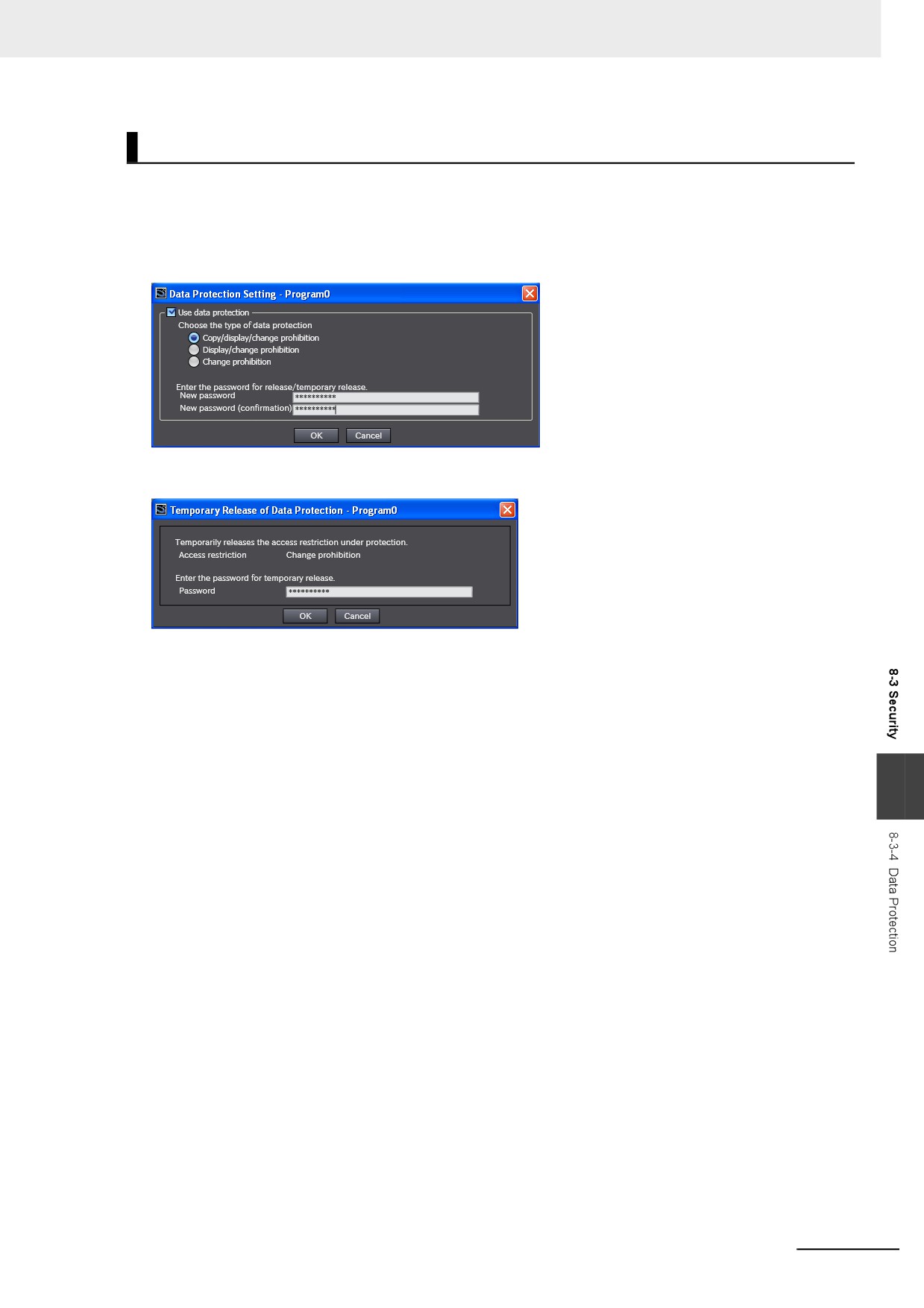
Operating Procedure
This function is used when the Sysmac Studio is offline. The settings are saved in the project file. When
you use the synchronization function of the Sysmac Studio to transfer the project, the data protection
settings in the data in the computer or Controller are transferred to Controller or computer.
Select Security − Set/Release Data Protection from the Controller Menu of the Sysmac Studio to set
protection.
Select Security − Temporarily Change Prohibition of Data Protection from the Controller Menu
of the Sysmac Studio to temporarily clear protection.
Select Security − Finish Temporary Change Prohibition of Data Protection from the Controller
Menu of the Sysmac Studio to end temporary change protection.
Refer to the Sysmac Studio Version 1 Operation Manual (Cat. No. W504) for specific procedures.
8
8-23
8 Controller Functions
8-3-5
Operation Authority Verification
Introduction
Online operations are restricted by operation rights to prevent damage to equipment or injuries that
may be caused by operating mistakes. Examples are shown below.
• I/O Monitor: Writing, forced refreshing, etc.
• Controller operations: Changing the operating mode, online editing, MC Test Run, etc.
You can register passwords for operation authority for each Controller in the Sysmac Studio. If a correct
password is entered when an online connection is made to a Controller, the online operations for the
operation authority category for the password that was entered will be allowed.
The Administrator sets a password for each operation authority. Users are notified of the operation
authority name and password according to their skills.
Refer to the Sysmac Studio Version 1 Operation Manual (Cat. No. W504) for specific operating proce-
dures for operation authorities.
Operation
For operation authority verification, select Security − Setting of Operation Authority from the Control-
ler Menu on the Sysmac Studio.
Refer to the Sysmac Studio Version 1 Operation Manual (Cat. No. W504) for specific procedures.
8-24
8 Controller Functions
Specifications
z
Types of Operation Authorities
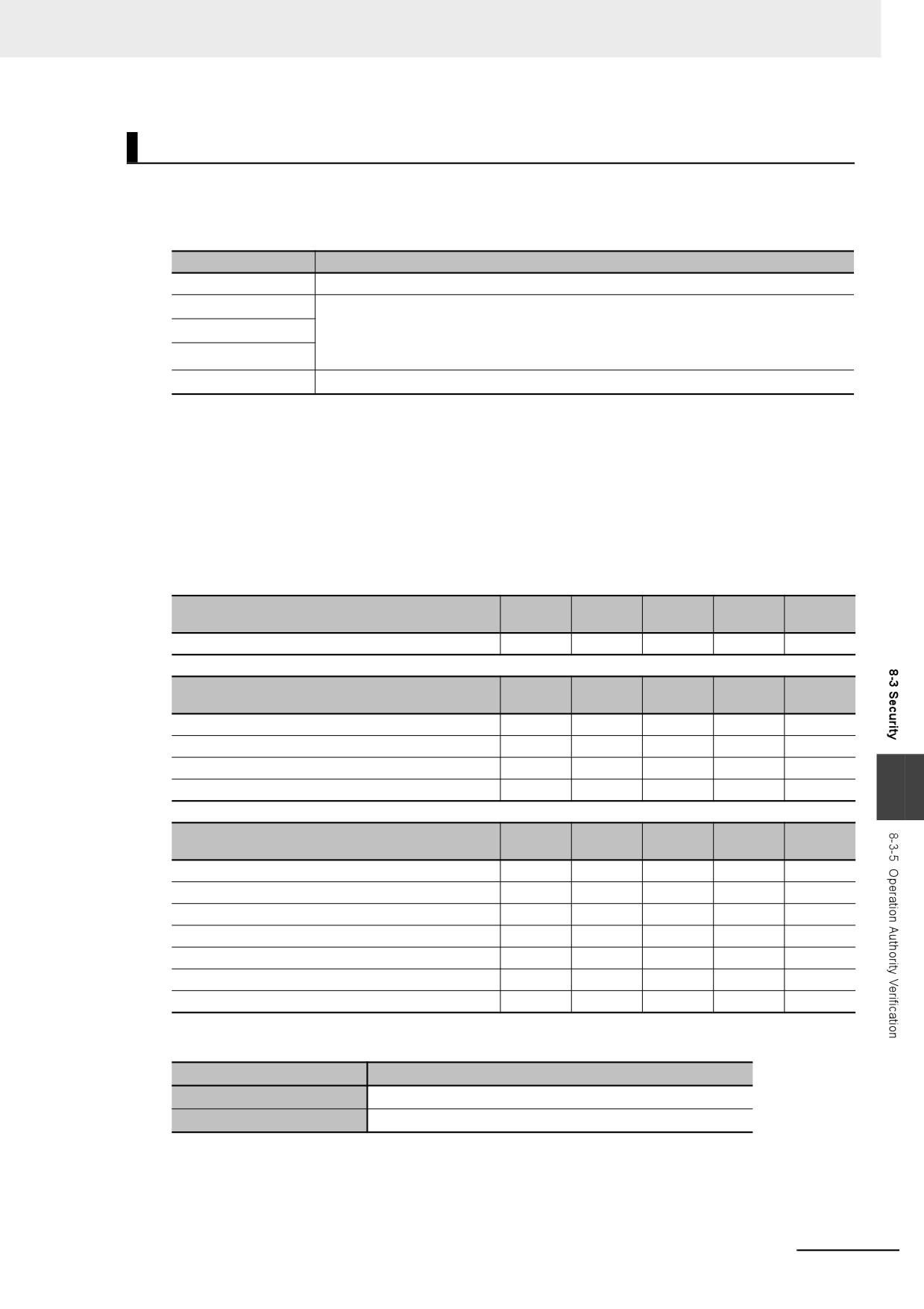
You can use the following five operation authorities on the Sysmac Studio. They are given in
descending order of authority.
English name
Password
Administrator
Required.
Designer
Optional*1
Maintainer
Whether a password is required is determined by the default operation authority that is set in the
Setting of Operation Authority Dialog Box. The default operation authority is used when a pass-
Operator
word is not input.
Observer
Not required.
*1
Whether a password is required is determined by the default operation authority that is set in the Setting of
Operation Authority Dialog Box. A password must be entered to perform operations that require an operation
authority that is higher than the default operation authority. A password is not required to perform operations
that require an operation authority that is equal to or lower than the default operation authority.
z
Examples of Online Operations for Operation Rights
Examples of the online operations that are allowed for each operation authority are given below.
Refer to the Sysmac Studio Version 1 Operation Manual (Cat. No. W504) for details.
OK: Operation possible, VR: Verification required for each operation, NP: Operation not possible
Adminis-
Main-
Status monitor (example)
Designer
Operator
Observer
trator
tainer
Monitoring errors for troubleshooting
OK
OK
OK
OK
OK
Adminis-
Main-
I/O monitor operations (examples)
Designer
Operator
Observer
trator
tainer
I/O monitor: Reading
OK
OK
OK
OK
NP
I/O monitor: Writing
OK
OK
OK
VR
NP
Controlling BOOL variables
OK
OK
OK
VR
NP
Forced refreshing
OK
OK
OK
NP
NP
8
Adminis-
Main-
Controller operations (examples)
Designer
Operator
Observer
trator
tainer
RUN mode/PROGRAM mode
OK
OK
VR
NP
NP
Online editing
OK
OK
VR
NP
NP
Resetting the Controller
OK
OK
NP
NP
NP
Resetting errors (troubleshooting)
OK
OK
OK
VR
NP
Starting or restarting an MC Test Run
OK
OK
VR
NP
NP
User program execution IDs for Controllers
OK
NP
NP
NP
NP
CPU Unit write-protection
OK
OK
OK
NP
NP
z
Password Specifications
Item
Description
Valid number of characters
8 to 32
Applicable characters
Single-byte alphanumeric characters (case sensitive)
8-25
8 Controller Functions
8-3-6
CPU Unit Write Protection
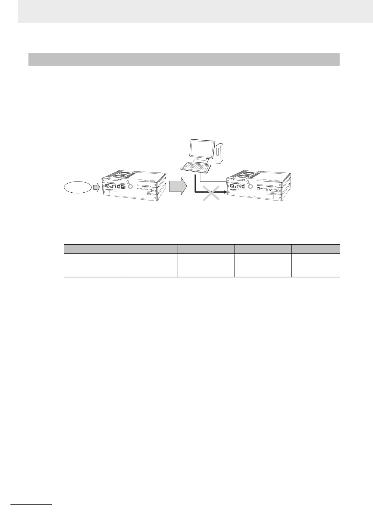
This function disables the ability to write data to Controller to protect user program assets and prevent
misuse.
z Controller Write Protection at Startup
This setting automatically enables write protection when you turn ON the power supply to the Con-
troller.
Sysmac Studio
Controller
Controller
At startup
Write protection
Write Protection
Writing is not
possible.
Set whether to automatically enable write protection when the power supply is turned ON in the
Operation Settings under Configurations and Setup − Controller Setup of the Sysmac Studio.
Access point
Setting group
Setting
Description
Set values
Operation Settings,
Security Settings
Write Protection at
Sets whether to
Do not use.
Operation Settings
Startup
enable write protec-
Use.
Tab, Basic Settings
tion.
z Setting and Removing Write Protection from the Sysmac Studio
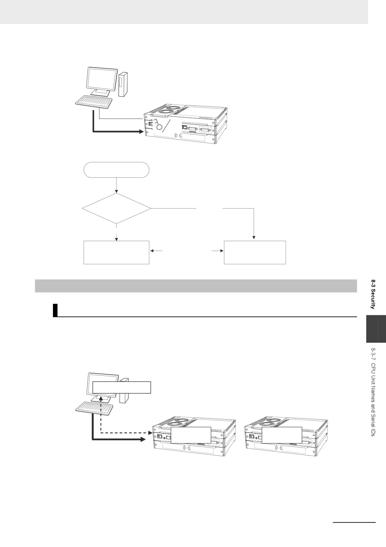
In the Sysmac Studio, go online and select Security − CPU Unit Write Protection from the Control-
ler Menu to toggle write protection.
8-26
8 Controller Functions
Sysmac Studio
Controller
None
You can turn write
protection ON and
OFF.
When power is turned ON
Not
Write protection
enabled.
set?
Enabled
Changed from the
Writing disabled.
Writing enabled.
Sysmac Studio.
8-3-7
CPU Unit Names and Serial IDs
Introduction
Register a CPU Unit name in the Controller. When going online to a Controller from the Sysmac Studio,
8
the CPU Unit name in the project is compared to the name of the Controller being connected to. This
helps prevent incorrect connections to the Controller from the Sysmac Studio. It is particularly effective
for operations performed over an EtherNet/IP network.
Sysmac Studio
CPU Unit
name: A
Controller
Controller
CPU Unit
CPU Unit
name: A
name: B
A check is performed
to see if the CPU Unit
name matches for
online connections.
In addition to the CPU Unit name, it is also possible to use serial ID identification based on the Control-
ler production information (optional).
8-27
8 Controller Functions
Setting Methods
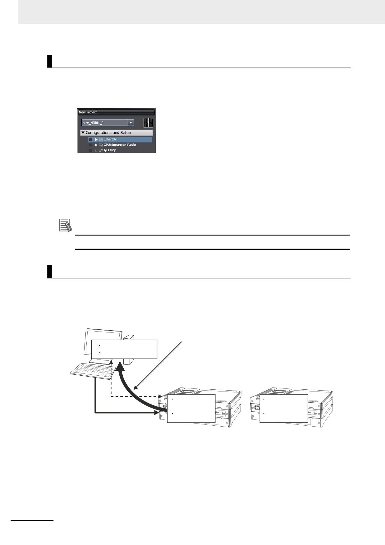
1 Set the CPU Unit name when you create a project on the Sysmac Studio.
The CPU Unit name is displayed as shown below.
To change the name, right-click the Controller icon and select Rename.
2 When you first connect to the Controller online, the Sysmac Studio prompts you to store the
CPU Unit name in the Controller.
3 After that, when you connect to the Controller online, the Sysmac Studio refers to the CPU Unit
name in the project and the CPU Unit name of the Controller you connect to. A warning dialog
box is shown if they do not match, and you are asked whether to continue to connect.
Additional Information
You can name EtherNet/IP ports in the Network Configurator.
Serial IDs
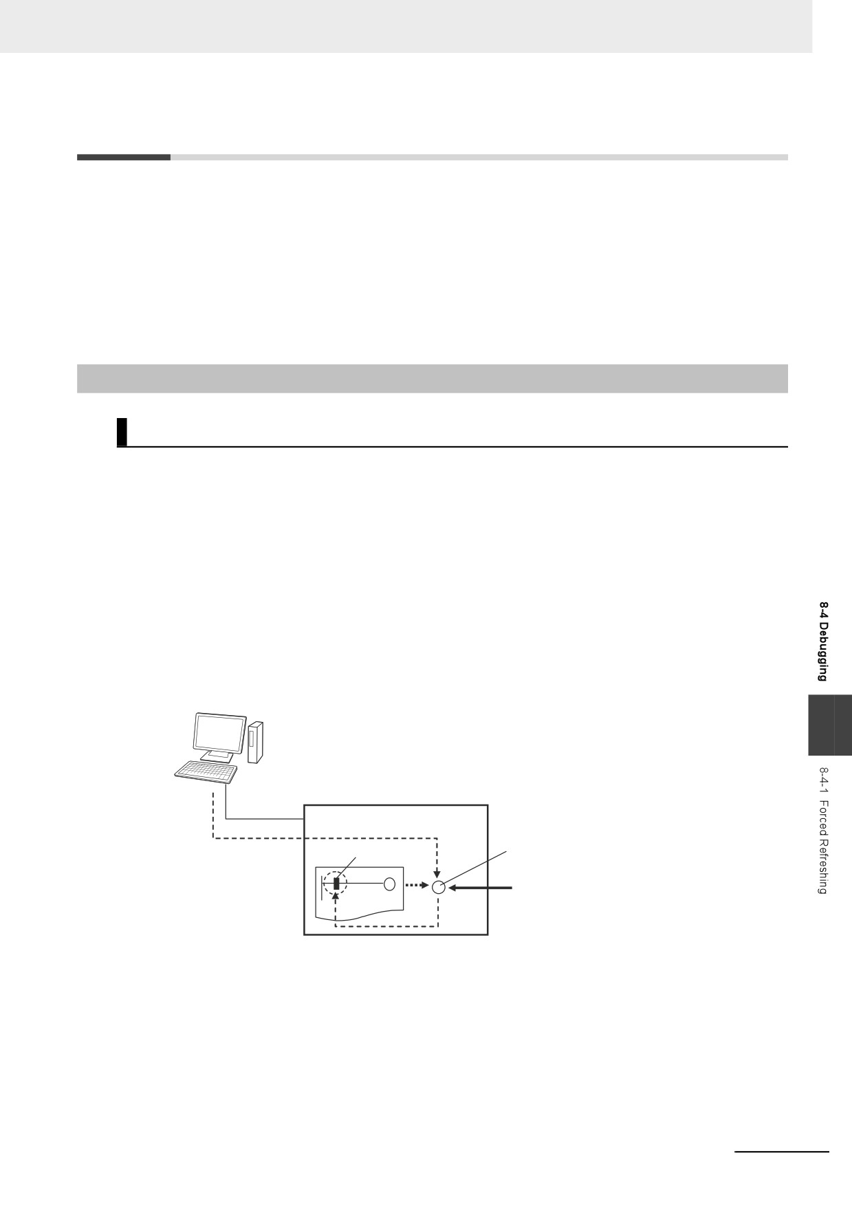
When the Sysmac Studio first connects online, you can obtain the serial ID from the Controller’s pro-
duction information and store it in the project. After that, when the Sysmac Studio connects online, both
the CPU Unit name and the serial ID are compared. This enables stricter verification of the Controller.
Sysmac Studio
1.
When you connect online, the serial ID is
CPU Unit name: A
obtained from the Controller.
Serial ID
Controller
Controller
CPU Unit name:
CPU Unit name:
A
B
Serial ID
Serial ID
2. A check is performed to
see if the CPU Unit name
and serial ID match for
online connections.
8-28
8 Controller Functions
8-4
Debugging
This section describes debugging.
The NY-series Controller provides the following debugging operations.
• Forced refreshing
• Changing present values
• Online editing
• Data tracing
• Differential monitoring
8-4-1
Forced Refreshing
Description
Forced refreshing allows the user to refresh external inputs and outputs with user-specified values from
the Sysmac Studio to debug the system. Forced refreshing is executed not for the specified device vari-
ables, but for the I/O ports that are assigned to the device variables. The state that is specified with
forced refreshing is retained until forced refreshing is cleared from the Sysmac Studio. (Refer to Hold-
ing/Clearing Forced Refreshing on page 8-32 for information how forced refreshing is retained or
cleared according to changes in Controller status.) All forced refreshing is cleared when a fatal error
occurs, when a Clear All Memory operation is performed, when the operating mode is changed, when
power is interrupted, or when the project is downloaded.
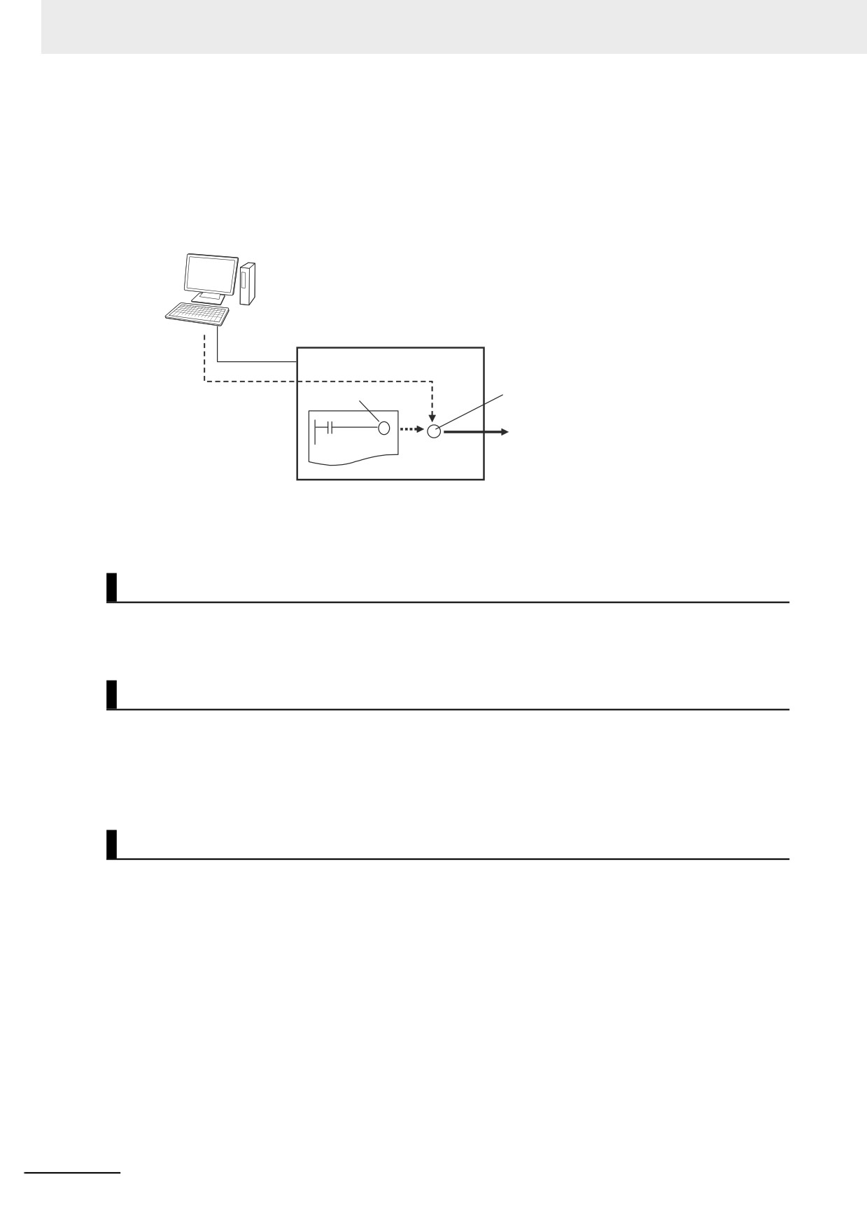
z Inputs
The I/O port and device variable change to the status that is specified with forced refreshing regard-
less of the status of the external input.
Sysmac Studio
8
Controller
I/O port
Device variable
(1) I/O port changed to
TRUE with forced
refreshing.
FALSE
TRUE
TRUE
(2) I/O port and device variable change to TRUE.
8-29
8 Controller Functions
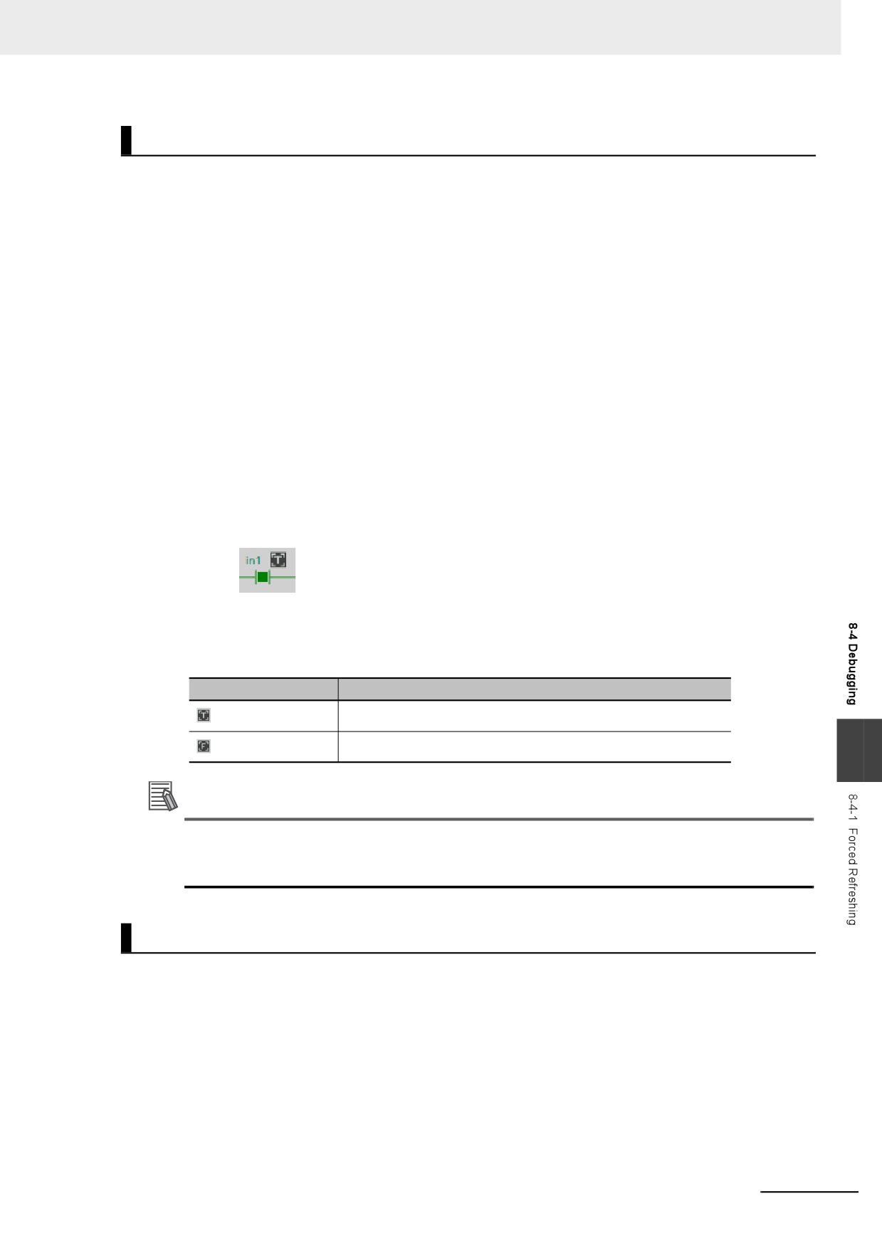
z Outputs
The I/O port and the output to the external device change to the status that is specified with forced
refreshing. In the user program, the status of the device variable that is assigned to the I/O port will
not necessarily be the status that was specified with forced refreshing. It will change with the results
of user program execution.
Sysmac Studio
Controller
I/O port
Device variable
(1) Output changed to
TRUE with forced
refreshing.
TRUE
FALSE
TRUE
(2) The I/O port and the output to the external
device change to TRUE. The device variable
changes with the result of user program
execution.
Applicable Areas
You can execute forced refreshing for the following I/O ports.
• I/O ports for EtherCAT slaves
Number of Simultaneous I/O for Forced Refreshing
The number of variables that you can refresh with forced refreshing is listed below.
• EtherCAT slaves: 64 points total
The number of external I/O points are given for the above limits. For example, if more than one variable
is assigned the same external I/O point as the AT specifications, it is counted as only one point.
Application
z Inputs
• To apply a simulated input signal to debug the user program
• To create a status that would occur only when a failure occurs (e.g., two exclusive bits turning ON or
OFF at the same time)
z Outputs
• To turn outputs ON and OFF to check wiring
• To intentionally turn OFF an output you do not want to operate regardless of results of user program
execution
8-30
8 Controller Functions
Operating Procedure
Operations can be performed from the following panes.
• Program Panes (Ladder diagram language)
• I/O Map
• Watch Tab Page
z Procedure for Forced Refreshing from Ladder Editor
1 Select Monitor from the Controller Menu. The monitor turns ON.
2 Double-click the ladder program, ladder function, or ladder function block under Programming
in the Multiview Explorer.
The rungs are displayed on the Ladder Editor in monitor status.
3 Right-click the input or output and select Forced Refreshing − TRUE. The input or output is
forced to TRUE. Right-click the input or output and select Forced Refreshing − FALSE. The
input or output is forced to FALSE.
4 The input or output in the Ladder Editor changes to TRUE or FALSE and the execution condi-
tion changes accordingly.
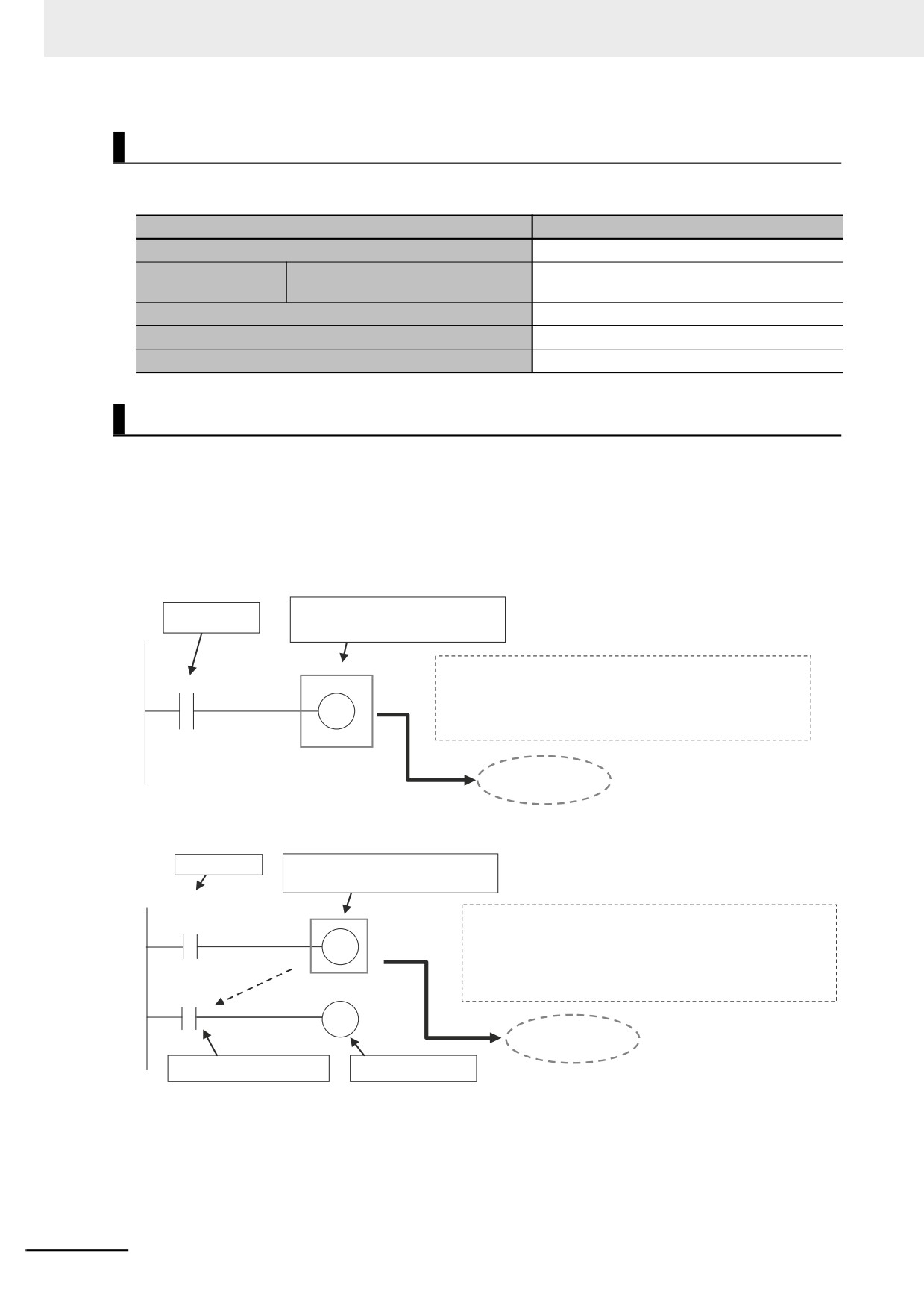
A mark that indicates that the input or output has forced status is displayed as shown below.
Ladder diagram
The TRUE or FALSE mark for forced status indicates the status that was specified for forced
refreshing. It does not indicate the current value of the input or output.
Forced status mark
Operation
TRUE specified with forced refreshing
FALSE specified with forced refreshing
8
Additional Information
If there are other variables that are assigned the same memory address as one that is specified
as the AT specification of a variable for which forced refreshing is specified, the forced status
mark is displayed for all of the variables with that AT specification.
Affect of Operating Modes and Power Interruptions
z Operating Modes for Forced Refreshing
You can execute forced refreshing in either PROGRAM mode or RUN mode. Forced refreshing is
not possible while there is a major fault level Controller error.
z Status of Forced Refreshing during Operating Mode Changes or Power
Interruptions
By default, the forced refreshing is cleared when the operating mode changes between RUN mode
and PROGRAM mode and when the power is interrupted.
8-31
8 Controller Functions
Holding/Clearing Forced Refreshing
Forced refreshing is retained and cleared according to changes in the status of the Controller as shown
below.
Change in status
Forced refreshing status
When power is turned ON
Cleared
When operating
RUN to PROGRAM mode
Cleared
mode changes
PROGRAM to RUN mode
After downloading
Cleared
When a major fault level Controller error occurs
Cleared
During online editing
Retained
Programming Precautions for Forced Refreshing
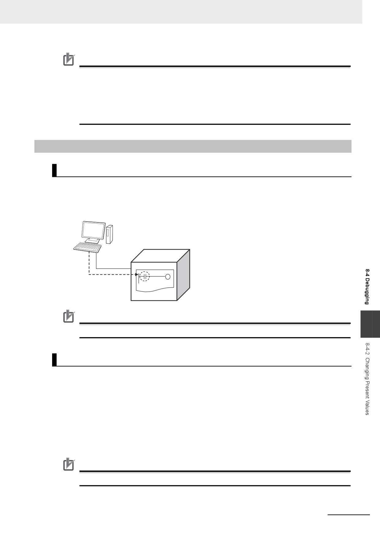
If forced refreshing is set in the user program, the status of variables for which forced refreshing is
specified are overwritten by the user program. Therefore, the status that is specified for forced refresh-
ing is not maintained in the user program. However, refreshing to external devices uses the values that
were specified for forced refreshing, and not the status of the variables in the user program. If forced
refreshing is used in a program, the values of variables in the program may be different from the status
of the external outputs.
Example: When a Is Refreshed to TRUE with Forced Refreshing
TRUE for forced refreshing, but
When FALSE
FALSE in the program.
a
• a is FALSE in the program.
x
• When the output is refreshed, information from forced
OFF
refreshing is reflected and the external output of a is
TRUE.
External output
of a: TRUE
When There Is Another Input that is Controlled by the Forced Input
When FALSE
TRUE for forced refreshing, but
FALSE in the program.
x
OFF
a
• a is FALSE in the program. Because of this, b is FALSE.
OFF
• When the output is refreshed, information from forced
refreshing is reflected and the external output of a is
a
TRUE.
OFF
b
OFF
External output
of a: TRUE
a is FALSE in the program.
As a result, b is FALSE.
8-32
8 Controller Functions
Precautions for Correct Use
• Confirm that no adverse effect will occur in the system before you use forced refreshing.
• Forced refreshing ignores the results of user program execution and refreshes I/O with the
specified values. If forced refreshing is used for inputs for which I/O refreshing is not sup-
ported, the inputs will first take the specified values, but they will then be overwritten by the
user program.
Depending on the difference in the forced status, the control system may operate unexpectedly.
8-4-2
Changing Present Values
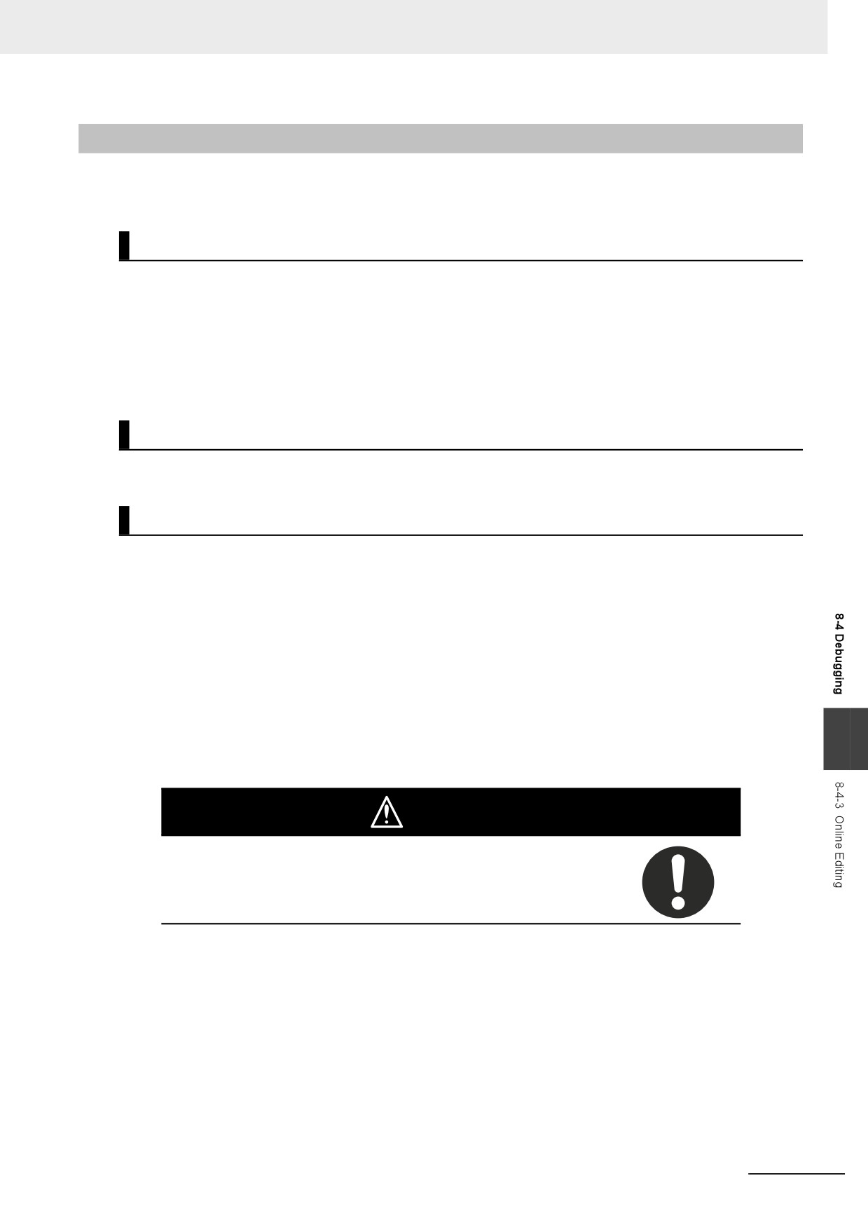
Description
You can change the present values of variables that are used in the user program and settings and you
can change program inputs and outputs to TRUE or FALSE. This allows you to check the operation of
the user program and settings.
Sysmac Studio
Controller
You can change the
values of variables
as required.
Precautions for Correct Use
8
Always confirm the safety of the system before you change the present value of a variable.
Application
z Changing Program Inputs and Outputs to TRUE or FALSE
You can change the value of any BOOL variable to TRUE or FALSE. The specified value is then
overwritten by the execution results of the user program. If the operating mode is changed or the
power supply is cycled, the initial value is restored. You can control BOOL variables in the Ladder
Editor, Watch Tab Page, or I/O Map.
z Changing the Values of Other Variables
You can change the present values of user-defined variables, system-defined variables, and device
variables as required. You can do this on a Watch Tab Page.
Precautions for Correct Use
Always confirm the safety of the system before you change the present value of a variable.
8-33
8 Controller Functions
Operating Procedure
Operations can be performed from the following panes to change the present values. Refer to the Sys-
mac Studio Version 1 Operation Manual (Cat. No. W504) for details on the operating procedures on the
panes.
• Program panes (ladder diagrams and ST)
• I/O Map
• Watch Tab Page
Precautions on Changing the Status of Outputs Assigned to
External Devices by Changing Present Values
Observe the following precautions when you change the status of an output that is assigned to an I/O
port of an EtherCAT output slave by changing a present value.
z Changing Present Values in the I/O Map in RUN Mode
Any value of an I/O port that is changed in the I/O Map is then overwritten by the execution results of
the user program. The value that was specified by changing the present value is not output to the
external device. To change the value of an I/O port and output that value to an external device, use
forced refreshing.
z Changing Present Values in a Watch Tab Page in PROGRAM Mode
The value that was specified in a Watch Tab Page by changing the present value of a device vari-
able* that is defined as an external or local variable is not output to the external device. To output a
specified value to an external device, do one of the following:
• Use forced refreshing.
• Change the present value in a Watch Tab Page of a device variable* that is defined as a global
variable.
* The devices variables must be assigned to an I/O port of an EtherCAT output slave.
8-34
8 Controller Functions
8-4-3
Online Editing
This section introduces online editing. Refer to the Sysmac Studio Version 1 Operation Manual (Cat.
No. W504) for details.
Introduction
The online editing function is used to add to or change part of a program in the Controller directly from
the Sysmac Studio.
You can select any of the following to perform online editing.
• POUs (programs, functions, and function blocks)
For a ladder diagram program, select a section.
• Global variables
Application
You can use online editing to change a user program without stopping the operation of the Controller.
Sysmac Studio Operations
z Performing Online Editing
1 Select the item to edit online.
2 Select Online Edit from the Project Menu.
3 Make the required changes.
4 Select Online Edit − Transfer from the Project Menu.
5 Check the results.
8
6 The user program will begin operation after online editing.
Caution
Execute online editing only after confirming that no adverse effects will occur
if the I/O timing is disrupted. If you perform online editing, the task execution
time may exceed the task period, I/O may not be refreshed with external
devices, input signals may not be read, and output timing may be changed.
8-35
8 Controller Functions
Precautions for Correct Use
• The differentiation status of differentiated instructions in a program that is edited online is ini-
tialized.
• When online editing changes are applied, the execution times of the tasks are extended. Set
the task period appropriately so that you do not cause a Task Period Exceeded error due to
online editing.
• If the power supply to the Controller is interrupted when online edits are being saved,* a major
fault level Controller error (User Program/Controller Configurations and Setup Transfer Error,
Incorrect User Program/Controller Configurations and Setup, or Non-volatile Memory
Restored or Formatted) occurs. If one of these errors occurs, download the user program
again.
• Do not execute the MC_SaveCamTable instruction while online edits are being saved.* Other-
wise the online edits may not be saved correctly.
* Online edits are saved from when you click the Yes Button in the confirmation dialog box until the dialog
box that indicates saving data to built-in non-volatile memory (which is displayed after the confirmation dia-
log box) closes.
8-36
8 Controller Functions
8-4-4
Data Tracing
You can use data tracing to sample variables without any additional programming. You can read and
check the data from the Sysmac Studio, and save the data to a file. This is used to start up, operate,
and maintain devices.
This section introduces data tracing. Refer to the Sysmac Studio Version 1 Operation Manual (Cat. No.
W504) for specific operating procedures.
Precautions for Correct Use
If you use data tracing to sample following variables, correct data may not be sampled.
• Structure members whose data size is 16 bits or more, except for system-defined variables for
motion control
• Array elements whose data size is 16 bits or more
If you sample the data with the above variables, perform either of the followings.
• Copy the above variables to the internal variables with a basic data type other than a data size
of 64 bits, and trace data for the copied variables.
• Use the settings for exclusive control of variables in tasks, and the task for which you use data
tracing to sample is set as a refreshing task.
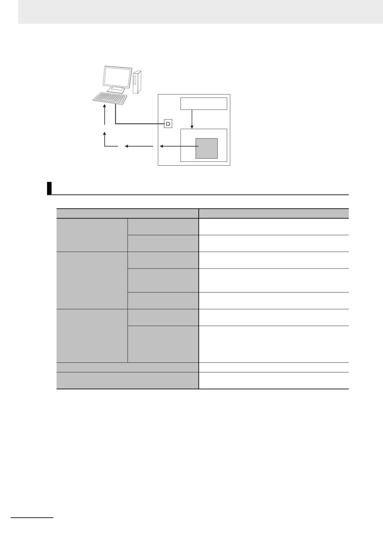
The two tracing methods are described below.
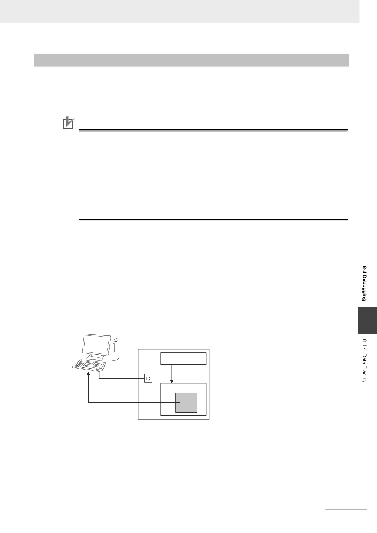
z
Triggered Tracing
Trigger conditions are set to record data before and after an event. Sampling stops automatically
when the maximum number of sampled variables is reached. Even if the Sysmac Studio is not
online, you can trace data when trigger conditions are met and then upload the data after placing the
Sysmac Studio online.
• You can check the flow of the program based on the status of changes in the present values of
variables.
• You can use the data to investigate the cause of unexpected changes in the values of variables.
8
Sysmac Studio
Controller
Data to trace
Sampling
Sampled data
Uploaded once.
When the maximum number of sampled
variables is reached, the trace stops
and the trace data is sent to the
Sysmac Studio and displayed.
z
Continuous Tracing
Sampling starts without any trigger and continues on even after 10,000 samples are collected. Sam-
ple data is transferred to the computer as it is collected and saved to a file. When the display buffer
is full, the data is automatically saved to a CSV file. You can use this to store trace results data for a
long tracing period in multiple CSV files.
8-37
8 Controller Functions
Sysmac Studio
Controller
Data to trace
Sampling
Sampled data
Continues.
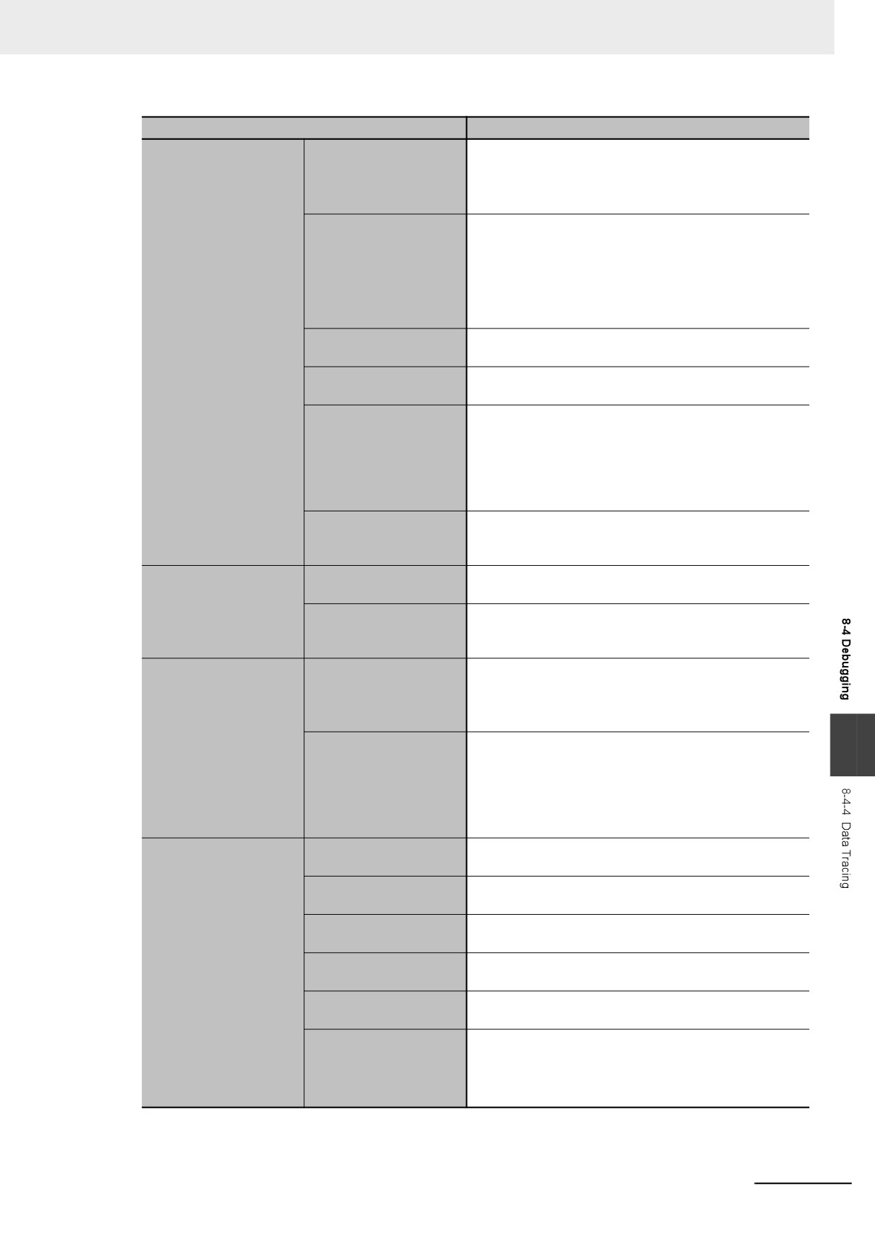
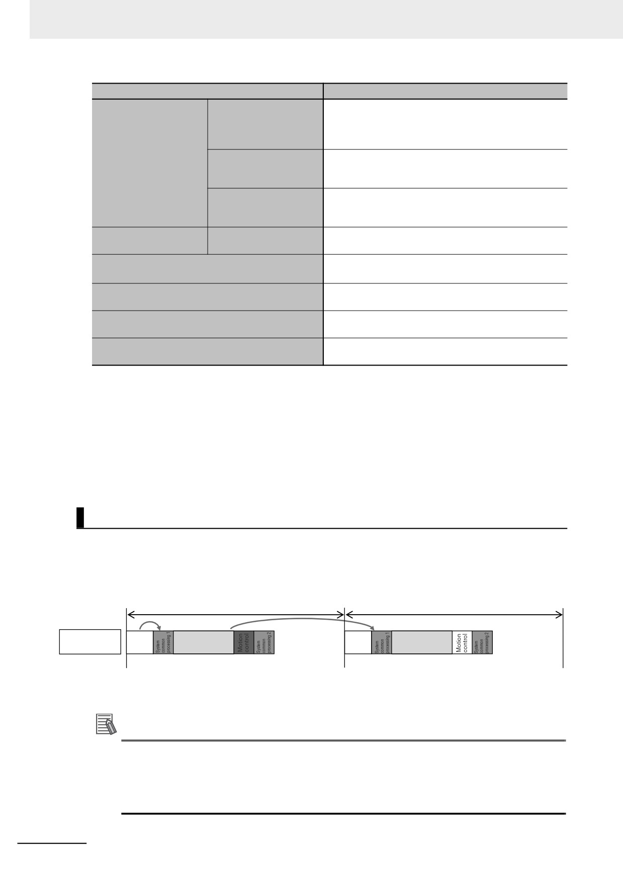
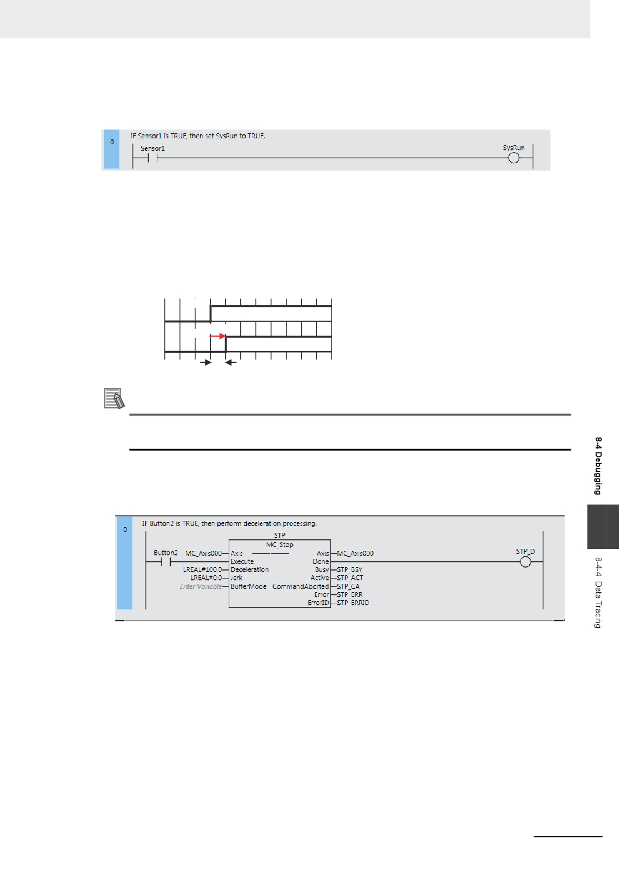
Data Tracing Specifications
The following table gives the specifications of data tracing.
Item
Description
Set a trigger condition to start sampling. Data from
Single triggered trace
before and after the condition is met is saved.
Types of data traces
Sample data is transferred to a computer as it is col-
Continuous tracing
lected and saved to a file.
Specify a task. The period of that task is set as the sam-
Period of specified task
pling period.
The time you enter is set as the sampling period. How-
Setting of timing of
Specified fixed interval
ever, the time you enter is rounded off to an integer mul-
sampling
tiple of the primary periodic task.
Trace sampling instruc-
With this method, sampling is performed whenever the
tion
TraceSamp instruction is executed in the user program.
Maximum number of
192 variables
targets
Basic data types except for text strings
Setting sampled data*1
Arrays (specify the element)
Data types
Enumerations
Members of structures and unions
Maximum number of records
10,000 samples per variable
The trigger position is set in respect to the overall trace
Setting trigger positions
time or quantity.
8-38
8 Controller Functions
Item
Description
Basic data types except for times, durations, dates, and
text strings
Condition data types
Arrays (specify the element), structures (specify the
member), and unions (specify the member)
Tracing is started when one of the following conditions is
met.
BOOL: TRUE or FALSE
Condition expression*2
Non-BOOL: Equals (=), Greater than (>), Greater than or
equal (≥), Less Than (<), Less than or equal (≤), Not
equal (≠)*3
Commands from Sys-
Tracing starts when the Trigger TRUE Button is clicked.
Setting triggers
mac Studio
Data Trace Trigger
Tracing starts when the TraceTrig instruction is exe-
instruction
cuted.
• If something other than the TraceSamp instruction is
used to set the timing of sampling, the trigger is evalu-
ated only once in the specified task period.
Evaluation timing
• If the TraceSamp instruction is used to set the timing
of sampling, the trigger is evaluated whenever the
instruction is executed.
A slider is used to set the percentage of sampling before
Delay
and after the trigger condition is met.
(Example: 20%/80%)
Commands from Sys-
Tracing is started when the Execute Button is clicked on
mac Studio
the Sysmac Studio.
Starting a trace
Tracing can be started when operation of the Controller
Starting tracing at start
starts (i.e., when the operating mode is changed from
of operation
PROGRAM mode to RUN mode).
• Tracing stops when the maximum value of 10,000
samples is reached.
Triggered traces
• Tracing is stopped when the Stop Button is clicked on
the Sysmac Studio.
Stopping a trace
• If stopping tracing is set as the operation to perform
8
when the maximum number of samples is reached,
tracing stops when the maximum number of samples
Continuous traces
or maximum amount of time is reached.
• Tracing is stopped when the Stop Button is clicked on
the Sysmac Studio.
Maximum data storage
You can set the maximum amount of time to save contin-
period
uous trace data.
Maximum data storage
You can set the maximum total size of all files saved
size
during continuous tracing.
You can set the number of samples to save in each file
Data items per file
during a continuous trace.
Setting continuous
You can specify the location to create files to save data
File save location
tracing
during a continuous trace.
You can specify a prefix to automatically add to the
File name prefix
beginning of the file names.
You can specify the operation to perform when the stor-
Setting of operation
age time period or size limit is reached.
when limit is reached
• Stopping the trace
• Deleting the oldest files and continuing
8-39
8 Controller Functions
Item
Description
You can display a graph where the X axis represents
time and the Y axis represents the value of the variable.
Graph display
You can display both BOOL variables and other vari-
ables on the same graph.
You can display the maximum value, minimum value,
Displaying trace results
Table display
average value, and value at the specified time for each
variable in a table.
You can position a virtual composition model in 3D space
3D Motion Monitor Dis-
and display the composition motion based on the com-
play Mode
mand positions and actual positions of the motion axes.
You can save the trace results and all settings other than
Exporting trace data
Exporting to CSV files
the trace number to a CSV file.
Number of data traces that can be executed
4 traces
simultaneously*4
You can display CSV format trace results on top of the
Importing trace data
current graph.
You can save the trace results in the project along with
Saving
the trace settings.
You can print graphs. The Sysmac Studio’s printing func-
Printing
tionality is used.
*1
You cannot perform data traces for the EN, ENO, P_off, P_on, P_CY, P_First_RunMode, P_First_Run and
P_PRGER system-defined variables, in-out variables that are used in function block instances, and variables
in functions.
*2
Data tracing will not start at the data trace starting point even if the trigger condition is met.
*3
Combinations of multiple condition expressions are not permitted. Also, the valid range for comparison con-
stants is determined by the valid range of the literal expressions for the variable type on the left side of the con-
dition expression.
*4
Trace numbers 0 to 3 are set for the NY-series Controllers. These numbers are used to execute instructions
and to access system-defined variables.
Data Trace Operation
Processing for data traces (sampling and trigger detection) are performed in System Common Process-
ing 1, between I/O refreshing and user program execution.
Example: If sampling is specified in the primary periodic task, data tracing is executed in System Com-
mon Processing 1, as shown in the following diagram.
Primary period
Primary period
Primary periodic
I/O
User program
I/O
User program
task
refreshing
execution
refreshing
execution
Display examples for data trace operations and execution results is given below for sampling in a spec-
ified task period.
Additional Information
I/O refreshing, user program execution, and motion control processing are all executed in the
same task period. For data tracing, user program execution and motion control processing for
the current task period and I/O refreshing for the next task period are displayed at the same time.
The timing charts in the NY-series Motion Control Instructions Reference Manual (Cat. No.
W561) are based on the task periods, so the display are not the same as those for data tracing.
8-40
8 Controller Functions
Example 1:
In this example, the SysRun variable is changed to TRUE in the user program when the Sensor1 vari-
able (assigned to the sensor input signal) changes to TRUE.
The data trace operations and display of the execution results are given below.
1. In data trace processing in System Common Processing 1, TRUE is obtained for Sensor1.
2. SysRun is changed to TRUE in the user program.
3. In data trace processing in System Common Processing 1 in the next primary period, TRUE is
obtained for SysRun.
Therefore, in the data trace display, SysRun is shown as TRUE one task period after Sensor1.
Data Trace Display
TRUE
Sensor1
Delayed.
TRUE
SysRun
1 task period
Additional Information
If the values of variables change during user program execution, the changes in the values and
changes for output processing for I/O refreshing are changed in the same task period.
Example 2:
When the Button2 variable (assigned to an input signal from a pushbutton) changes to TRUE during
velocity control, the user program in this example decelerates axis 0 (MC_Axis000) to a stop.
8
The data trace operations and display of the execution results are given below.
1. In data trace processing in System Common Processing 1, TRUE is obtained for Button2.
2. STP_BSY is changed to TRUE in the user program and the Motion Control Function Module per-
forms deceleration processing.
3. In data trace processing in System Common Processing 1 in the next primary period, TRUE is
obtained for STP_BSY and the status of the motion variable is obtained.
4. STP_ACT is changed to TRUE in the user program.
5. In data trace processing in System Common Processing 1 in the next primary period, TRUE is
obtained for STP_ACT.
8-41
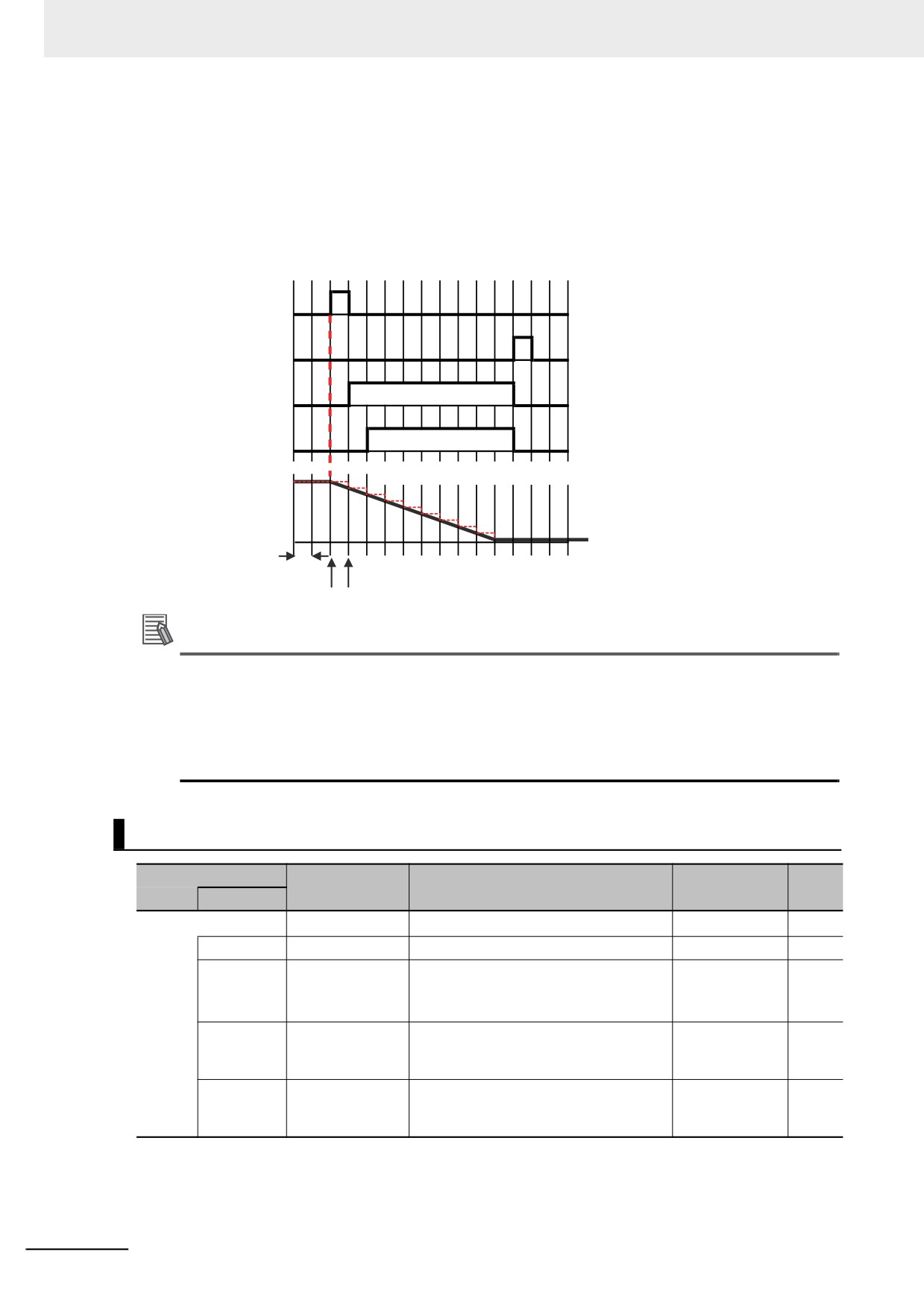
8 Controller Functions
The command value in the MC Function Module starts changing (B in the following diagram) when
STP_BSY changes to TRUE in the user program and the Motion Control Function Module starts to per-
form deceleration processing. The command value changes stepwise in synchronization with the pri-
mary periodic task. The data trace, however, interpolates the values to connect the values for the
previous and current periods. Therefore, the display shows that the command value for the Command
Velocity motion control variable (MC_Axis000.Cmd.Vel) changes one period early, i.e., when Button2
changes to TRUE (A in the following figure). The display also shows that STP_BSY changes to TRUE
one period after deceleration starts and then STP_ACT changes to TRUE after another period.
Button2
STP_D
STP_BSY
STP_ACT
Dotted lines: Command value in MC Function Module
MC_Axis000.Cmd.Vel
Task period
A B
Additional Information
For function blocks that contain motion control instructions, the values of input parameters are
passed to the input variables when execution of the function block starts, and the values of the
output variables are passed to the output parameters when execution of the function block ends.
(Refer to Variable Designations for Function Blocks on page 6-11.) On the data trace displays,
input parameters and input variable, and output parameters and output variables, change in the
same task period.
Related System-defined Variables
Variable name
Meaning
Description
Data type
R/W
Member
_PLC_TraceSta[0..3] *
_sTRACE_STA
R
.IsStart
Trace Busy Flag
TRUE when a trace starts.
BOOL
R
.IsComplete
Trace Completed
TRUE when a trace is completed.
BOOL
R
Flag
Changes to FALSE when the next trace
starts.
.IsTrigger
Trace Trigger
TRUE when the trigger condition is met.
BOOL
R
Monitor Flag
Changes to FALSE when the next trace
starts.
.ParamErr
Trace Parameter
Changes to TRUE when a trace starts if
BOOL
R
Error Flag
there is an error in the trace settings.
FALSE when the settings are normal.
* These numbers correspond to the data trace numbers 0 to 3.
Note You cannot use these system-defined variables in the user program. Use the GetTraceStatus instruction to
read the status of data tracing from the user program.
8-42
8 Controller Functions
8-4-5
Differential Monitoring
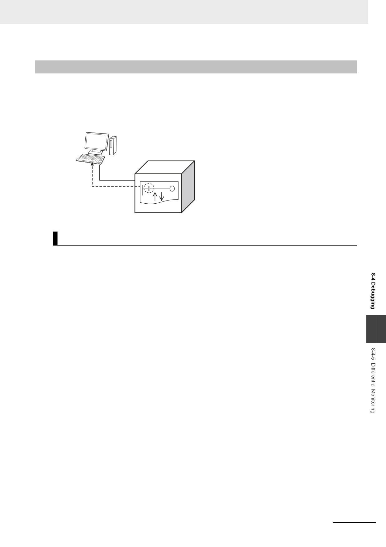
Differential monitoring reports the number of times the value of the specified BOOL variable matches
the specified condition. The specified condition is evaluated for a match in every task period of the pri-
mary periodic task (called the primary period). Differential monitoring provides a running total of the
number of times the condition is matched.
Sysmac Studio
Controller
The number of times the
value of the BOOL variable
changes is reported.
Application
You can use differential monitoring to check or count the number of times an external input signal turns
ON or OFF or a input in the user program changes to TRUE or FALSE. This is useful during system
commissioning and for troubleshooting operation failures during production.
8
8-43
8 Controller Functions
Specifications of Differential Monitoring
The specifications of differential monitoring are given in the following table.
Item
Specification
Differential monitoring
Number of variables
8 max.
condition
Specified variables
• BOOL
• Element of BOOL array
• BOOL member of structure or union
Condition expres-
• Change to TRUE
sion
• Change to FALSE
Conditional match
Timing
Once every primary period
evaluation
Match count
The number of times the specified variable matches the
condition is counted.
Starting and stopping
Start condition
Command from Sysmac Studio
Stop condition
• Command from Sysmac Studio
• Occurrence of a major fault level Controller error
• User program download
• Clear All Memory operation
• Disconnecting online connection to Sysmac Studio
Operating modes
• RUN mode
• PROGRAM mode
Differential Monitoring Conditions
The variables and the changes that you can monitor with differential monitoring are called differential
monitoring conditions. The specifications for the differential monitoring conditions are described below.
z Number of Variables
You can specify a maximum of eight variables. This means differential monitoring can detect the
numbers of times conditions are met for eight variables in parallel.
z Specified Variables
The data types of the variables that you can specify for differential monitoring are given below.
• BOOL
• Elements of BOOL arrays
• BOOL members of structures or unions
You cannot specify an array, structure, or union.
The types of variables that you can specify are listed below.
Type of variables
Specification
System-defined variables
Possible.*1
Semi-user-defined variables
Possible.
User-defined vari-
Global variables
Possible.
ables
Variables used in a program
Possible.
Variables used in a function block
Possible.*2
Variables used in a function
Not possible.
*1
The following variables cannot be used:
EN, ENO, P_Off, P_CY, P_First_RunMode, P_First_Run, and P_PRGER.
*2
In-out variables cannot be used.
8-44
8 Controller Functions
z Condition Expressions
The condition of the change in the variable to detect is called the condition expression. There are
two types of condition expressions that you can select from. You specify a condition expression for
each variable.
• Change to TRUE
• Change to FALSE
Precautions for Correct Use
For example, we will assume the condition expression was set to a change to TRUE. Even if the
value of the specified variable is TRUE when differential monitoring is started, the status of the
value of the variable is not detected as a change to TRUE. The value of the variable must first
change to FALSE and then to TRUE to be considered as a change to TRUE.
When Conditions Are Evaluated and the Match Count
The condition for the specified variable is evaluated every primary period. The value of the variable
from the previous evaluation is compared with the value of the variable for the current evaluation. If
the value of the variable that matches the specified condition has changed, the count is incre-
mented.
• The number of times a condition match occurs is counted separately for each variable.
• The count values are reset to zero when differential monitoring is started.
• The count value for just one variable cannot be reset to zero.
Precautions for Correct Use
• Even if the value changes to match the condition expression more than one time within the
same primary period, the count will be incremented only once in each primary period.
• If the values of the variable are the same at the time of the previous and current evaluations,
the condition is not considered to be a match, even if the value changed between evaluations.
8
8-45
8 Controller Functions
Start Condition and Stop Condition
Use the Sysmac Studio to start differential monitoring.
Normally, use the Sysmac Studio to stop differential monitoring. Differential monitoring will stop
automatically at the following times.
• When a major fault level Controller error occurs
• When the user program is downloaded
• When the Clear All Memory operation is performed
• When an online connection to the Sysmac Studio is broken
Procedure
Use the following procedures to control differential monitoring. Refer to the Sysmac Studio Version 1
Operation Manual (Cat. No. W504) for details.
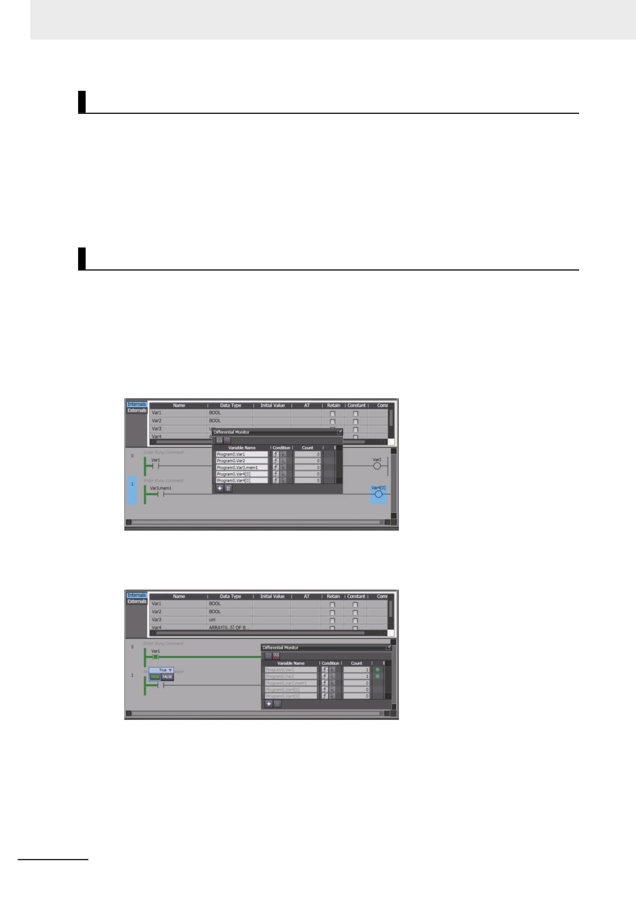
1 Select Differential Monitor from the View Menu on the Sysmac Studio.
2 Right-click a variable that can be specified for differential monitoring and select Add Differen-
tial Monitor.
3 Set the differential monitoring condition expression for each variable in the Differential Monitor
Window.
4 Execute the user program.
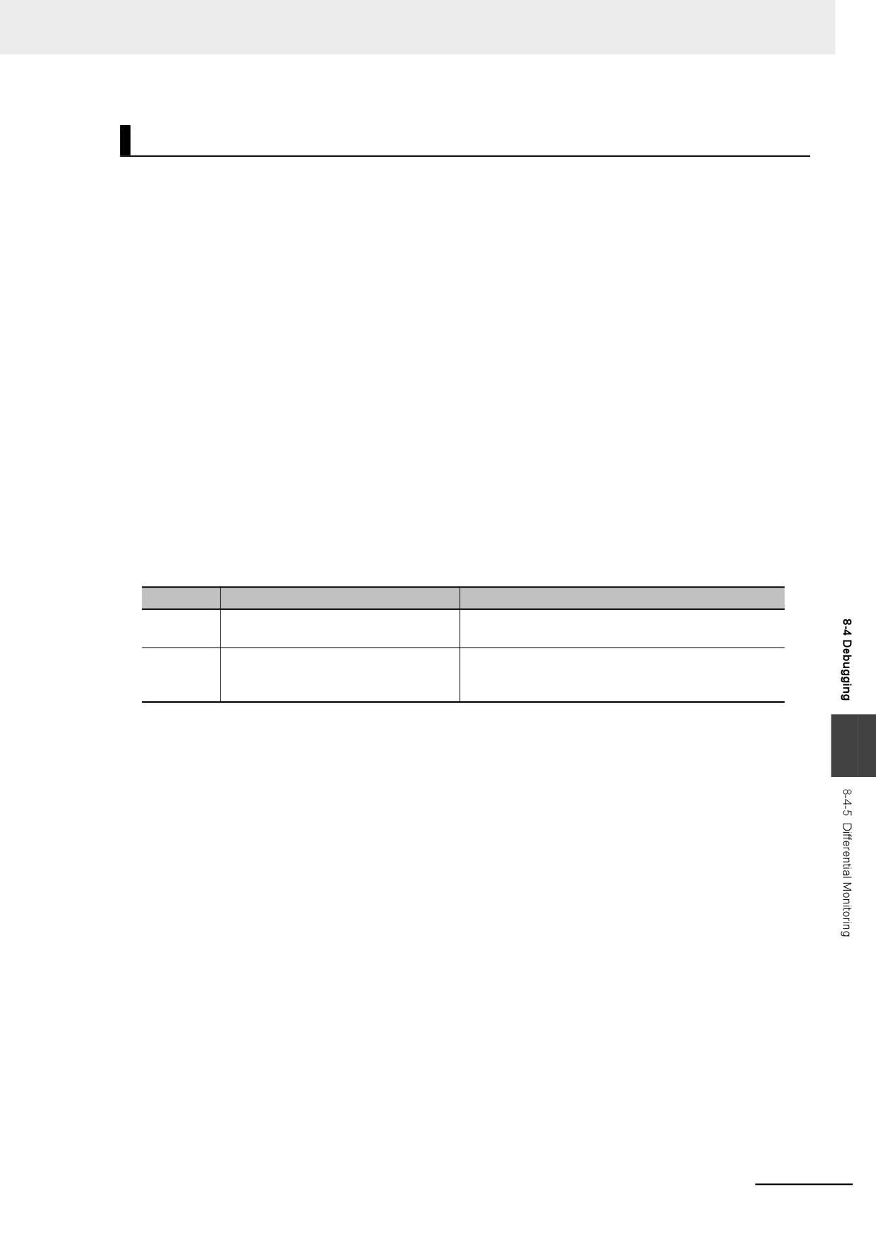
The number of times that the condition is met for each variable is displayed in the Differential
Monitor Window.
8-46
8 Controller Functions
Precautions for Differential Monitoring
Observe the following precautions when you use differential monitoring.
z Loss of Communications with Sysmac Studio While Differential Monitoring Is
in Progress
Let’s assume that communications with the Sysmac Studio were cut off during differential monitoring
because the communications cable was disconnected or because the Sysmac Studio ended due to
an error. In such cases, the Controller will continue execution of differential monitoring. To restart
execution of differential monitoring, you must resume communications with the Sysmac Studio and
stop differential monitoring.
z Simultaneous Execution of Differential Monitoring
You cannot run differential monitoring from more than one copy of the Sysmac Studio running on the
same computer or from the Sysmac Studio running on different computers.
z Specifying Global Variables and External Variables
You can specify global variables or external variables (which specify global variables in POUs) for
differential monitoring. Keep in mind that the values of global variables and external variables are
updated at different times. A global variable is updated as soon as the value is written. An external
variable, however, is updated only when the Controller executes the POU in which that external vari-
able is declared. The following figure shows this. In this example, the following two variables are
monitored.
Variable
Type of variable
POU that executes the read/write
GVar1
Global variable
The P1 program that is assigned to the primary peri-
odic task
P2.GVar1
This is an external variable that is
The P2 program that is assigned to the periodic task
declared in the P2 program and points
to GVar1.
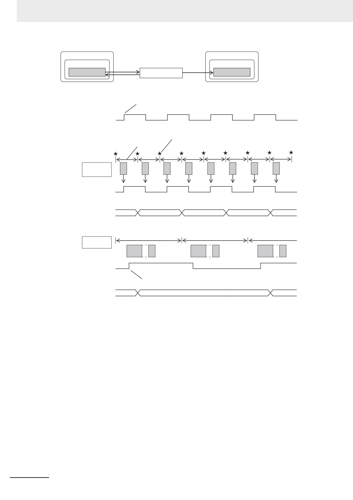
The GVar1 global variable is read and written by the P1 program that is assigned to the primary peri-
odic task. Therefore, it will be updated in the primary period as long as the program writes to it every
8
period. The P2.GVar1 external variable, however, is updated only when the Controller executes the
P2 program that is assigned to the periodic task. This means the external variable is updated only in
the task period of the periodic task. Because the task period of the periodic task is longer than the
primary period, the count for P2.GVar1 is updated fewer times than the count for GVar1.
8-47
8 Controller Functions
Refreshing task
Accessing task
Program P1
Program P2
Read/write
Reading
External variable GVar1
Global variable GVar1
External variable GVar1
The GVar1 global variable is updated as soon as P1 writes a value to the
P1.GVar1 external variable.
TRUE
GVar 1
FALSE
(global
variable)
Timing for condition evaluation by differential monitoring
Primary period
Primary periodic task
P1
P1
P1
P1
P1
P1
P1
P1
(refreshing task)
TRUE is
FALSE is
TRUE is
FALSE is
TRUE is
FALSE is
TRUE is
FALSE is
written.
written.
written.
written.
written.
written.
written.
written.
P1.GVar1 TRUE
(external
FALSE
variable)
Number of times
0
1
2
3
4
condition for GVar1 is
met (change to TRUE)
Task period
Periodic task
(accessing task)
P2
P2
P2
TRUE
P2.GVar1
FALSE
(external
variable)
The value of the P2.GVar1 external variable is updated only when
P2 is executed.
Number of times
0
1
2
condition for P2.GVar1 is
met (change to TRUE)
8-48
8 Controller Functions
8-5
Event Logs
This section describes the event logs.
8-5-1
Introduction
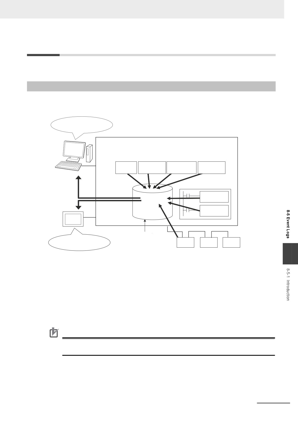
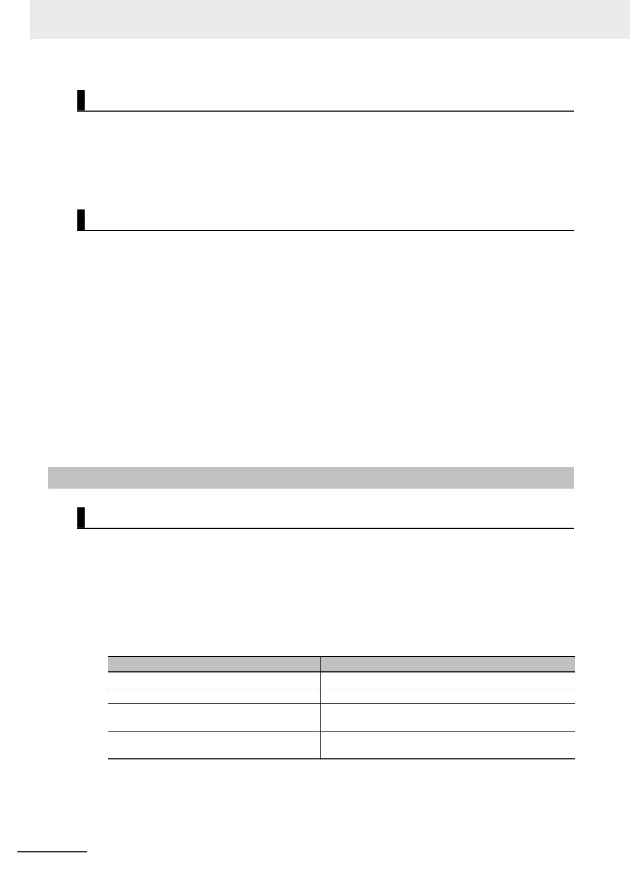
The event logs contain records of events,* such as errors, status changes, and user-defined events,
that occurred in the NY-series Controller.
You can check the current
Controller events and the event
log of past events.
NY-series Controller
Event
PLC Function
Motion Control
EtherCAT Master
EtherNet/IP
sources
Module
Function Module
Function Module
Function Module
Sysmac Studio
Or
User program
Create User-defined
Error (SetAlarm)
Event logs
instruction
NS/NA-series PT
Create User-defined
Information (SetInfo)
instruction
Backed up with a
You can check the current
non-volatile memory
EtherCAT
Controller events and the event
slave
log of past events.
8
* Here, events are unscheduled events that occur on the Controller, such as errors. “Event” refers to an error or to
information that does not indicate an error but for which the user must be notified by the Controller or for a user
definition. There are two types and four classifications of events.
• Controller events
Controller errors
Controller information
• User-defined events
User-defined errors
User-defined Information
To use an NS/NA-series PT to check events, connect the PT to the built-in EtherNet/IP port on the Con-
troller.
Precautions for Correct Use
• Refer to the NY-series Troubleshooting Manual (Cat. No. W564) for details on the PT's Trou-
bleshooter.
8-49
8 Controller Functions
Features
Event logs have the following features.
• In addition to error records, various records are recorded for events such as the time the power sup-
ply is turned ON or OFF, and the time when operation is started.
• You can check these records based on the time. You can therefore use them to isolate the causes of
errors when problems occur.
Types of Events
Events are classified as shown below.
z System-defined Events (Controller Events)
The Controller automatically detects these events. Controller events include events for the function
modules in the NY-series Controller and EtherCAT slaves. The different types of system-defined
events are as follows:
• Controller errors
• Controller information
z User-defined Events
These are events that occur in applications that the user developed. You can execute instructions to
create the following types of events.
• User-defined errors
• User-defined information
You can read the event logs from the Sysmac Studio or from an HMI.
8-5-2
Detailed Information on Event Logs
Event Sources
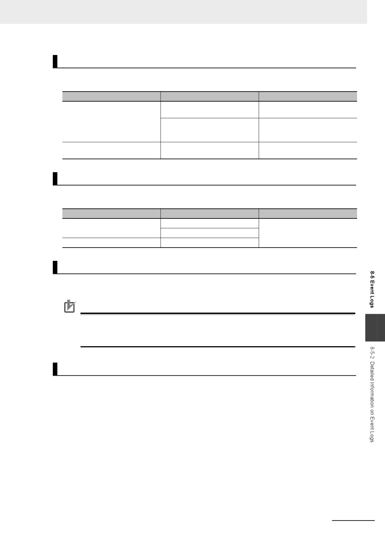
This information identifies where an event occurred in the Controller. The event sources are given
below for Controller events and user-defined events.
z Sources of Controller Events
Controller events occur in the function modules in the Controller.
For some function modules, there is more detailed information about the event source. This informa-
tion is called the detailed event source.
The following are Controller events.
Event source
Source details
PLC Function Module
Instructions or Windows
Motion Control Function Module
Common, axis, or axes group
EtherCAT Master Function Module
Communications port, EtherCAT master, EtherCAT Cou-
pler Unit, NX Unit, or EtherCAT slave
EtherNet/IP Function Module
Communications port, communications port 1, internal port
1, CIP, FTP, NTP, or SNMP
z Sources of User-defined Events
User-defined events occur in the PLC Function Module.
8-50
8 Controller Functions
Category
This information displays the category of event log. It is used to access error logs from the Sysmac Stu-
dio or an HMI.
Event type
Event log category
Description
Controller events
System log
The Controller automatically detects
and records these events.
Access log
This is a record of events that have
affect Controller operation due to
user actions.
User-defined events
User event log
This is a log of events that are
defined by the user.
Number of Records
Each event log can contain the following number of records. If the number of events exceeds the num-
ber of records permitted, the Controller overwrites the oldest events.
Event type
Event log category
Maximum number of records
Controller events
System log
2,048 events
Access log
User-defined events
User event log
Retaining Events during Power Interruptions
The NY-series Controller uses a non-volatile memory to retain the event logs when the power is inter-
rupted.
Precautions for Correct Use
The event logs are retained with a non-volatile memory. They are not retained when a UPS is not
connected to the Industrial PC or when the Industrial PC was not normally shut down.
8
Periodically export event logs as required.
Event Codes
Event codes are assigned to Controller events by the system in advance according to the type of event.
Event codes are assigned to user-defined events by the user. Controller event codes are 8-digit hexa-
decimal values. You can use the Get Error Status instruction to read the error codes of current errors.
You can assign a decimal number from 1 to 60,000 as the event code for a user-defined event.
8-51
8 Controller Functions
Event Levels
Each event has an event level that indicates its level. The event level depends on the type of event.
Levels are defined separately for Controller events and user-defined events.
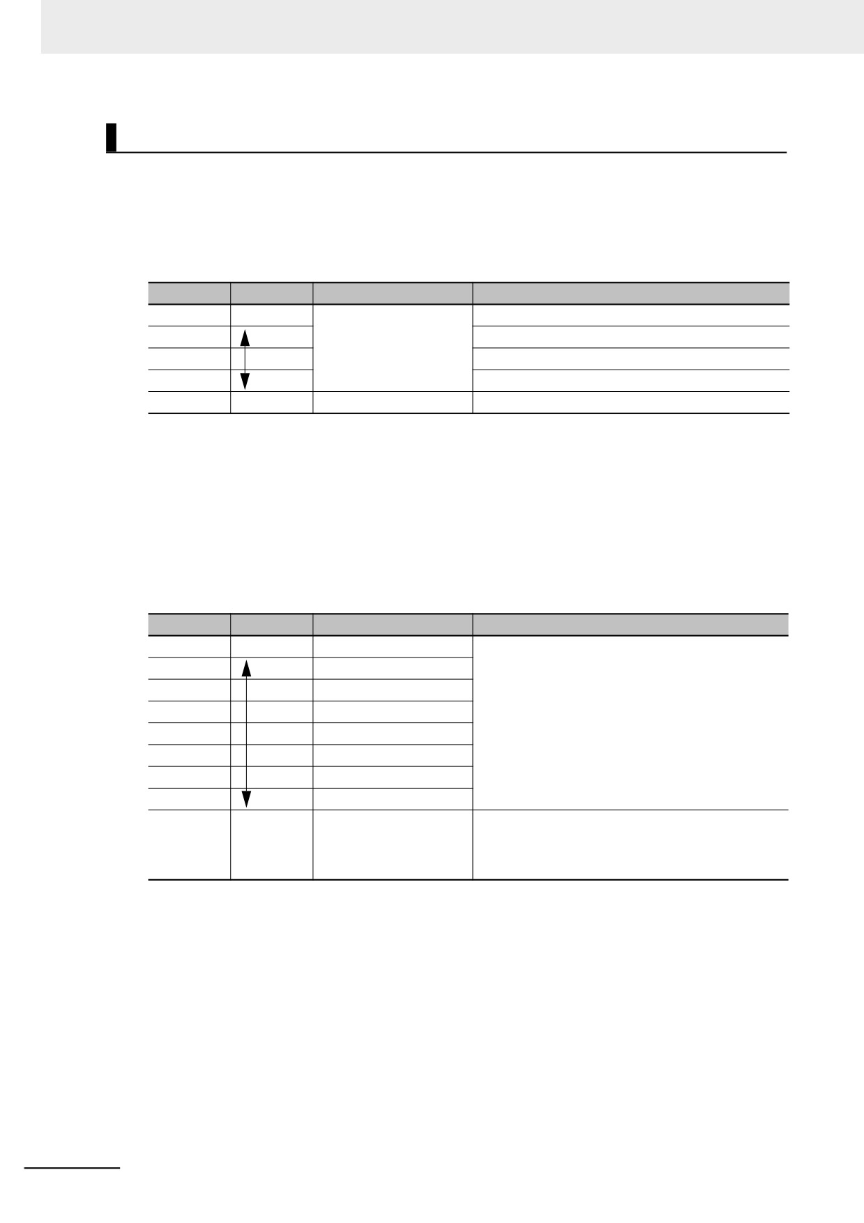
z
Controller Events
Controller events are classified into five levels according to the degree of the effect that the events
have on control, as shown in the following table.
No.
Level
Classification
1
High
Controller errors
Major fault level
2
Partial fault level
3
Minor fault level
4
Observation level
5
Low
Controller information
Information level
Errors with a higher level have a greater impact on the functions that the Controller provides, and
are more difficult to recover from.
When an event in one of these levels occurs, the Sysmac Studio or an HMI will display the error.
z
User-defined Events
User-defined events are classified into the following levels. These levels are defined by the NY-
series System.
The event levels are defined for user-defined events.
No.
Level
Type
Meaning
1
High
User fault Level 1
These event levels indicate a user-defined error in
an application. The user executes the SetAlarm
2
User fault Level 2
(Create User-defined Error) instruction to create the
3
User fault Level 3
event.
4
User fault Level 4
5
User fault Level 5
6
User fault Level 6
7
User fault Level 7
8
User fault Level 8
9
Low
User Information
These event levels indicate user-defined information
in an application. The user executes the SetInfo
(Create User-defined Information) instruction to cre-
ate the event.
8-52
8 Controller Functions
Displaying Event Logs
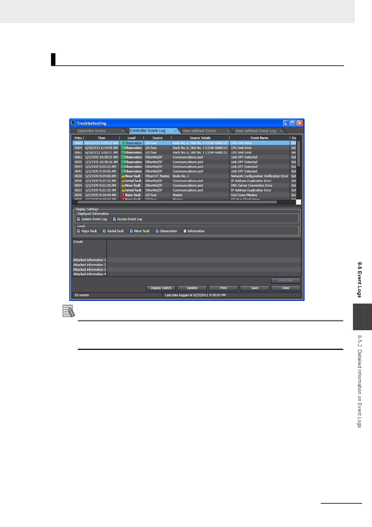
The Sysmac Studio or an HMI displays two event logs: the Controller event log and the user-defined
event log. The Controller logs include both the access log and the system log.
The Sysmac Studio can also display the error logs that are recorded in the EtherCAT slaves.
The events in these logs are displayed in tables on the Sysmac Studio. Select an event from the table
to display detailed information.
Additional Information
8
If an event occurs in the Controller that is not supported by the version of the Sysmac Studio or
an HMI, the source is displayed as “Unknown” and the event name is displayed as “Unknown
Event.” The event code and attached information are displayed correctly.
8-53