Omron IPC Machine Controller Industrial Panel PC / Industrial Box PC. Software User’s Manual (Industrial PC Platform NY-series) - page 15
9 Backup Functions
9-3
Disabling Backups to SD Memory
Cards
You can disable the backup function from writing data to the Virtual SD Memory Card to protect your
programming assets.
The following two functions are applicable for disabling backup to the Virtual SD Memory Card.
• Backups using system-defined variables
• Backups from the SD Memory Card Window on the Sysmac Studio
Backup function using the BackupToMemoryCard instruction is not applicable. This means that you can
backup data using the BackupToMemoryCard instruction even if the Prohibit data backup to the SD
Memory Card setting is set to be used.
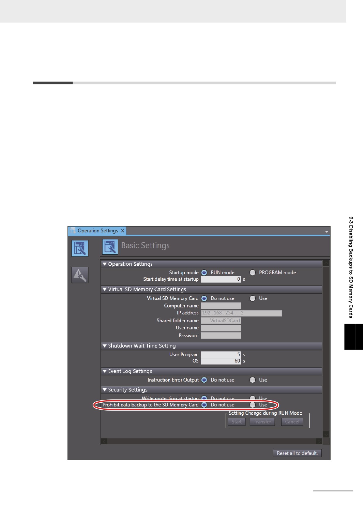
Use the following procedure to set the Prohibit data backup to the SD Memory Card setting.
Select the Use Option for the Prohibit data backup to the SD Memory Card setting in the Basic
Settings Display of the Operation Settings Tab Page under Configurations and Setup - Controller
Setup on the Sysmac Studio.
9
9 - 19
9 Backup Functions
9-4
Sysmac Studio Controller Backups
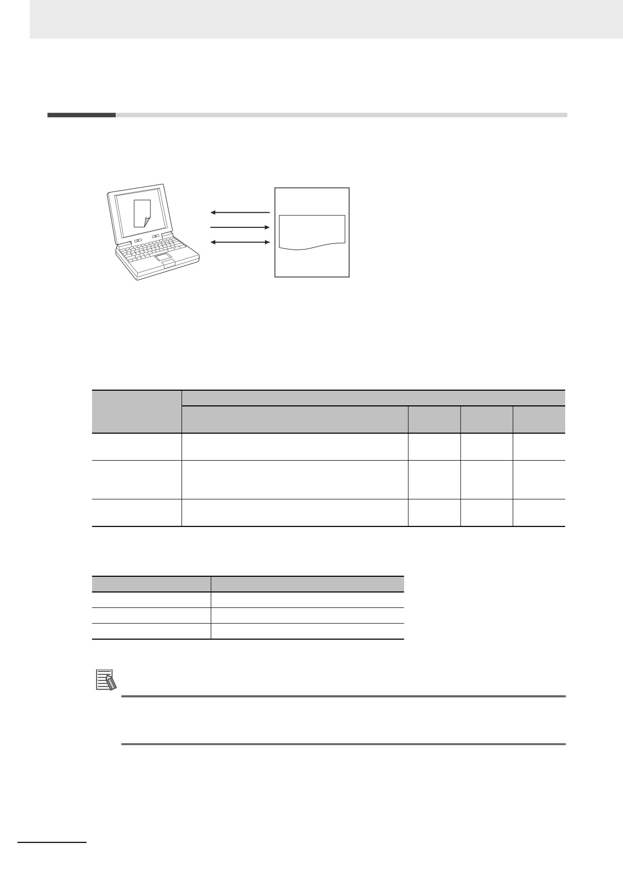
You can use Sysmac Studio to back up, restore, and verify Controller data from a computer.
Sysmac Studio
Controller
Backing up data
Restoring data
Data that is
Verifying data
backed up
Backup file
Restore command file
Automatic transfer command file
Verification results files
When you back up data, the backup file, restore command file, and automatic transfer command file
are created in the specified directory in the computer. The functions of the backup-related files are
given in the following table.
Function
File
Backing
Restor-
Verifying
Contents
up data
ing data
data
Backup file
This file contains the Controller data that is handled
Created.
Accessed.
Accessed.
by the functions that are related to data backup.
Restore command
This file specifies the data groups to transfer when
Created.
Accessed.
Accessed.
file
restoring data. You can edit this file with a text editor
on a computer to specify the data groups to transfer.
Automatic transfer
This file is not used in an NY-series Controller.
Created.
Nothing is
Nothing is
command file
done.
done.
You can execute these functions in the following operating modes.
Processing
Applicable operating modes
Backing up data
RUN mode and PROGRAM mode
Restoring data
PROGRAM mode
Verifying data
RUN mode and PROGRAM mode
Additional Information
You can change the operating mode of the Controller while a backup or verification operation is
in progress. However, an error will occur if the backup or verification cannot be processed nor-
mally due to faulty memory in the Controller, or some other failure.
9-20
9 Backup Functions
9-4-1
Backup (Controller to Computer)
The Controller data is saved in the specified directory on the computer.
Processing Contents
• For the Units and slaves settings in the backup data, you must select all EtherCAT slaves that are
connected.
• The backing up conditions for data groups are given in the following table.
Data group
Restoring condition
User program and settings
The CPU Unit must be selected.
IP address of built-in EtherNet/IP port*1
The CPU Unit must be selected.
Present values of variables
The CPU Unit must be selected.
Event logs
The CPU Unit must be selected.
Units and slaves settings
The EtherCAT slaves must be selected.
Absolute encoder home offsets
The CPU Unit must be selected.
*1. A Controller with unit version 1.14 or later and Sysmac Studio version 1.18 or higher are required.
• When you back up data, the backup file, restore command file, and automatic transfer command file
are created in the specified directory in the computer.
• If the backup-related files are already in the specified directory, they are overwritten.
• If an error occurs while writing the backup-related files to specified directory, the previous backup-
related files will be deleted. Also, the new backup-related files will not be created.
• If an error occurs before the new backup-related files are created, the previous files are retained and
the new files are not created.
• The value of the _BackupBusy (Backup Function Busy Flag) system-defined variable will be TRUE
during the backup operation.
Procedure
1 Select Backup − Backup Controller from the Tools Menu on the Sysmac Studio.
9
2 Specify the folder in which to save the backup file, restore command file, and automatic transfer
command file.
3 Click the Execute Button on the Backup Confirmation Dialog Box.
The data is backed up and the backup file, restore command file, and automatic transfer com-
mand file are created.
9-21
9 Backup Functions
9-4-2
Restore (Computer to Controller)
The data in a backup file in the specified directory on the computer is restored to the Controller.
This operation can only be performed in PROGRAM mode.
Processing Contents
• The data in a backup file in the specified directory on the computer is restored to the Controller.
• You can select the data groups to restore from the Sysmac Studio. The conditions for restoring the
data are given in the following table.
Data group
Restoring condition
User program and settings
The CPU Unit must be selected.
IP address of built-in EtherNet/IP port*1
The IP address of built-in EtherNet/IP port must be selected.
Present values of variables
The present values of variables that are specified for retention
with the Retain attribute must be selected.
Units and slaves settings
The EtherCAT slaves must be selected.
Absolute encoder home offsets
The absolute encoder home offsets must be selected.
*1. A Controller with unit version 1.14 or later and Sysmac Studio version 1.18 or higher are required.
• If an error occurs in the checks that are performed before starting to restore the data, the previous
data will be retained in the Controller.
• If the power supply to the Controller is interrupted while the data is being restored, a User Pro-
gram/Controller Configurations and Setup Transfer Error (a major fault level Controller error) will
occur. If that occurs, the data in the Controller is not dependable. Use one of the following methods to
clear the error.
• Perform the restore operation again.
• Clear all of memory and then download the project from the Sysmac Studio.
• If the present values of variables that are set to be retained (with the Retain attribute) are not set to
be restored, the previous present values of those variables will be retained. However, the values of
any variables that do not meet the retain conditions are initialized. These are the retain conditions for
the variable:
• The variable name, data type name, and data type size must be the same before and after restor-
ing the data.
• Cycle the power supply to all of the EtherCAT slaves after you restore data.
Procedure
1 Select Backup − Restore Controller from the Tools Menu on the Sysmac Studio.
2 Specify the folder that contains the backup file and restore command file.
3 Click the Execute Button on the Restoration Confirmation Dialog Box.
The restoration operation is executed.
9-22
9 Backup Functions
9-4-3
Verify (between Controller and Computer)
The Controller data and the data in a backup file in the specified directory on the computer are com-
pared.
Processing Contents
• The Controller data and the data in a backup file in the specified directory on the computer are com-
pared. You can select the data groups to verify from the Sysmac Studio. The conditions for verifying
the data are given in the following table. If you specify all data, all of the following data will be com-
pared.
Data group
Verification condition
User program and settings
The CPU Unit must be selected.
IP address of built-in EtherNet/IP port*1
The IP address of built-in EtherNet/IP port must be selected.
Units and slaves settings
The EtherCAT slaves must be selected.
*1. A Controller with unit version 1.14 or later and Sysmac Studio version 1.18 or higher are required.
• The results of the verification are displayed in the dialog box on the Sysmac Studio.
• The value of the _BackupBusy (Backup Function Busy Flag) system-defined variable will be TRUE
during the backup operation.
Procedure
1 Select Backup − Compare with Backup File from the Tools Menu on the Sysmac Studio.
2 Specify the folder that contains the backup file.
3 Click the Execute Button on the Comparison Confirmation Dialog Box.
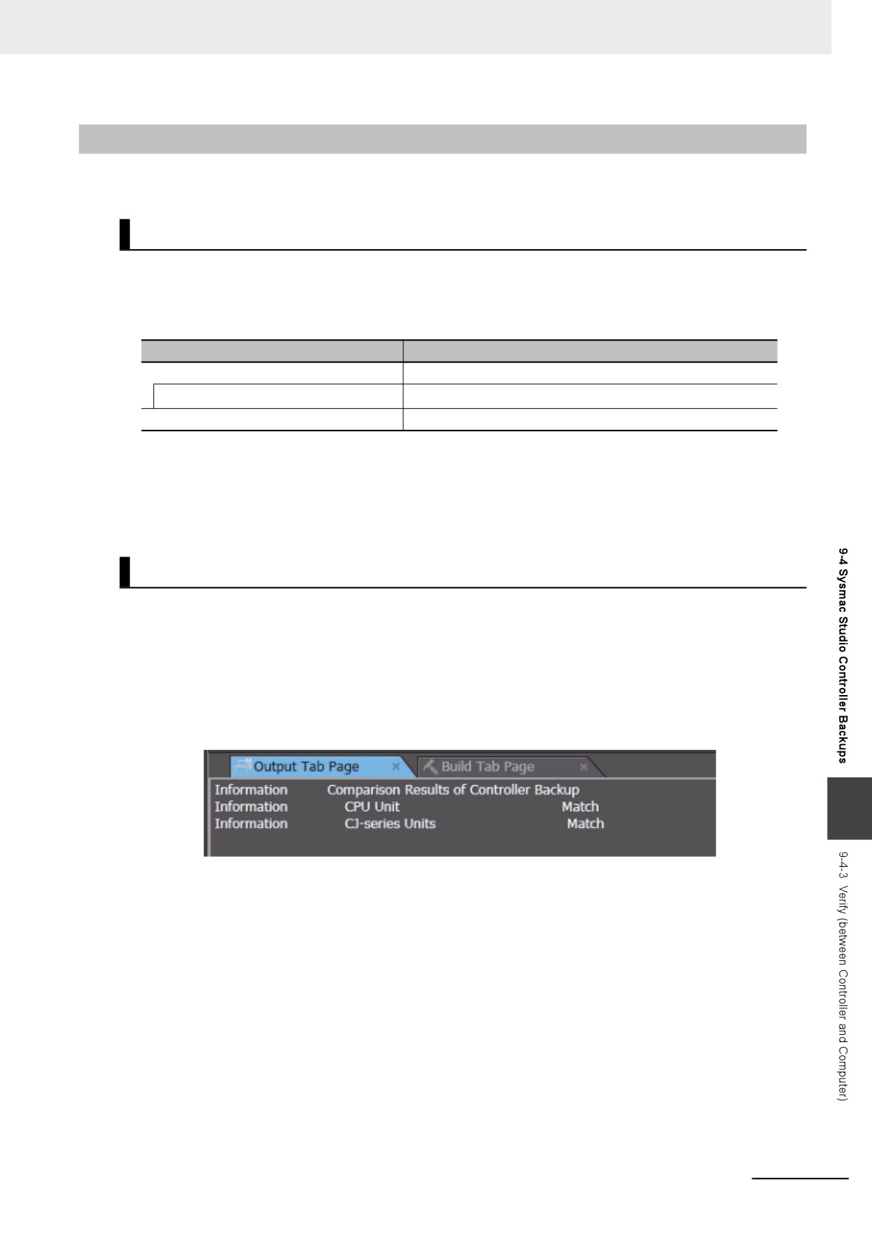
The data is compared and the verification results files are created in the folder that contains the
backup file. The comparison results are also displayed in the Output Tab Page.
9
9-23
9 Backup Functions
9-5
Importing and Exporting Sysmac
Studio Backup File Data
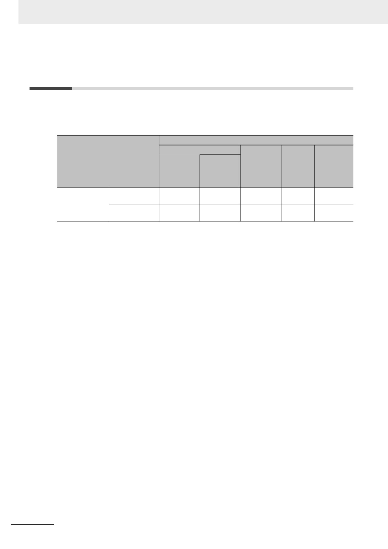
You can create or read from a backup file in the specified directory on the computer from the Sysmac
Studio project without using the Controller.
This following data is processed:
Data group
User program and settings
Absolute
IP address
Present val-
Units and
Function
encoder
of built-in
ues of vari-
slaves
home off-
EtherNet/IP
ables
settings
sets
port*1
Importing and
Exporting
OK*2
OK
NA
NA
NA
exporting Sysmac
backup file data
Studio backup file
Importing
OK*3
OK
NA
OK
NA
data
backup file data
*1. With a combination of the Controller with unit version 1.14 or later and Sysmac Studio version 1.18 or higher, IP
address of the Built-in EtherNet/IP Port Settings can be used as a data group. IP address is included in the user
program and settings other than the above combination.
*2. The following data is not processed:
Controller names: the built-in EtherNet/IP port name
Controller Setup: the tag data link settings for the built-in EtherNet/IP port
The operation authority verification
Data Trace Settings
*3. The following data is not processed:
• Controller names: the built-in EtherNet/IP port name
• The operation authority verification
• Data Trace Settings
Refer to the Sysmac Studio Version 1 Operation Manual (Cat. No. W504) for more information on these
functions.
9-24
9 Backup Functions
9-6
Sysmac Studio Variable and Memory
Backup Functions
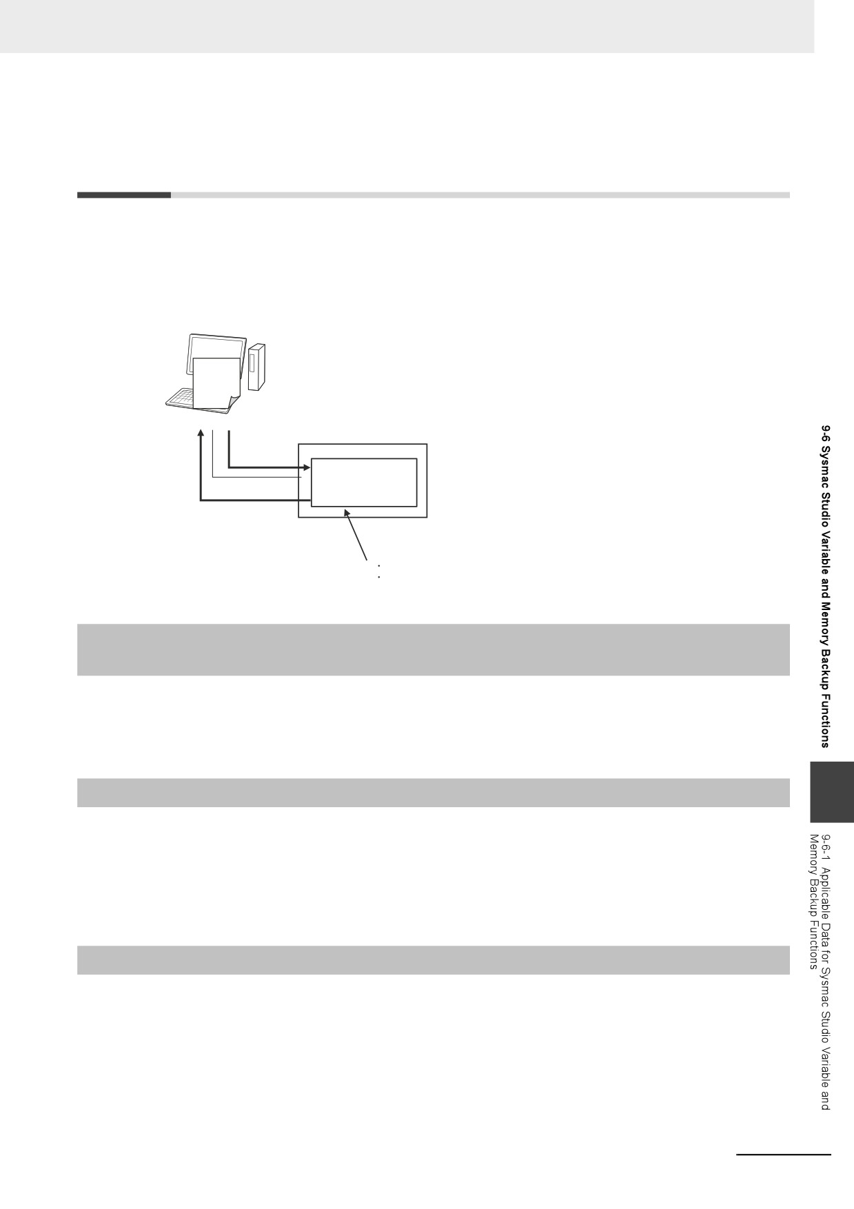
You can back up the present values of the non-volatile memory in the Controller to an XML file on your
computer or restore the non-volatile memory from a previously saved backup file.
This section describes the applicable data, operating procedures, and Controller model compatibility for
the Sysmac Studio variable and memory backup functions.
Sysmac Studio
Select Backup − Backup Variables and
Memory or Backup − Restore Variables and
XML file
Memory from the Tools Menu.
NY-series Controller
Restoring
Present values of
non-volatile memory
Backup
Backup and Restore Targets:
Present values of retained variables
Absolute encoder home offsets
9-6-1
Applicable Data for Sysmac Studio Variable and Memory Backup
Functions
The applicable data for Sysmac Studio variable and memory backup functions are given below.
• Present values of variables with a Retain attribute
• Absolute encoder home offsets
9-6-2
Using Sysmac Studio Variable and Memory Backup Functions
9
The Sysmac Studio procedure is as follows:
Place the Sysmac Studio online with the Controller, and select either Backup − Backup Variables and
Memory or Backup − Restore Variables and Memory from the Tools Menu.
Refer to the Sysmac Studio Version 1 Operation Manual (Cat. No. W504) for details.
9-6-3
Compatibility between NY-series Controller Models
With the Sysmac Studio variable and memory backup functions, you can restore the data even if the
models of the NY-series Controller for backing up and restoring data are different.
9-25
9 Backup Functions
9-7
Backup Functions When EtherCAT
Slaves Are Connected
For EtherCAT slaves, you can use the SD Memory Card backup functions, the Sysmac Studio
Controller backup functions, and Sysmac Studio backup import function.
This section provides precautions for connected EtherCAT slaves for the data that is backed up,
backup support according to Controller status, restore conditions, and specific models of EtherCAT
slaves.
Additional Information
To use the backup functions for EtherCAT Slave Terminals, refer to 9-8 Backup Functions When
EtherCAT Slave Terminals Are Connected.
9-7-1
Backed Up EtherCAT Slave Data
The data that is backed up for EtherCAT slaves is given in the following table.
Setting
Data that is backed up
EtherCAT Master Settings
The following data is backed up: Model name, Product name, Number of Slaves,
PDO Communications Cycle, Fail-soft Operation Setting, Wait Time for Slave
Startup, PDO communications timeout detection count, Revision Check Method,
and Serial Number Check Method.
EtherCAT Slave Settings
The following data is backed up: Device name, model name, product name, revi-
sion, node address, enabled/disabled settings, serial number, PDO map settings,
enable distributed clock, reference clock, and initial parameter setting function.
9-26
9 Backup Functions
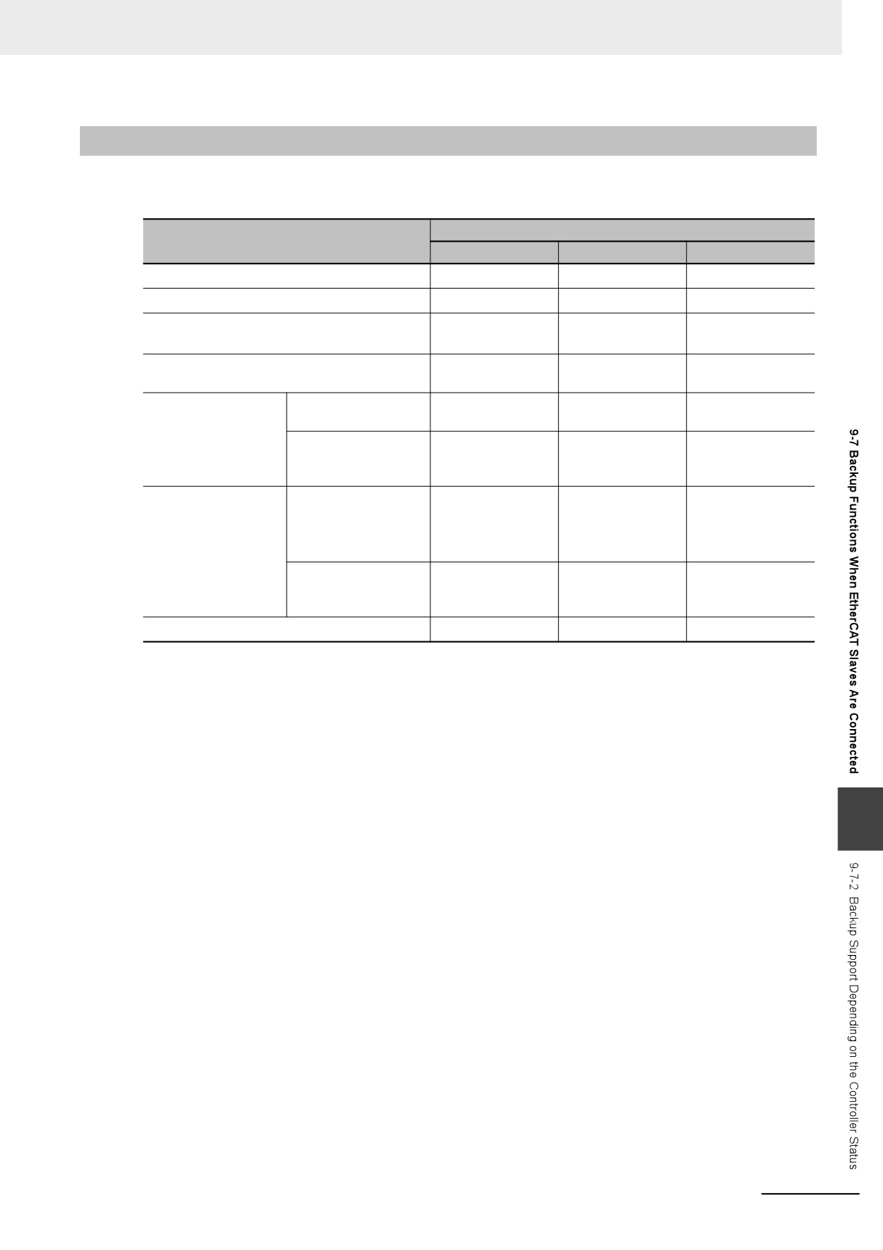
9-7-2
Backup Support Depending on the Controller Status
The following table shows when backup, restore, and verify operations can be performed for EtherCAT
slaves based on the Controller status.
Execution
Controller status
Backing up data
Restoring data
Verifying data
Link OFF
Not possible.*1
Not possible.*2
Possible.*3
Illegal master status*4
Not possible.*1
Not possible. *2
Possible*3
Network configuration mismatch with configu-
Not possible.*1
Not possible.*2
Possible*3
ration information*5
Network configuration mismatch with configu-
Possible.
Not possible.*2
Possible*3
ration at time of backup
Disabled slave in net-
Disabled slaves in
Possible.
Possible.
Possible.
work configuration
actual configuration
No disconnected
Possible.
Possible.
Possible.
slaves in actual con-
figuration
Slave disconnected
Disconnected slaves
Not possible.*1
Possible.
Possible.
for “Disconnect” des-
in actual configuration
Data for discon-
Data for discon-
ignation in network
nected slaves is
nected slaves is
configuration
also restored.
also verified.
No disconnected
Not possible.*1
Not possible.*2
Possible*3
slaves in actual con-
figuration
Slave Initialization Error
Not possible.*1
Not possible.*2
Possible*3
*1. An EtherCAT Slave Backup Failed event is recorded in the event log.
*2. An EtherCAT Slave Restore Operation Failed event is recorded in the event log.
*3. The verification results will show differences.
*4. This refers to the following errors: Duplicate Slave Node Address, Network Configuration Information Error, Net-
work Configuration Error, Slave Initialization Error, Network Configuration Verification Error for Fail-soft Opera-
tion Setting of “Stop”, and Link OFF Error.
*5. This refers to the following errors: Network configuration mismatch with configuration when the backup was per-
formed (incorrect connection ports for slaves on branched networks are treated as a mismatch) and network
configuration information mismatch with actual network configuration (incorrect connection ports for slaves on
branched network are treated as a match).
9
9-27
9 Backup Functions
9-7-3
Conditions for Restoring EtherCAT Slave Data
The following conditions must be met before you can restore the backup data to the EtherCAT slaves.
• The backup files must contain the EtherCAT slave data.
• The Network Configuration Information must match the actual network configuration where data is
being restored.
• The revision values that are preset in the EtherCAT slaves must match. The conditions used to eval-
uate the match are based on the Revision Check Method in the backup file. Even if you set the Revi-
sion Check Method to not check revisions, the restoration operation cannot be performed if the set
revision is greater than the actual revision of the slave. You cannot change the revision values.
• The serial numbers must match if the Serial Number Verification setting in the backup file is set to
verify the serial numbers.
• The node addresses must match if the hardware switches are used to set the node address.
Precautions for Correct Use
• Cycle the power supply to all of the EtherCAT slaves after you restore data.
• All slaves are disconnected after the data is restored. You must connect the target slaves
again to reset the disconnected slaves.
• If you set the Serial Number Verification setting in the backup file to verify the serial numbers,
the data cannot be restored if you replace any of the hardware for the EtherCAT slaves. In this
case, change the network configuration in Sysmac Studio and download the configuration data
to the new slaves. Then, transfer the slave parameters to restore the slaves to their original
condition. If the node address is set on the hardware switches, use the same setting as when
the data was backed up.
9-28
9 Backup Functions
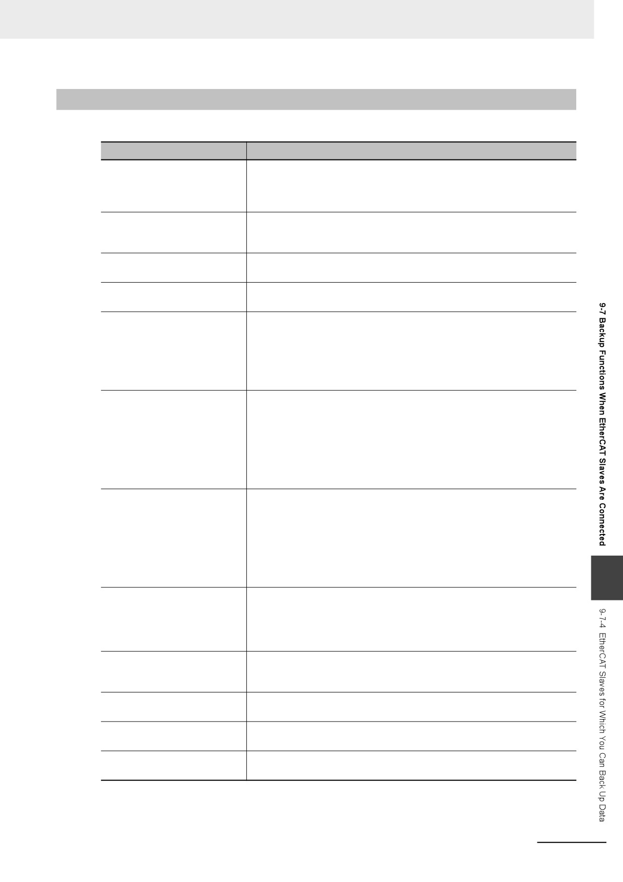
9-7-4
EtherCAT Slaves for Which You Can Back Up Data
You can back up data for the following EtherCAT slaves. Observe the precautions.
EtherCAT slaves
Precautions
NX-ECC NX-series EtherCAT
You cannot back up, restore, or compare data for Safety Control Units on Eth-
Coupler Unit
erCAT Slave Terminals. Refer to the NX-series Safety Control Unit User's
Manual (Cat. No. Z930) for information on importing and exporting settings
for a Safety Control Unit.
R88D-1SN-ECT and
*1
R88D-1SAN-ECT AC
Servo Drives
R88D-KN-ECT AC Rotary
*1*2
Servo Drives
R88D-KN-ECT-L AC Lin-
*1*2
ear Servo Drives
3G3AX-MX2-ECT and 3G3AX-
The parameters in the Inverter are not restored. Refer to Procedure to Write
RX-ECT Inverters
Parameters for an 3G3AX-MX2-ECT or 3G3AX-RX-ECT Inverter on page 9-
30 to write the parameters from the Sysmac Studio to the Inverter.
If you execute verification without writing the parameters, the verification
result for the inverter will be Not matched in the EtherCAT slaves verification
result file.
FH-3 and FH-1
The setup data for these Vision Sensors (such as the scene data and system
Vision Sensors
data) is not backed up, restored, or verified.
To transfer the setup data to an external file or to the Vision Sensor, select
Sensor data − Save to file or Sensor data − Load from file from the Tools
Menu on the editing tab page for the Configurations and Setup of the Sysmac
Studio.
Refer to the Vision System FH/FZ5 series User’s Manual (Cat. No. Z340) for
details.
FQ-M-ECT and FQ-
The setup data for these Vision Sensors (such as the scene data and system
M-M-ECT Vision Sen-
data) is not backed up, restored, or verified.
sors
To transfer the setup data to an external file or to the Vision Sensor, select
Sensor data − Save to file or Sensor data − Load from file from the Tools
Menu on the editing tab page for the Configurations and Setup of the Sysmac
Studio.
For details, refer to the FQ-M-series Specialized Vision Sensor for Positioning
User’s Manual (Cat. No. Z314).
9
FZM1--ECT Vision Sen-
The setup data for these Vision Sensors (such as the scene data and system
sors
data) is not backed up, restored, or verified.
To save the setup data for the Vision Sensor to a USB memory device or to
write it to the Controller, use the software tool for the Vision Sensor. Refer to
the FZ3 Vision Sensor User’s Manual (Cat. No. Z290) for details.
GX-D16, GX-D328,
*1
and GX-OC1601 Digital I/O Ter-
minals
GX-AD0471 and GX-DA0271
*1
Analog I/O Terminals
GX-EC0211 and GX-EC0241
---
Encoder Input Terminals
GX-JC0 EtherCAT Junction
There is no internal data that needs to be backed up.
Slaves
9-29
9 Backup Functions
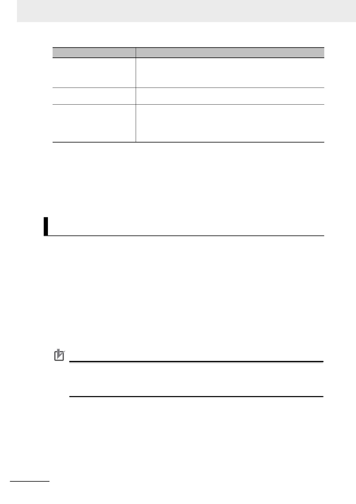
EtherCAT slaves
Precautions
ZW-CE1T Confocal Fiber Type
None of the settings are backed up, restored, or verified.
Displacement Sensors
Refer to the Displacement Sensor ZW Series Confocal Fiber Type Displace-
ment Sensor User’s Manual (Cat. No. Z332) for information on saving the set-
tings and loading them to the Controller.
E3NW-ECTE3X-ECT Digital
The parameters in the Sensor are not backed up, restored, or verified.
Sensors
Slaves from other manufacturers
• Data is backed up, restored, and verified only when it is correctly defined in
the ESI. To back up, restore, or verify data that is not defined in the ESI, use
the software tool for the slave.
• If backing up, restoring, or verifying data fails, contact the manufacturer of
the slave for the appropriate procedures.
*1. Cycle the power supply to a slave after you restore data. Cycle the power supply to a slave before you verify the
data after you restore it. The verification will fail if you do not cycle the power supply before you perform the ver-
ification.
*2. If any of the following conditions applies, do not turn the Servo ON while the data is being backed up or restored
before you verify the data. If you turn the Servo ON while the data is being backed up or restored before you
verify the data, the parameters are updated before the verification operation and may cause differences in the
verification results.
• When the Realtime Autotuning Mode Selection (3002 hex) is set to 1 to 4, or 6 (enabled).
• When the Adaptive Filter Selection (3200 hex) is set to 1 or 2 (enabled).
Procedure to Write Parameters for an 3G3AX-MX2-ECT or 3G3AX-RX-ECT
Inverter
The parameters in the Inverter are not restored.
Use the follow procedure from the Sysmac Studio to write the backup parameters to the Inverter. Refer
to the Sysmac Studio Version 1 Operation Manual (Cat. No. W504) for details.
1 Import the Inverter parameters from the backup file with the backup file import function of the
Sysmac Studio.
The Inverter parameters are displayed on the Inverter Parameters Tab Page for the Controller
Configurations and Setup of the Sysmac Studio.
2 Confirm that the model number of the Inverter in the parameters that you imported agrees with
the model number of the Inverter that is actually connected.
3 Download the parameters to the Inverter using the “To Drive” menu on the Inverter Parameters
Tab Page for the Controller Configurations and Setup of the Sysmac Studio.
Precautions for Correct Use
If you use the Inverter Mode Selection parameter (parameter number b171) in a 3G3AX-MX2-
ECT Inverter, change the Inverter to the mode that was used when the backup data was created
before you write the parameters. After you change the mode setting, you must initialize the
Inverter to enable the change.
9-30
9 Backup Functions
9-8
Backup Functions When EtherCAT
Slave Terminals Are Connected
For EtherCAT Slave Terminals, you can use the SD Memory Card backup functions, the Sysmac Studio
Controller backup functions, and Sysmac Studio backup import function.
This section provides information on the data that is backed up, backup support according to Controller
status, and restore conditions when EtherCAT Slave Terminals are connected.
Precautions for Correct Use
You cannot back up, restore, or compare data for Safety Control Units on EtherCAT Slave Termi-
nals. Refer to the NX-series Safety Control Units User’s Manual (Cat. No. Z930) for information
on importing and exporting settings for a Safety Control Unit.
9-8-1
Backing Up Data in an EtherCAT Slave Terminal
The data that can be backed up for an EtherCAT Slave Terminal is different for the EtherCAT Coupler
Unit and the NX Units. The data that is backed up is given in the following table.
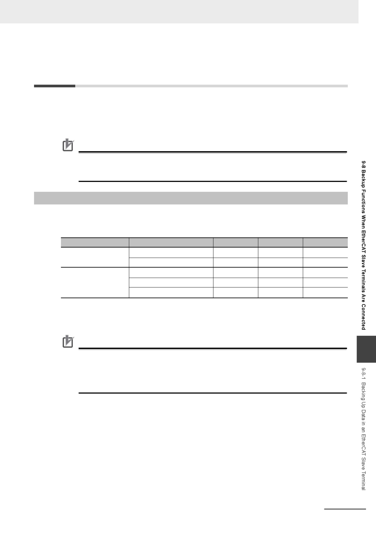
(OK: Applicable, NA: Not applicable)
Unit
Data
Backing up data
Restoring data
Verifying data
EtherCAT Coupler Unit
Configuration information*1
OK
OK
OK
Unit operation settings
OK
OK
OK
NX Units
Configuration information*1
OK
OK
OK
Unit operation settings
OK
OK
OK
Unit application data*2
OK
OK
OK
*1. The configuration information includes the Unit configuration information and I/O allocation information.
*2. This is the specific data for each NX Unit. Some NX Units do not have Unit application data.
Precautions for Correct Use
9
To restore backup data to an EtherCAT Slave Terminal that has an identical Unit configuration to
the EtherCAT Slave Terminal from which data was backed up, make sure that all hardware
switches are set to the same settings as when the backup was made. Backup data cannot be
restored if the hardware switches are set differently from those in the backup data. This will
cause a Restore Operation Failed to Start (EtherCAT Slave) observation event to occur.
9-31
9 Backup Functions
9-8-2
Backup Support Depending on the EtherCAT Slave Terminal
Status
The following table shows when backup, restore, and compare operations can be performed for
EtherCAT Slave Terminals based on the EtherCAT Slave Terminal status.
Execution
EtherCAT Slave Terminal status
Backing up data
Restoring data
Verifying data
Automatic creation of the Unit configuration information
Possible.*1
Possible.*2
Possible.
Waiting for NX Unit participation
Not possible.*3
Not possible.*4
Possible.*5
Watchdog time error in EtherCAT Coupler Unit or NX
Not possible.*3
Not possible.*4
Possible*5
Unit
During Bus Controller Error
Not possible.*3
Not possible.*4
Possible*5
During Unit Configuration Information Error
Not possible.*3
Possible.
Possible*5
During Unit Configuration Verification Error
Not possible.*3
Possible.
Possible*5
The Unit Configuration does not agree with the Unit
---
Not possible.*4
Possible*5
Configuration information in the backup data.
*1. The backup contains information saying that the Unit configuration information does not exist.
*2. After the data is restored, automatic Unit configuration status continues.
*3. A Backup Failed event is recorded in the event log.
*4. A Restore Operation Failed event is recorded in the event log.
*5. The verification results will show differences.
9-8-3
Conditions for Restoring EtherCAT Slave Terminal Data
The following conditions must be met before you restore the backup data to the EtherCAT Slave Termi-
nals.
• The backup files must contain the data for the EtherCAT Coupler Unit and NX Unit.
• The original Unit Configuration in the backup must match the actual Unit configuration where data is
being restored.
• The serial number of the EtherCAT Coupler Unit from which the data was backed up and the serial
number of the EtherCAT Coupler Unit to which the data is restored must be the same. However, this
assumes that the setting of the Serial Number Check Method in the Unit operation settings of the
Communications Coupler Unit in the backup file is set to Setting = Actual device.
• The serial numbers of the NX Units from which the data was backed up and the serial numbers of the
NX Units to which the data is restored must be the same. However, this assumes that the setting of
the Serial Number Check Method in the Unit operation settings of the Communications Coupler Unit
in the backup file is set to Setting = Actual device.
• The hardware switch settings of the EtherCAT Coupler Unit from which the data was backed and the
hardware switch settings of the EtherCAT Coupler Unit to which the data is restored must be the
same.
• The unit version setting of the EtherCAT Coupler Unit from which the data was backed up and the
unit version of the actual EtherCAT Coupler Unit to which the data is restored must be the same.
• The unit version settings of the NX Unit from which the data was backed up and the unit versions of
the actual NX Units to which the data is restored must be the same.
9-32
9 Backup Functions
9-9
Backup-related Files
This section describes the specifications of the backup-related files. These backup-related files apply to
all backup functions except for the Sysmac Studio variable and memory backup functions.
9-9-1
Types of Backup-related Files
There are four types of files that are related to backup functions: backup files, restore command files,
automatic transfer command files, and verification results files.
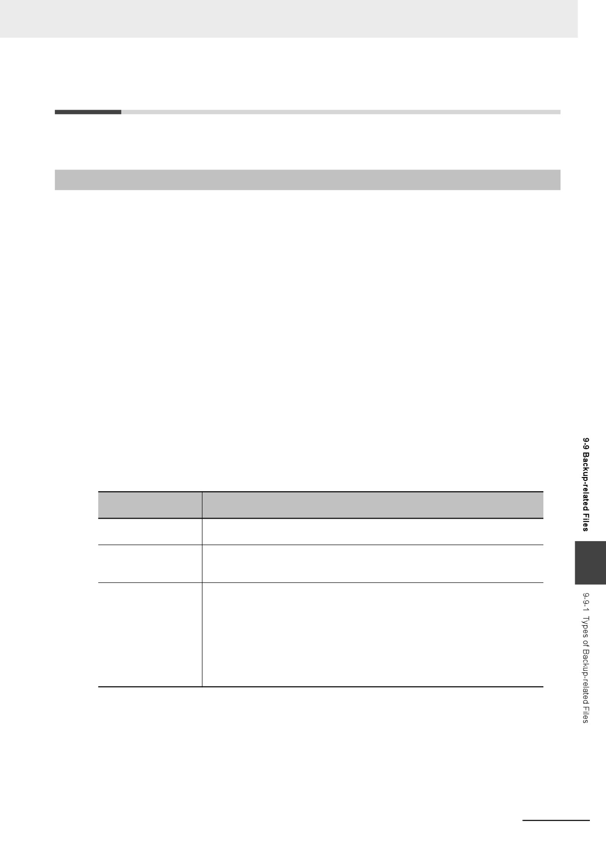
z Backup File
This file contains the Controller data that is handled by the backup-related functions. These files are
created when data is backed up.
z Restore Command File
This file specifies the data groups to transfer by restoring data from a Virtual SD Memory Card. You
can edit this file with a text editor on a computer to specify the data groups to transfer. These files
are created when data is backed up.
z Automatic Transfer Command File
This file is not used in an NY-series Controller.
z Verification Results Files
The verification results files contain the results of comparing the Controller data and the data in a
backup file on the Virtual SD Memory Card.
There are three different verification results files, as described below. These files are created when
you perform a verification using the SD Memory Card backup function.
Verification results
Description
files
Controller verification
This file contains the verification results for all backup data specified by the restore
results file
command file.
EtherCAT slave verifi-
This file contains the verification results for each EtherCAT slave. It is created
cation results file
when the Unit and slave settings are set to be restored in the restore command file
9
and the EtherCAT slave settings are contained in the backup file.
EtherCAT Slave Termi-
This file contains the verification results for each EtherCAT Coupler Unit and NX
nal verification results
Unit. This file is created when all of the following conditions are met.
file
• The Unit and slave settings are specified for restoration in the restore command
file.
• The EtherCAT slave settings are included in the backup file.
• One or more EtherCAT Slave Terminals is connected.
If an EtherCAT Slave Terminal verification results file is created, an EtherCAT slave
verification results file is always created at the same time.
9-33
9 Backup Functions
9-9-2
Specifications of a Backup File
This section describes the file name, creation timing, and created directory for a backup file.
File Name
The backup file name of the NY-series Controller is given below.
File
File name
Backup file
NYBackup.dat
File Creation Timing and Created Directories
Function
Procedure
Creation timing
Created directory
SD Memory Card
System-defined variables
When backup is exe-
Directory on the Virtual SD Mem-
backups
cuted
ory Card that you specified with
the system-defined variable
SD Memory Card Window in
When backup is exe-
Directory on the Virtual SD Mem-
Sysmac Studio
cuted
ory Card that you specified with
the Sysmac Studio
Special instruction
When backup is exe-
The directory on the Virtual SD
cuted
Memory Card that you specified for
the input variable of the Backup-
ToMemoryCard instruction
Sysmac Studio Con-
Sysmac Studio Controller
When backup is exe-
Directory in the computer that you
troller backups
Backup Dialog Box
cuted
specified with the Sysmac Studio
Controller backups
Industrial PC Support Utility
When backup is exe-
Directory in the Industrial PC that
for Industrial PC
Controller Backup Dialog
cuted
you specified with the Industrial PC
Support Utility
Box
Support Utility
Importing and
Sysmac Studio Backup File
When data is
Directory in the computer that you
exporting Sysmac
Export Dialog Box
exported
specified with the Sysmac Studio
Studio backup file
data
9-34
9 Backup Functions
9-9-3
Specifications of a Restore Command File
This section describes the file name, creation timing, created directory, and data group specification
method for a restore command file.
File Name
File
File name
Restore command file
RestoreCommand.ini
File Creation Timing and Created Directories
Function
Procedure
Creation timing
Created directory
SD Memory Card
System-defined variables
When backup is executed
Same directory as backup file
backups
SD Memory Card Window in
When backup is executed
Same directory as backup file
Sysmac Studio
Sysmac Studio Con-
Sysmac Studio Controller
When backup is executed
Same directory as backup file
troller backups
Backup Dialog Box
Controller backups
Industrial PC Support Utility
When backup is executed
Same directory as backup file
for Industrial PC
Controller Backup Dialog
Support Utility
Box
Importing and
Sysmac Studio Backup File
When data is exported
Same directory as backup file
exporting Sysmac
Export Dialog Box
Studio backup file
data
9
9-35
9 Backup Functions
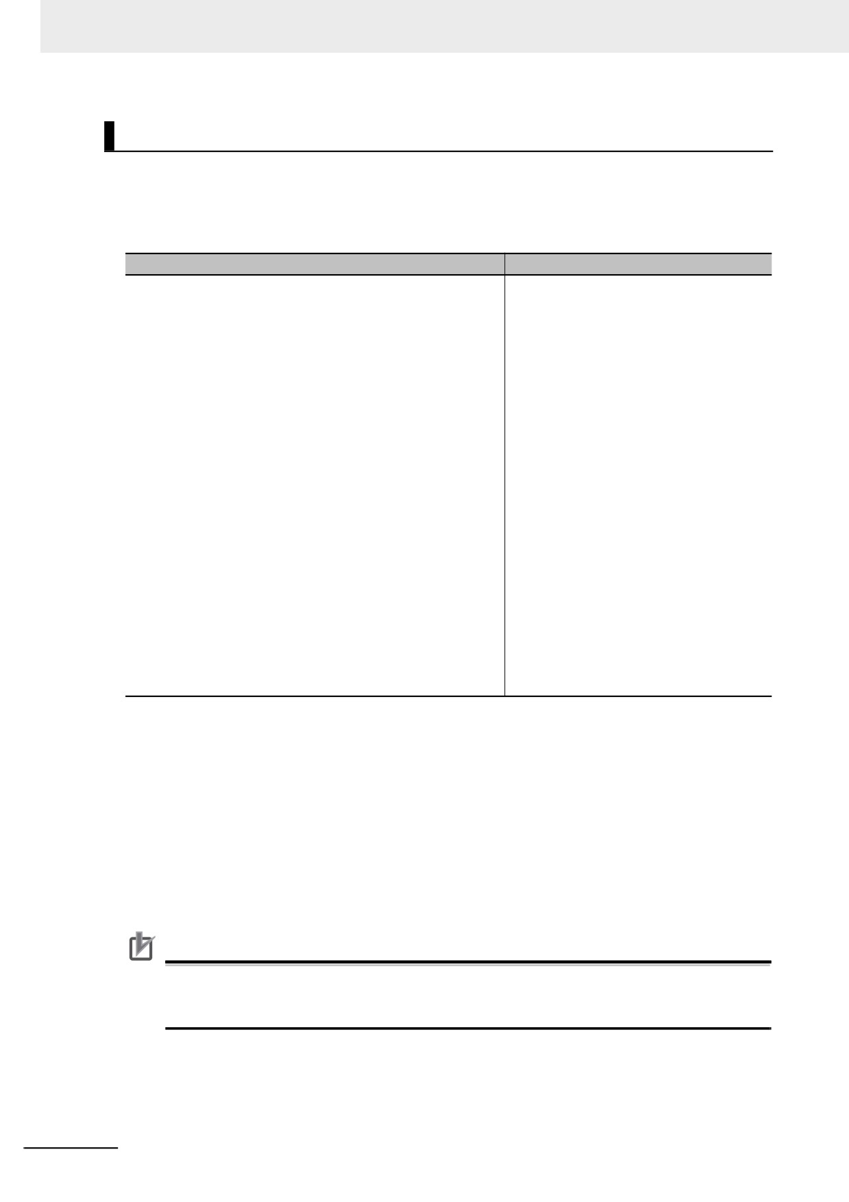
Specifying the Data Groups to Restore
The restore command file allows you to specify the data groups to restore.
You can change the data group specifications by editing the file with a text editor on a computer.
For example, if you change “Variable=yes” on line 8 in the file contents that are shown in the following
table to “Variable=no,” the present values of variables will not be restored.
File contents (defaults when the file is created)
Description
[Restore]
; --- User Program and Configuration. ---
User program and settings
;
Always select "yes".
This data group is always restored.
Always select “yes”.
UserProgram=yes
IP address of built-in EtherNet/IP port
; --- IP Address of Built-in EtherNet/IP Port Settings. ---
yes/no: Restore/Do not restore.
; "yes":will be restored, "no":will not be restored
IPAdr=yes
Present values of variables (only variables
; --- Present values of variables (Retained variables only). ---
that are set to be retained with the Retain
;
"yes":will be restored, "no":will not be restored
attribute)
Variable=yes
yes/no: Restore/Do not restore.
:---Unit/Slave Parameters.---
Units and slaves settings
;
"yes";will be restored."no";will not be restored
yes/no: Restore/Do not restore.
UnitConfig=yes
; --- Absolute encoder home offset. ---
Absolute encoder home offset
;
"yes":will be restored, "no":will not be restored
yes/no: Restore/Do not restore.
AbsEncoder=yes
Note 1
The default file contents when the restore command file is created are given above. All of the data groups
that are listed in the file are set to be restored.
2
The restore command file lists the restorable data groups that were in the backup file when the backup file
was created.
3
Only single-byte alphanumeric characters are used. The text is not case sensitive.
4
An entry of IP Address of Built-in EtherNet/IP Port Settings is not created if the backup is performed in the
Controller with unit version 1.12. In the Controller with unit version 1.14 or later, if an entry of IP Address of
Built-in EtherNet/IP Port Settings for which the restore command file is not created is used, the operation
is performed as “IPAdr=yes”. Refer to Compatibility between Restore Command Files on page 9-37 for
compatibility between the restore command file with unit version 1.12 and the restore command file with
unit version 1.14 or later.
Precautions for Correct Use
When you edit the restore command file, do not change anything in the file except for the “yes”
and “no” specifications for the selectable data groups. If you change anything else in the file, the
Controller may perform unexpected operation when you restore the data.
9-36
9 Backup Functions
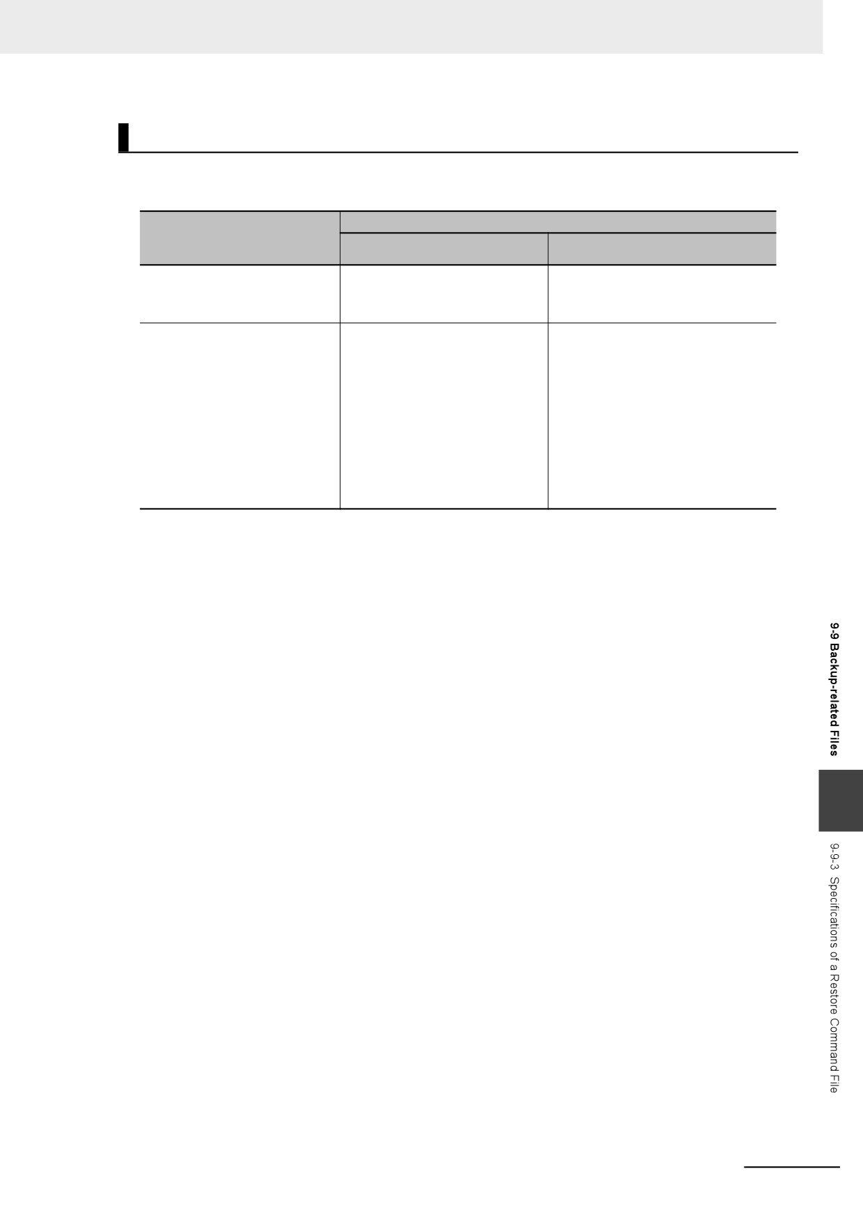
Compatibility between Restore Command Files
The following table shows the compatibility between the restore command file with unit version 1.12
and the restore command file with unit version 1.14 or later.
Unit version of Controller that
Unit version of Controller where data is being restored
creates the restore command
Version 1.12
Version 1.14 or later
file and backup file
Version 1.12
Restorable.
Restorable.
IP Address of Built-in EtherNet/IP
IP Address of Built-in EtherNet/IP
Port Settings is restored.
Port Settings is restored.
Version 1.14 or later
Not restorable.
Restorable.
In the Controller with unit version
IP Address of Built-in EtherNet/IP
1.12, because the entry of IP
Port Settings corresponds to “yes/no”
Address of Built-in EtherNet/IP
of “IPAdr”.
Port Settings cannot be inter-
preted, a Restore Operation
Failed to Start error in an observa-
tion level occurs. The error details
will be “0104 hex: The contents of
the restore command file are not
correct”.
9
9-37
9 Backup Functions
9-9-4
Specifications of a Controller Verification Results File
This section describes the file name, creation timing, created directory, and verification results
confirmation method for a Controller verification results file.
File Name
File
File name
Controller verification results file
VerifyResult.log
File Creation Timing and Created Directories
Function
Procedure
Creation timing
Created directory
SD Memory
SD Memory Card Window in
When verification is executed
Same directory as backup file
Card backups
Sysmac Studio
System-defined variables
When verification is executed
Same directory as backup file
How to Check the Verification Results
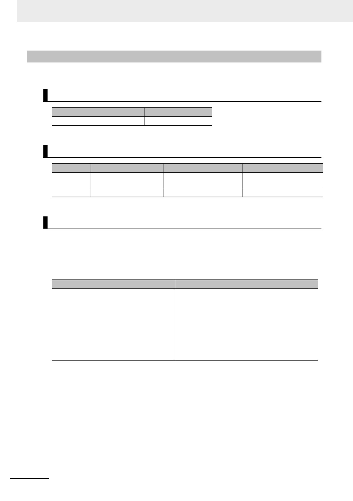
The verification results files contain the results of comparing the Controller data and the data in a
backup file on the Virtual SD Memory Card for each data group. You can check the verification results
in the portion that gives the verification results for each data group. “Result=Matched” indicates a data
group for which no differences were found. “Result=Not matched” indicates a data group for which dif-
ferences were found. In the file shown below, the user program and configuration data matched, and
the Units and slave parameters did not match.
File contents
Description
[UserProgram]
; --- User Program and Configuration. ---
User program and settings
Result=Matched
Matched: No differences were found, Not matched: Dif-
ferences were found.
[UnitConfig]
Units and slaves settings
; --- Unit/Slave Parameters. ---
Matched: No differences were found, Not matched: Dif-
Result=Not matched
ferences were found.
Note 1
The verification results are given only for the data groups that were compared.
2
The verification results of IP Address of Built-in EtherNet/IP Port Settings are including in an entry of user
program and settings even for the Controller with unit version 1.14 or later.
9-38
9 Backup Functions
9-9-5
Specifications of an EtherCAT Verification Results File
This section describes the file name, creation timing, created directory, and verification results confir-
mation method for an EtherCAT verification results file.
File Name
File
File name
EtherCAT verification results file
VerifyResult_ECAT.log
File Creation Timing and Created Directories
Function
Procedure
Creation timing
Created directory
SD Memory
SD Memory Card Window in
When verification is
Same directory as backup file
Card backups
Sysmac Studio
executed
System-defined variables
When verification is
Same directory as backup file
executed
How to Check the Verification Results
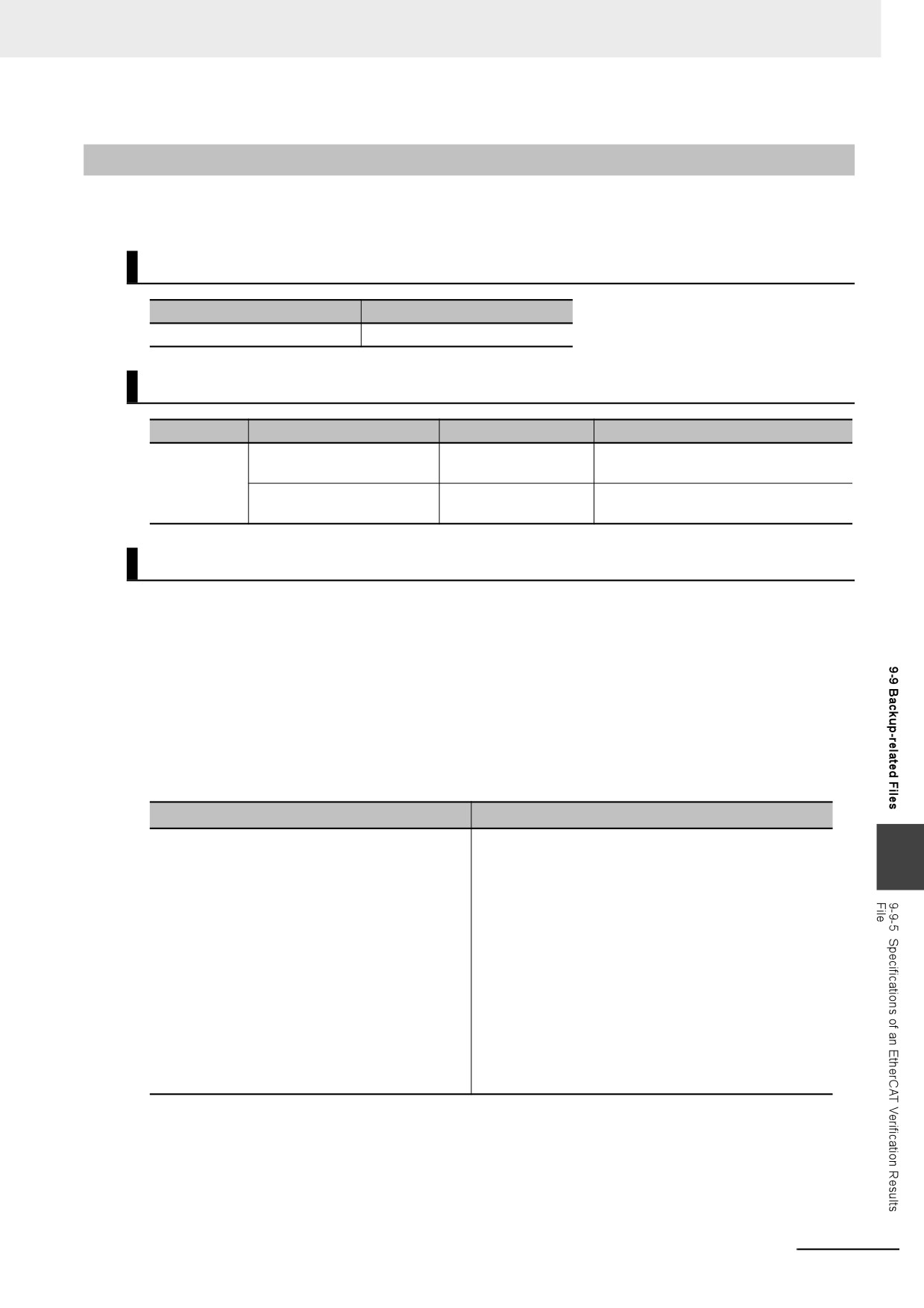
The verification results files contain the results of comparing the Controller data and the data in a
backup file on the Virtual SD Memory Card for each data group.
You can check the verification results in the portion that gives the verification results for each EtherCAT
slave.
“Result=Matched” indicates a data group for which no differences were found. “Result=Not matched”
indicates a data group for which differences were found.
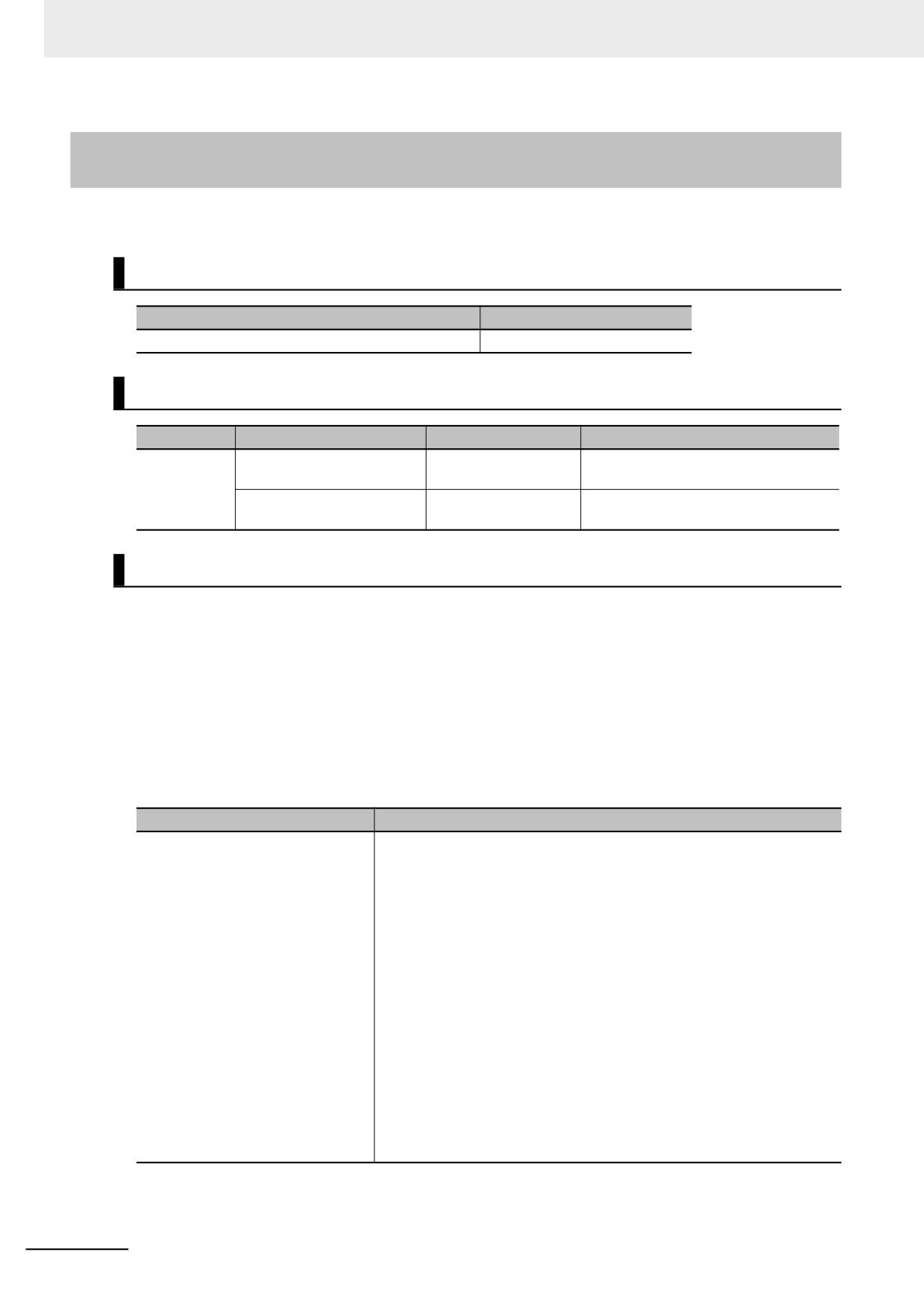
The following table gives an example of the verification results for the following file contents.
• Matched: EtherCAT slave called Master and EtherCAT Slave Terminal E022
• Not matched: EtherCAT slave E001
File contents
Description
[Verification Results]
; --- EtherCAT Parameters. ---
9
: --- See the VerifyResult_ECAT_NX.log about
detail result if NX mark is included in square
brackets.
The slaves are indicated with the user-set device names.
For an EtherCAT Slave Terminal, “:NX” is added to the
[Master]
end of the device name. *1
Result=Matched
The verification results are given as follows:
[E001]
Result=Matched
Same
Result=Not matched
Result=Not matched
Different
Factor=Verification error
[E002:NX]
Result=Matched
*1. If EtherCAT Slave Terminals are set for verification, the EtherCAT Slave Terminal verification results file is
created. The detailed verification results for the EtherCAT Slave Terminals are given in the EtherCAT Slave
Terminal verification results file.
Note The verification results are given only for the EtherCAT slaves that were compared.
9-39
9 Backup Functions
9-9-6
Specifications of an EtherCAT Slave Terminal Verification Results
File
This section describes the file name, creation timing, created directory, and verification results confir-
mation method for an EtherCAT Slave Terminal verification results file.
File Name
File
File name
EtherCAT Slave Terminal verification results file
VerifyResult_ECAT_NX.log
File Creation Timing and Created Directories
Function
Procedure
Creation timing
Created directory
SD Memory
SD Memory Card Window in
When verification is
Same directory as backup file
Card backups
Sysmac Studio
executed
System-defined variables
When verification is
Same directory as backup file
executed
How to Check the Verification Results
The verification results files contain the results of comparing the Controller data and the data in a
backup file on the Virtual SD Memory Card for each data group.
You can check the verification results in the portion that gives the verification results for the EtherCAT
Coupler Units and NX Units.
“Result=Matched” indicates a data group for which no differences were found. “Result=Not matched”
indicates a data group for which differences were found.
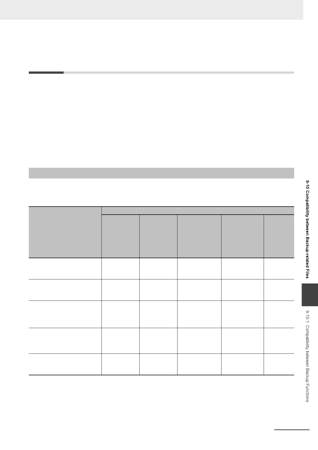
The following table gives an example of the verification results for the following file contents.
• Matched: EtherCAT Coupler Unit E002, NX Unit N1, and NX Unit N2
• Not matched: EtherCAT Coupler Unit E005 and NX Unit N3
File contents
Description
[Verification Results]
The Units are indicated in the following format:
; --- NX Parameters. ---
{Device name}:UnitNo.{Unit number}[blank]{Unit model}
[E002:UnitNo.0 NX-ECC201]
Device Name:
Result=Matched
The device name set by the user.
Unit Number:
[N1:UnitNo.1 NX-AD2203]
Text string of decimal numbers. The value will be between 0 and
Result=Matched
125.
Unit Model:
[N2:UnitNo.2 NX-DA2203]
Text string that identifies the Unit model.
Result=Matched
Consecutive spaces at the end of the model number are deleted.
[N3:UnitNo.3 NX-TS3201]
The verification results are given as follows:
Result=Not matched
Result=Matched
Same
Factor=Verification error
Result=Not matched
Different
[E005:UnitNo.0 NX-ECC201]
Result=Not matched
Factor=Verification error
9-40
9 Backup Functions
9-10 Compatibility between Backup-
related Files
The files may not be compatible if you back up and restore data under different conditions.
The files may not be compatible in these three cases:
• When the function that was used to back up data is different from the function that was used to
restore it.
• When the model number of the Controller where the data was backed up from does not match the
model number where data is being restored.
• When the unit versions of the Controller, other Units, or slaves where the data was backed up
from do not match the unit versions where data is being restored.
In this context, the term “restore” is used collectively for these backup functions: restore, automatic
transfer, and read (back up).
9-10-1
Compatibility between Backup Functions
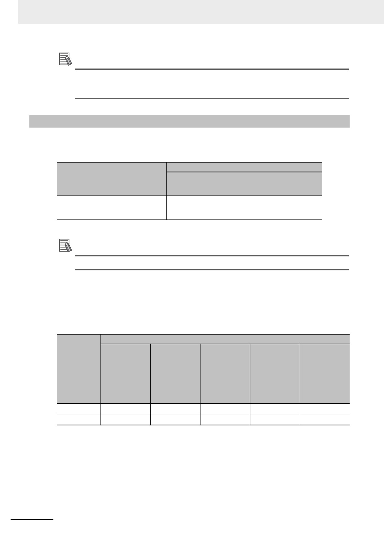
The following table shows the file compatibility when the function used to back up the data is different
from the function used to restore it.
(C: Compatible, N: Not compatible.)
Function used to restore data
Restoring with
Restoring with
Restoring with
Restoring with
Importing
SD Memory
Sysmac Stu-
Controller
Sysmac Studio
Sysmac
Function used to back up
Card backup
dio Controller
backup functions
variable and
Studio
data
functions
backup func-
for Industrial PC
memory backup
backup file
(SD Memory
tions
Support Utility
functions
data (com-
Card to Con-
(computer to
(Windows to
(computer to
puter to
troller)
Controller)
Controller)
Controller)
project)
Backing up with SD Memory
C
C
C
N
C*1
Card backup functions
(Controller to SD Memory Card)
Backing up with Sysmac Studio
C
C
C
N
C*1
Controller backup functions
9
(Controller to computer)
Backing up with Controller
C
C
C
N
C*1
backup functions for Industrial
PC Support Utility
(Controller to Windows)
Backing up with Sysmac Studio
N
N
N
C
N
variables and memory data
backup functions
(Controller to computer)
Exporting from a Sysmac Studio
C*1
C*1
C*1
N
C
backup file
(project to computer)
*1. The following data is not included.
The built-in EtherNet/IP port name and built-in EtherNet/IP tag data link settings in the Controller Setup
Operation authority verification
Data Trace Settings
Present values of variables
Absolute encoder home offsets
9-41
9 Backup Functions
Additional Information
The files that are handled for backing up variables and memory from the Sysmac Studio are not
compatible with other backup files. Refer to 9-6 Sysmac Studio Variable and Memory Backup
Functions for details on these functions.
9-10-2
Compatibility between NY-series Controller Models
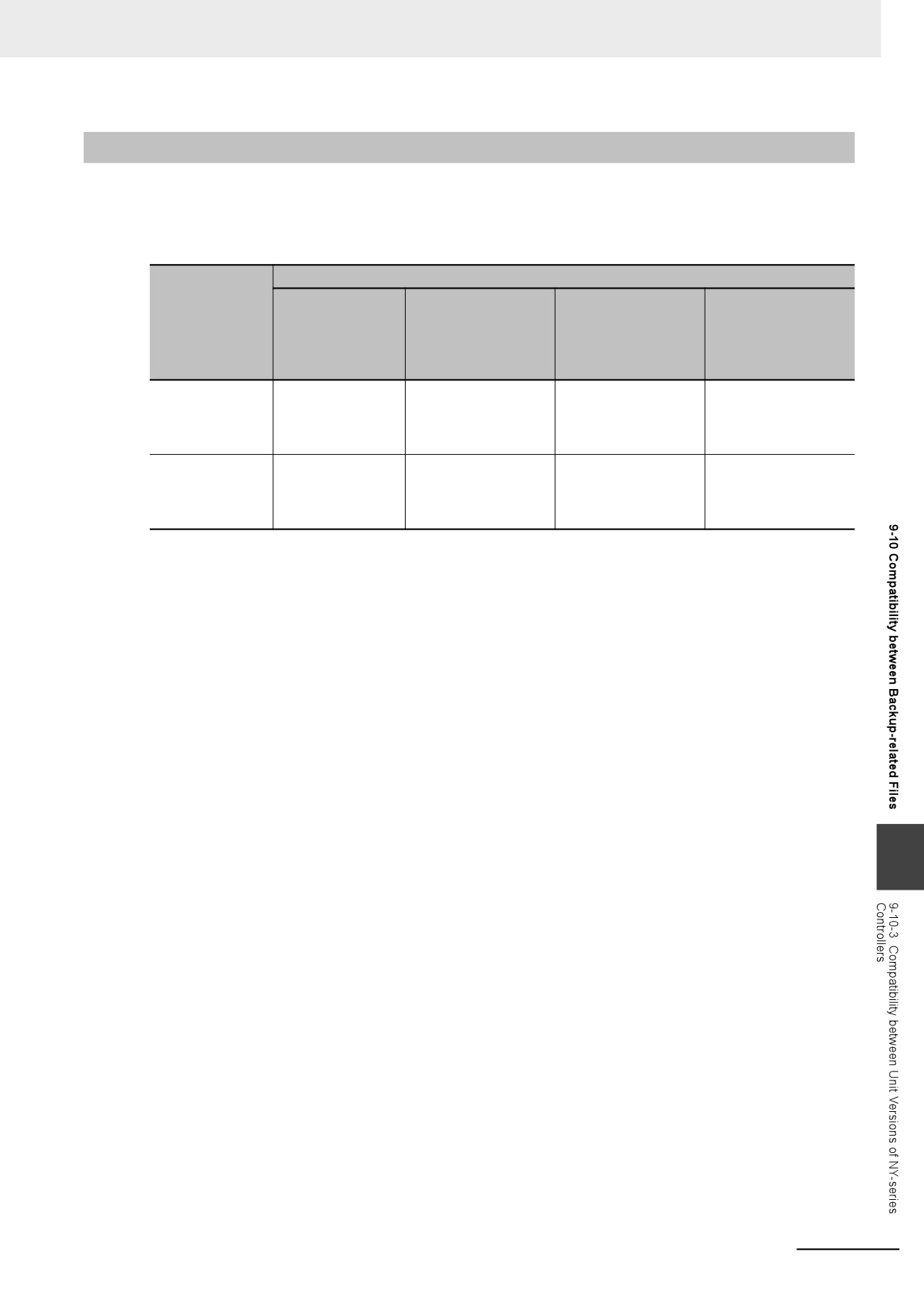
The following table shows the file compatibility when the Controller model where the data was backed
up from is different from the group where the data is being restored.
(C: Compatible, N: Not compatible.)
Controller model to restore to
Controller model where data was
NY52-1500
backed up
NY52-1400
NY52-1300
NY52-1500
NY52-1400
C
NY52-1300
Additional Information
NC Integrated Controller are not compatible.
Even if the Controller models are compatible, there may be restrictions between various Controller
models.
The following table shows which restoration function can be used based on whether the Controller
models are compatible.
(R: Restored, x: Not restored)
Function used to restore data
Restoring with
Restoring with
Restoring with
Restoring with
Controller
Sysmac Studio
Sysmac Studio
Importing Sys-
Compatibility
SD Memory
backup func-
Controller
variable and
mac Studio
between Con-
Card backup
tions for Indus-
backup func-
memory backup
backup file data
troller models
functions (SD
trial PC Support
tions (com-
functions (com-
(computer to
Memory Card to
Utility
puter to
puter to Con-
project)
Controller)
(Windows to
Controller)*1
troller)
Controller)
Compatible
R*2
R
R
R
R
Not compatible
x*3
x
x
x
x
*1. Only the files that were backed up using this function can be restored.
*2. If the contents of the backup file are outside the range of specifications where the data is restored, the Controller
will not operate normally. When you operate the Controller, a major fault level Controller error or a partial fault
level Controller error will occur. For example, this error occurs if the number of controlled axes that is used is
outside the specifications.
*3. A Restore Start Failed observation will occur.
9-42
9 Backup Functions
9-10-3
Compatibility between Unit Versions of NY-series Controllers
The following table shows the compatibility of backup files when the unit versions of the Controller are
different between where the data was backed up and where it is being restored. You can restore data
without any restrictions if the unit versions are the same before and after the backup and restoration.
(R: Restored, x: Not restored)
Function used to restore data
Restoring with SD
Restoring with Control-
Restoring with Sysmac
Restoring with Sysmac
Unit version of
Memory Card
ler backup functions for
Studio variable and
Studio Controller
Controller
backup functions
Industrial PC Support
memory backup func-
backup functions (com-
(SD Memory Card to
Utility
tions (computer to Con-
puter to Controller)
Controller)
(Windows to Controller)
troller)
Unit version of
R
R
R
R
Controller where
data is being
restored is newer.
Unit version of
x
x
x
R
Controller where
data is being
restored is older.
9
9-43
9 Backup Functions
9-11
Functions That Cannot Be Executed
during Backup Functions
The following functions cannot be executed at the same time as any of the backup functions. Do not
execute any backup function while the Controller is executing any of these functions. Also, do not exe-
cute any of these functions during execution of any of the backup functions.
• While a backup function is being performed
• Synchronization transfer from the computer to the Controller
• Execution of online editing
• Execution of Memory All Clear operation
• Execution of the Save Cam Table instruction (MC_SaveCamTable)
• Execution of CPU Unit name write operation
• Execution of transferring Slave Terminal parameters
9-44

10
Communications Setup
This section describes how to go online with the NY-series Controller and how to con-
nect to other devices.
10-1 Communications System Overview
10-2
10-1-1
Introduction
10-3
10-2 Connection with Sysmac Studio
10-4
10-2-1
Configurations That Allow Online Connections
10-4
10-2-2
Configurations That Do Not Allow Online Connections
10-5
10-3 Connection with Other Controllers or Slaves
10-6
10-3-1
Connection Configurations between Controllers
10-6
10-3-2
Connection Configuration between Controllers and Slaves
10-9
10-4 Connection with HMIs
10-10
10-1
10 Communications Setup
10-1 Communications System Overview
This section gives an overview of the communications systems that are supported by NY-series Con-
trollers.
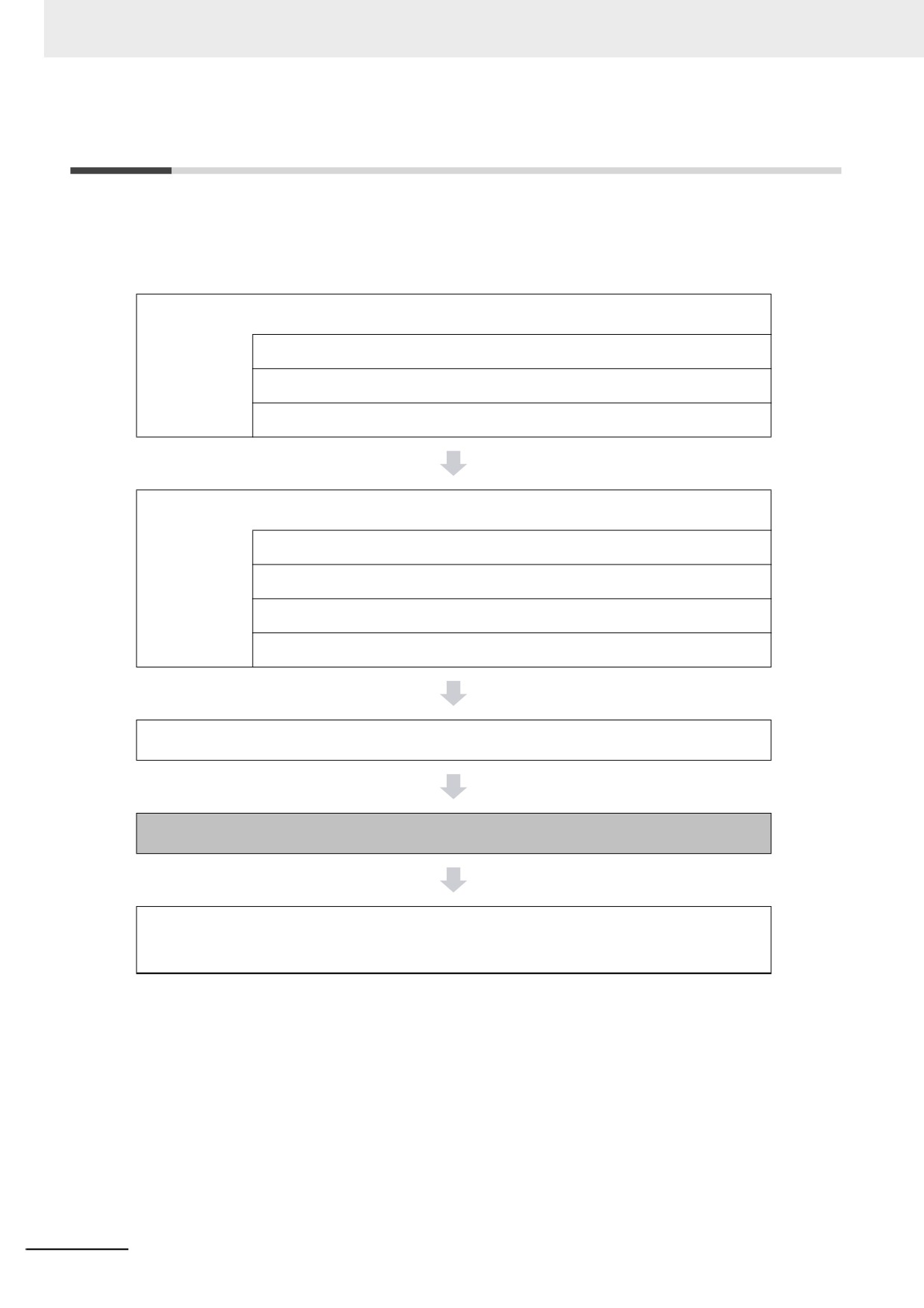
The shaded steps in the overall procedure that is shown below are related to the communications sys-
tems.
Step 1. Software Design
Step 1-1 Designing I/O and Processing
Step 1-2 Designing Tasks
Step 1-3 Designing Programs
Step 2. Software Setups and Programming
Step 2-1 Slave and Unit Configurations
Step 2-2 Controller Setup
Step 2-3 Programming
Step 2-4 Offline Debugging
Step 3. Mounting and Setting Hardware
Step 4. Wiring
Step 5. Checking Operation and Starting Operation on the
Actual System
Refer to 1-4 Overall Operating Procedure for the NY-series Controller for details.
10-2
10 Communications Setup
10-1-1
Introduction
z NY-series System
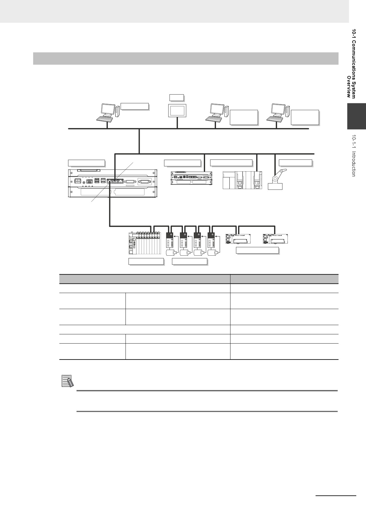
You can use the NY-series System to build the communications system shown below.
HMI
Sysmac Studio
SCADA
BOOTP server
MES/ERP
DNS server
10
EtherNet/IP
EtherNet/IP
Built-in EtherNet/IP port
NY-series Controller
NY-series Controller
NJ/NX-series Controller
EtherNet/IP slave
Built-in EtherCAT port
EtherCAT
General-purpose slaves
Slave Terminal
Servo Drives
Connection
Connection method
Sysmac Studio connection
Use the built-in EtherNet/IP port.
Connections between
Connections with NJ/NX/NY-series Con-
Use the built-in EtherNet/IP port.
Controllers
troller
Connections between
Connections to Servo Drives and gen-
Use the built-in EtherCAT port.
Controllers and slaves
eral-purpose slaves
Connections to HMIs
Use the built-in EtherNet/IP port.
Connections to systems
Connections to SCADA, MES/ERP
Use the built-in EtherNet/IP port.
Connections to servers
Connections to FTP servers, BOOTP
Use the built-in EtherNet/IP port.
servers, or DNS servers
Additional Information
Refer to the NY-series Industrial Panel PC / Industrial Box PC Setup User's Manual (Cat. No.
W568) for information on the communications system that can be used in Windows.
10-3
10 Communications Setup
10-2 Connection with Sysmac Studio
This section describes the configurations for connecting the Sysmac Studio to an NY-series Controller.
10-2-1
Configurations That Allow Online Connections
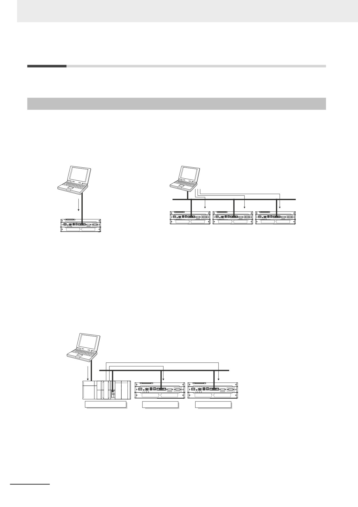
You can connect online from the Sysmac Studio to a built-in EtherNet/IP port of the NY-series Control-
ler.
z Connecting with EtherNet/IP
1:1 Connection
1:N Connections
Sysmac Studio
Sysmac Studio
EtherNet/IP
EtherNet/IP
Built-in EtherNet/IP port
Built-in EtherNet/IP port
• A direct connection is made from the com-
• Specify the IP address of the remote node from the Sysmac
puter that runs Sysmac Studio. You do not
Studio.
need to specify the IP address or connec-
• You can use either a cross cable or a straight cable.
tion device.
• You can make the connection either with or
without a Ethernet switch.
• You can use either a cross cable or a
straight cable.
z Connecting to EtherNet/IP through USB
You can connect to the NY-series built-in EtherNet/IP port through a USB port of the NJ/NX-series
Controller.
Sysmac Studio
USB
EtherNet/IP
NJ/NX-series Controller
NY-series Controller
NY-series Controller
• Specify the IP address of the remote node from the Sysmac Studio.
• You can use either a cross cable or a straight cable.
Note Connect a computer and the NJ/NX-series CPU Unit with a USB 2.0 certified cable. Do not use a USB hub
to connect them.
10-4
10 Communications Setup
10-2-2
Configurations That Do Not Allow Online Connections
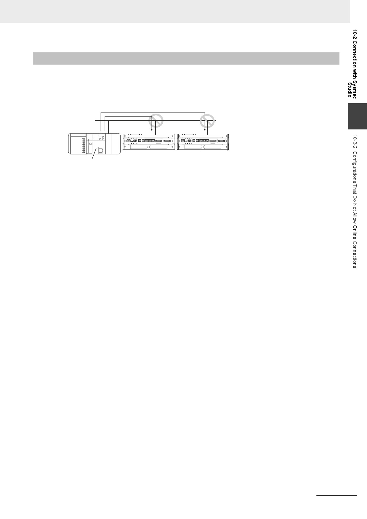
z Routing through CS/CJ-series EtherNet/IP Units/Ports
You cannot connect to an NY-series Controller by routing through a CS/CJ-series Ethernet/IP Unit or
port (CS1W-EIP2, CJ1W-EIP21, CJ2 CPU Unit built-in EtherNet/IP port, or CJ2M CPU Unit built-in
EtherNet/IP port).
10
EtherNet/IP
CJ2 CPU Unit built-in EtherNet/IP port or EtherNet/IP Units
10-5