Omron IPC Machine Controller Industrial Panel PC / Industrial Box PC. Software User’s Manual (Industrial PC Platform NY-series) - page 17
Appendices
Percent of
Percent of
execution
Types of instructions
Instructions
instructions
time in
[%]
instruction
group [%]
Bit string processing instructions
AND and OR
6.2%
13.0%
Data movement instructions
MOVE
4.6%
23.5%
Total
100.0%
100.0%
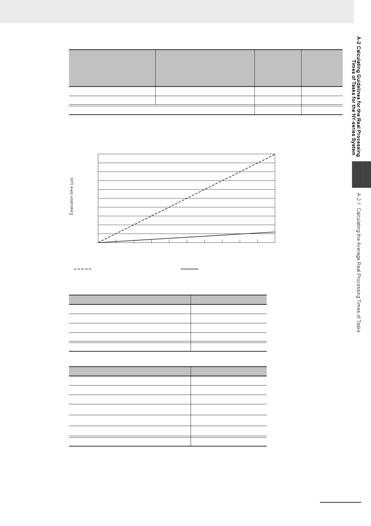
Execution Times for Ladder Diagram Arithmetic and Trigonometric
Instructions for LREAL Data
300
270
240
A
210
NY5
2-
180
150
120
90
60
NY5
2-
30
0
0
300
600
900
1200
1500
1800
2100
2400
2700
3000
Total number of instructions
Trigonometric instructions for LREAL data
Arithmetic instructions for LREAL data
• Configuration of Arithmetic Instructions for LREAL Data
Instructions
Percent of instructions [%]
Addition instructions for LREAL data
20.0%
Subtraction instructions for LREAL data
20.0%
Multiplication instructions for LREAL data
30.0%
Division instructions for LREAL data
30.0%
Total
100.0%
• Configuration of Trigonometric Instructions for LREAL Data
Instructions
Percent of instructions [%]
Sin of LREAL data
16.7%
Cos of LREAL data
16.7%
Tan of LREAL data
16.7%
Sin−1 of LREAL data
16.7%
16.7%
Cos−1 of LREAL data
Tan−1 of LREAL data
16.7%
Total
100.0%
A-17
Appendices
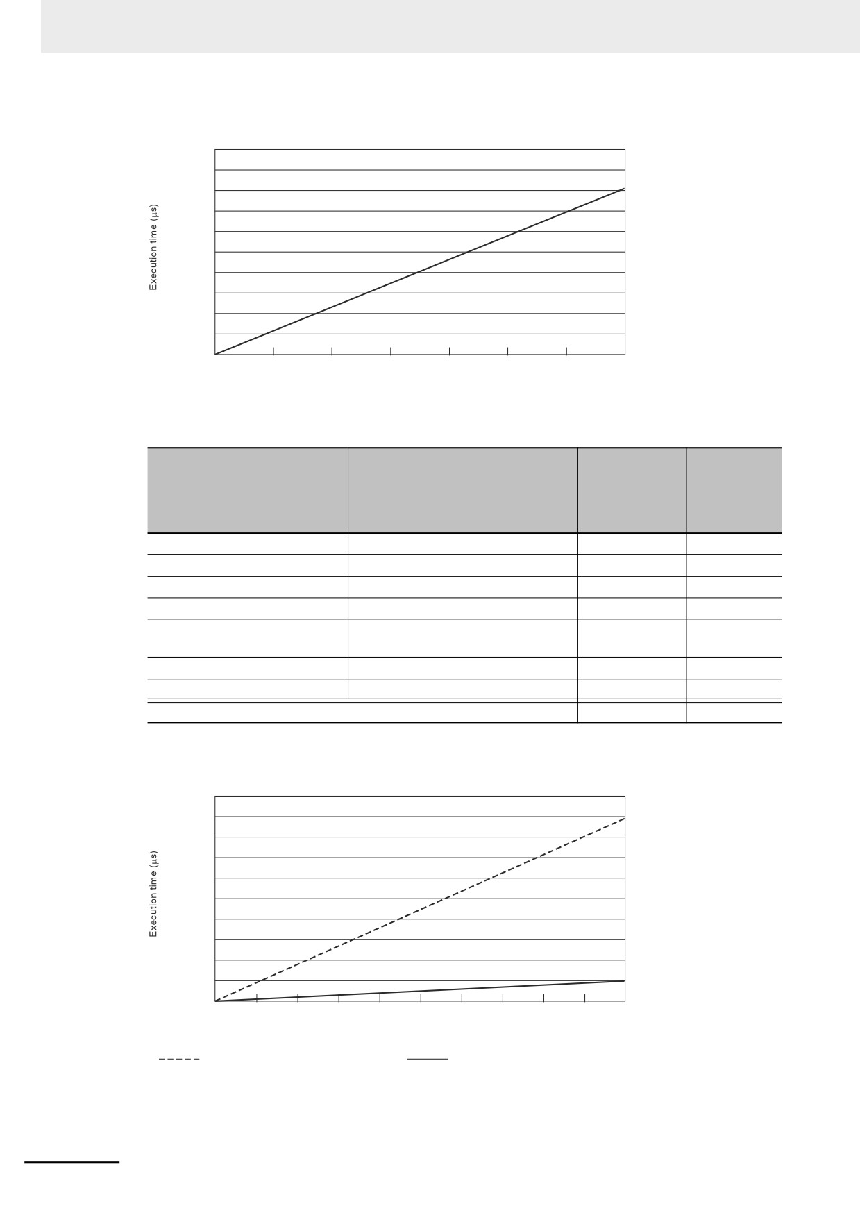
Execution Time for Standard ST Instructions
1000
900
800
700
600
500
NY5
2-
400
300
200
100
0
0
10000
20000
30000
40000
50000
60000
70000
Total number of instructions
• Instruction Configuration for Standard ST Instructions
Percent of
Percent of
execution
Types of instructions
Instructions
instructions
time in
[%]
instruction
group [%]
ST constructs
IF ELSIF END_IF
75.4%
41.6%
Comparison instructions
EQ and LT
5.2%
8.7%
Timer and counter instructions
Timer, TON/TOF, and CTU/CTD
2.1%
18.8%
Math instructions
+, -, *, and /
3.1%
10.2%
BCD conversion instructions and
INT_TO_DINT and WORD_BC-
0.2%
1.6%
data conversion instructions
D_TO_UINT
Bit string processing instructions
AND and OR
8.0%
11.7%
Data movement instructions
:=
5.9%
7.3%
Total
100.0%
100.0%
Execution Times for ST Arithmetic and Trigonometric Instructions for LREAL
Data
300
270
240
210
NY5
2-
180
150
120
90
60
NY5
2-
30
0
0
300
600
900
1200
1500
1800
2100
2400
2700
3000
Total number of instructions
Trigonometric instructions for LREAL data
Arithmetic instructions for LREAL data
A-18
Appendices
• Configuration of Arithmetic Instructions for LREAL Data
Instructions
Percent of instructions [%]
Addition instructions for LREAL data
20.0%
Subtraction instructions for LREAL data
20.0%
Multiplication instructions for LREAL data
30.0%
Division instructions for LREAL data
30.0%
Total
100.0%
• Configuration of Trigonometric Instructions for LREAL Data
Instructions
Percent of instructions [%]
Sin of LREAL data
16.7%
Cos of LREAL data
16.7%
Tan of LREAL data
16.7%
Sin−1 of LREAL data
16.7%
A
16.7%
Cos−1 of LREAL data
Tan−1 of LREAL data
16.7%
Total
100.0%
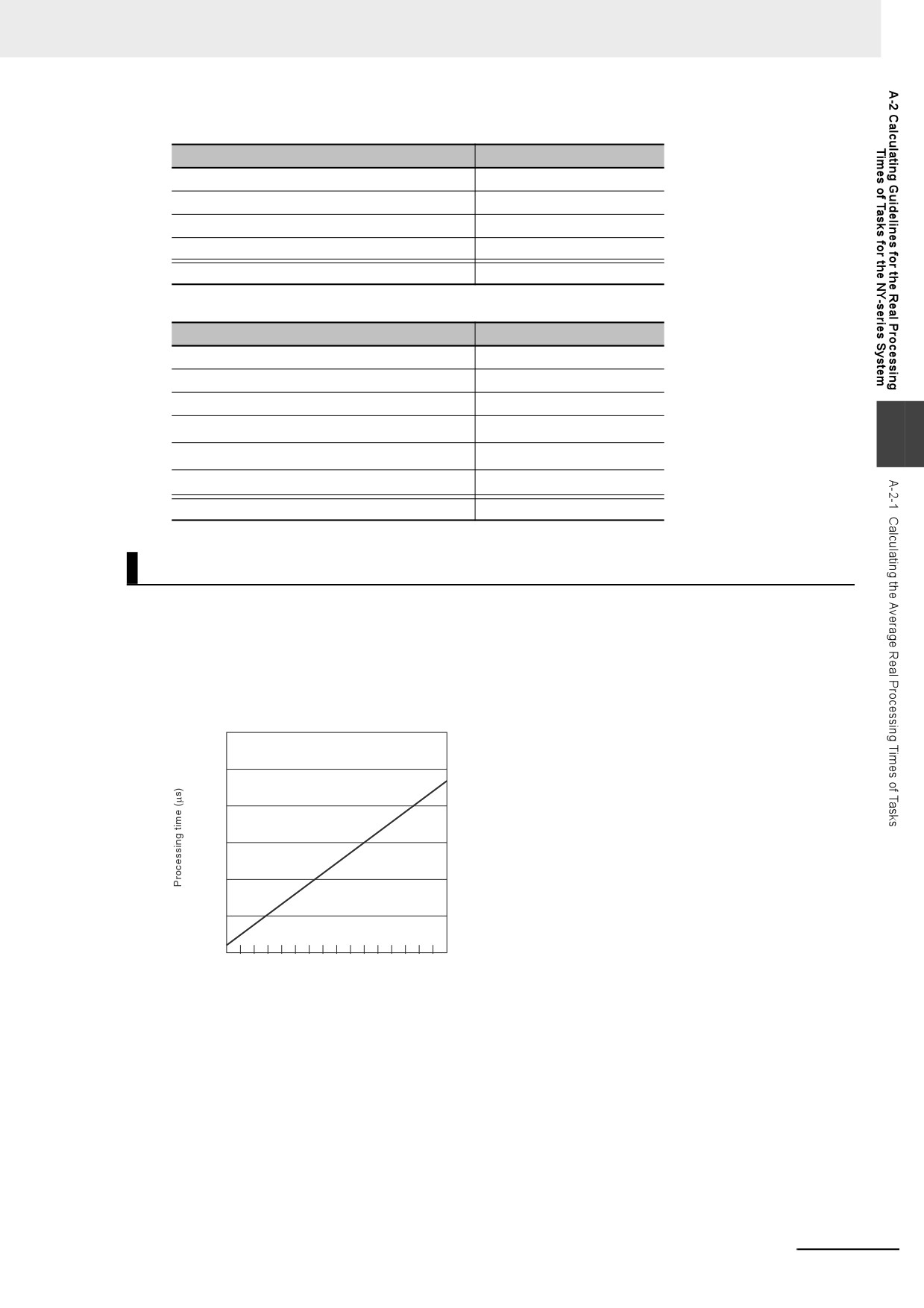
Motion Control Processing Time
The motion control processing time depends on the number of servo axes and virtual servo axes that
are used.
For the number of servo and virtual servo axes, read the motion control processing time from the follow-
ing graph.
NY5
2-
90
75
60
45
30
15
0
0
8
16
24
32
40
48
56
64
Number of axes
A-19
Appendices
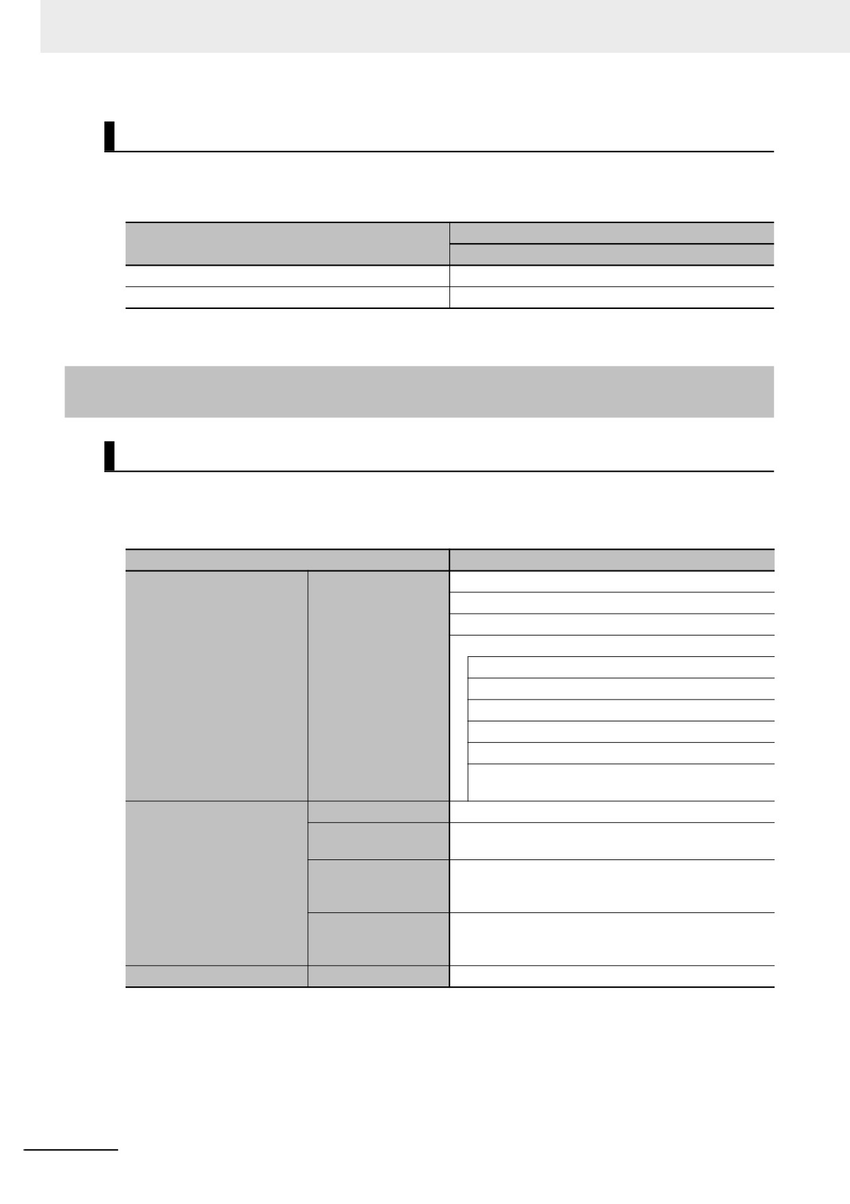
Common Processing Time
The common processing time is the following values by the total time for system overhead, system
common processing 1, and system common processing 2. The common processing time depends on
the type of task.
Common processing times [μs] (reference values)
Type of task
NY52-
Primary periodic task
258
Priority-16, 17, or 18 periodic task
20
A-2-2
Example of Calculating the Average Real Processing Time of a
Task and Setting the Task Period
Example of Calculating the Average Real Processing Times of Tasks
If you are using an NY52- Controller with a unit version of 1.12, first find the average real pro-
cessing time of the task for the following conditions.
The task is the primary periodic task.
Item
Conditions
GX-ID1611 (Ver. 1.1) Input Slave: 1
GX-OD1611 (Ver. 1.1) Output Slave: 1
R88D-1SN-ECT Servo Drives: 4
EtherCAT Slave Terminal: 1
NX-ECC203 EtherCAT Coupler Unit: 1
Slaves/Units that are used
EtherCAT slaves
NX-ID5342 DC Input Unit: 1
NX-OD5121 Transistor Output Unit: 1
NX-AD3608 Analog Input Unit: 1
NX-DA2605 Analog Output Unit: 1
NX-CIF101 and NX-CIF105 Communications Inter-
face Units: 1 per Unit
Language
Ladder diagrams
Standard instruction
Number of instructions: 5,000
configuration
Arithmetic
Number of instructions: 200
User program
instructions for
LREAL data
Trigonometric
Number of instructions: 100
instructions for
LREAL data
Motion control processing
Number of axes
4
Note Total length of cables connected to the built-in EtherCAT port is 10 [m].
A-20
Appendices
z I/O Refresh Time
EtherCAT slave processing time:
The following table gives the pDout (output processing data size), pDin (input processing data size),
and pDinout (larger of the input and output data size) values of the GX-ID1611 (Ver. 1.1) Input
Slave, GX-OD1611 (Ver. 1.1) Output Slave, R88D-1SN-ECT Servo Drives, and EtherCAT
Slave Terminal configured with Units shown above.
pDout: Output
pDinout: Larger of
pDin: Input process-
EtherCAT slave
processing data size
the input and output
ing data size in bytes
in bytes
data size
GX-ID1611 (Ver. 1.1)
0
3
3
GX-OD1611 (Ver. 1.1)
2
1
2
R88D-1SN-ECT
23
26
26
EtherCAT Slave Terminal (Total)
62
88
88
A
NX-ECC203
0
18
NX-ID5342
0
2
NX-OD5121
2
0
---
NX-AD3608
0
8
NX-DA2605
4
0
NX-CIF101
28
30
NX-CIF105
28
30
Total number of bytes are given below for pDout, pDin and pDinout.
pDout = 2 + 23 × 4 + 62 = 156 [byte]
pDin = 3 + 1 + 26 × 4 + 88 = 196 [byte]
pDinout = 3 + 2 + 26 × 4 + 88 = 197 [byte]
From these values, the I/O refresh time is calculated by the following formula.
I/O refresh processing time
= EtherCAT slave processing time
= 0.0008 × pDout + 0.0028 × pDin + 0.082 × pDinout + (1.24 × Snum + 0.01 × Clen)
= 0.0008 × 156 + 0.0028 × 196 + 0.082 × 197 + (1.24 × 7 + 0.01 × 10)
= 0.1248 + 0.5488 + 16.154 + (8.68 + 0.1)
≈ 26 [μs]
z User Program Execution Time
The graphs show the following values.
• Standard instruction configuration
From the graph of the execution time for standard ladder diagram instructions, the user program
execution time of 5,000 instructions for the NY52- is 16.5 μs.
• Arithmetic instructions for LREAL data
From the graph of the execution time for ladder diagram arithmetic and trigonometric instructions
for LREAL data, the user program execution time of 200 instructions for the NY52- is
2.5 μs.
A-21
Appendices
• Trigonometric instructions for LREAL data
From the graph of the execution time for ladder diagram arithmetic and trigonometric instructions
for LREAL data, the user program execution time of 100 instructions for the NY52- is 10
μs.
Therefore, the user program execution time is the total of the above values, which is given by the fol-
lowing formula.
User program execution time = 16.5 + 2.5 + 10
= 29 [μs]
z Motion Control Processing Time
From the graph of the execution time for motion control processing, the execution time of the motion
control processing for four axes for the NY52- is read as 7 μs.
z Common Processing Time
Because the task is the primary periodic task, the common processing time for the NY52-
is 258 μs.
Therefore, the average real processing time of the task is given by the following formula.
Average real processing time of task = I/O refresh processing time + User program execution time
+ Motion control processing time + Common processing time
= 26 + 29 + 7 + 258
= 320 [μs]
Setting the Task Period
The task period is set based on the average real processing time of the task that is calculated as above.
The task is the primary periodic task.
The value of the task period must be larger than the average real processing time of the task that you
calculated. More specifically, you should allow sufficient margin and set the task period value to at least
1.1 times as large as the average real processing time of the task.
Task period ≥ Average real processing time of task × 1.1
Because the average real processing time of the task that is calculated above is 320 μs, the task period
is set to 500 μs, which is larger than 1.1 times the average time.
The task execution times in the physical Controller depends on the logic operations that are performed
in the user program, the presence of communications commands and data links, on whether data trac-
ing is performed, the load on Windows, the connection of Industrial Monitors, the usage of PCIe cards,
and on other factors. The task execution time for a periodic task depends on whether it is interrupted for
the execution of tasks with higher execution priorities.
Use the physical Controller and verify the task execution time with the Task Execution Time Monitor.
A-22
Appendices
A-3
System-defined Variables
System-defined variables are assigned specific functions by the system. They are registered in the
global variable table, or the local variable table for each POU, in advance.
These variables cannot be changed. Some of the variables start with an underbar and some start with
”P_”.
Some of the system-defined variables are read-only and some are read/write.
You read and write the variables with the user program, with communications from external devices,
with the Sysmac Studio, or with an NS/NA-series PT.
Basically, system-defined variables are classified according to the function modules. The variables start
with the following category names.
Function module
Category name
A
System-defined variables for the overall NY-
None
series Controller
PLC Function Module
_PLC
Motion Control Function Module
_MC
EtherCAT Master Function Module
_EC
EtherNet/IP Function Module
_EIP, _EIP1, and _EIPIn1
The variables are described in the tables of this appendix as shown below.
Range of
Variable name
Meaning
Function
Data type
Reference
values
This is the system-
This is the mean-
The function of the variable is described.
The data
The range of
The page of
defined variable
ing of the vari-
type of the
values that the
the individual
name. The prefix
able.
variable is
variable can
system-
gives the category
given.
take is given.
defined vari-
name.
able specifi-
cations table
is given.
A version in parentheses in the Variable name column is the unit version of the NY-series Controller
when the system-defined variable was added.
Precautions for Correct Use
There are system-defined variables that are not supported or differ in specifications such as the
number of arrays. Refer to A-4 Specifications for Individual System-defined Variables for details on the
specifications for individual system-defined variables.
A-23

Appendices
A-3-1
System-defined Variables for the Overall NY-series Controller
(No Category)
z Functional Classification: Clock
Range of
Variable name
Meaning
Function
Data type
Reference
values
_CurrentTime
System Time
Contains the Controller’s internal clock
DATE_
DT#2000-01-
page A-53
data.
AND_
01-00:00:00 to
TIME
DT#2099-12-
31-23:59:59
z Functional Classification: Tasks
Range of
Variable name
Meaning
Function
Data type
Reference
values
_TaskName_
Task Active Flag
TRUE during task execution.
BOOL
TRUE or
page A-53
Active
FALSE
FALSE when task execution is not in prog-
ress.
Note You cannot use this system-defined
variable in the user program. It is
used only to access task status for
data tracing from the Sysmac Stu-
dio.
_TaskName_
Last Task
Contains the task execution time the last
TIME
Depends on
page A-53
LastExecTime
Execution Time
time the task was executed (unit: 0.1 μs).
data type.
Note You cannot use this system-defined
variable in the user program. It is
used only to access task status for
data tracing from the Sysmac Stu-
dio.
_TaskName_
Maximum Task Exe-
Contains the maximum value of the task
TIME
Depends on
page A-54
MaxExecTime
cution Time
execution time (unit: 0.1 μs).
data type.
Note You cannot use this system-defined
variable in the user program. It is
used only to access task status for
data tracing from the Sysmac Stu-
dio.
_TaskName_
Minimum Task Execu-
Contains the minimum value of the task
TIME
Depends on
page A-54
MinExecTime
tion Time
execution time (unit: 0.1 μs).
data type.
Note You cannot use this system-defined
variable in the user program. It is
used only to access task status for
data tracing from the Sysmac Stu-
dio.
_TaskName_
Task Execution Count
Contains the number of executions of the
UDINT
Depends on
page A-54
ExecCount
task.
data type.
If 4294967295 is exceeded, the value
returns to 0 and counting is continued.
Note You cannot use this system-defined
variable in the user program. It is
used only to access task status for
data tracing from the Sysmac Stu-
dio.
_TaskName_
Task Period
TRUE if the task period was exceeded.
BOOL
TRUE or
page A-54
Exceeded
Exceeded Flag
FALSE
FALSE if task execution was completed
within the task period.
Note You cannot use this system-defined
variable in the user program. It is
used only to access task status for
data tracing from the Sysmac Stu-
dio.
A-24
Appendices
Range of
Variable name
Meaning
Function
Data type
Reference
values
_TaskName_
Task Period
Contains the number of times that the
UDINT
Depends on
page A-55
ExceedCount
Exceeded Count
period was exceeded.
data type.
If the present value exceeds the maximum
value of the data type, the present value
returns to 0 and the count is continued.
If 4294967295 is exceeded, the value
returns to 0 and counting is continued.
Note You cannot use this system-defined
variable in the user program. It is
used only to access task status for
data tracing from the Sysmac Stu-
dio.
z Functional Classification: Errors
Range of
Variable name
Meaning
Function
Data type
Reference
values
A
_ErrSta
Controller Error
TRUE if there is a Controller error.
WORD
16#0000 to
page A-55
Status
16#C0F0
FALSE if there is no Controller error.
Note Do not use this variable in the user pro-
gram. There may be a delay in updat-
ing it and concurrency problems in
relation to the error status of the func-
tion module. Use this variable only to
access status through communications
from an external device. Refer to infor-
mation on the meanings of the error
status bits at the end of this appendix
for details.
_AlarmFlag
User-defined
The bit corresponding to the event level is
WORD
16#0000 to
page A-55
Error Status
TRUE while there is a user-defined error. Bits
16#00FF
00 to 07 correspond to user fault levels 1 to 8.
This variable contains 0000 hex when there is
no user-defined error.
A-25

Appendices
z Functional Classification: SD Memory Card
Range of
Variable name
Meaning
Function
Data type
Reference
values
_Card1Ready
SD Memory Card
TRUE when the Virtual SD Memory Card is
BOOL
TRUE or
page A-56
Ready Flag
recognized in an NY-series Controller.
FALSE
FALSE when the Virtual SD Memory Card is
not recognized.
TRUE: The Card can be used.
FALSE: The Card cannot be used.
_Card1Protect
SD Memory Card
The NY-series Controller does not use this
BOOL
TRUE or
page A-56
Write
variable.
FALSE
Protected Flag
The value is always FALSE.
_Card1Err
SD Memory Card
The NY-series Controller does not use this
BOOL
TRUE or
page A-56
Error Flag
variable.
FALSE
The value is always FALSE.
_Card1Access
SD Memory Card
The NY-series Controller does not use this
BOOL
TRUE or
page A-56
Access Flag
variable.
FALSE
The value is always FALSE.
_Card1Deteriorated
SD Memory Card
The NY-series Controller does not use this
BOOL
TRUE or
page A-56
Life
variable.
FALSE
Warning Flag
The value is always FALSE.
_Card1PowerFail
SD Memory Card
TRUE when the power supply to the Control-
BOOL
TRUE or
page A-57
Power Interrup-
ler was interrupted during access to the Vir-
FALSE
tion Flag
tual SD Memory Card.
TRUE: Power was interrupted during Virtual
SD Memory Card access.
FALSE: Normal
_Card1Capacity
SD Memory Card
Show the total capacity of the Virtual SD
UDINT
Depends on
page A-57
Storage Capacity
Memory Card.
data type.
(Ver.1.21)
The unit of capacity is MiB (1 MiB=1,048,576
bytes).
The value is updated every 60 seconds.
If the Virtual SD Memory Card is disabled, the
value is “0”.
_Card1Used
SD Memory Card
Show the usage of the Virtual SD Memory
UDINT
Depends on
page A-57
Storage Usage
Card.
data type.
(Ver.1.21)
The unit of capacity is MiB (1 MiB=1,048,576
bytes).
The value is updated every 60 seconds.
If the Virtual SD Memory Card is disabled, the
value is “0”.
A-26
Appendices
Variable name
Range of
Meaning
Function
Data type
Reference
Member name
values
_Card1BkupCmd
SD Memory Card
_sBKUP_
page A-57
Backup Com-
CMD
mands
ExecBkup
Execute Backup
Change this variable to TRUE to back up
BOOL
TRUE or
page A-57
Flag
Controller data to a Virtual SD Memory Card.
FALSE
Note You cannot use this system-defined
variable in the user program. Use it in
CIP message communications when
sending a command from an HMI or
host computer.
CancelBkup
Cancel Backup
Change this variable to TRUE to cancel back-
BOOL
TRUE or
page A-58
Flag
ing up data to a Virtual SD Memory Card.
FALSE
Note You cannot use this system-defined
variable in the user program. Use it in
A
CIP message communications when
sending a command from an HMI or
host computer.
ExecVefy
Execute Verify
Change this variable to TRUE to compare the
BOOL
TRUE or
page A-58
Flag
Controller data to a backup file in the Virtual
FALSE
SD Memory Card.
Note You cannot use this system-defined
variable in the user program. Use it in
CIP message communications when
sending a command from an HMI or
host computer.
CancelVefy
Cancel Verify
Change this variable to TRUE to cancel com-
BOOL
TRUE or
page A-58
Flag
paring the Controller data to a backup file in
FALSE
the Virtual SD Memory Card.
Note You cannot use this system-defined
variable in the user program. Use it in
CIP message communications when
sending a command from an HMI or
host computer.
DirName
Directory Name
Used to specify the directory name in the Vir-
STRING(64)
Depends on
page A-58
tual SD Memory Card for which to back up or
data type.
verify data.
Note You cannot use this system-defined
variable in the user program. Use it in
CIP message communications when
sending a command from an HMI or
host computer.
A-27

Appendices
Variable name
Range of
Meaning
Function
Data type
Reference
Member name
values
_Card1BkupSta
SD Memory Card
_sBKUP_
page A-58
Backup Status
STA
Done
Done Flag
TRUE when a backup is completed.
BOOL
TRUE or
page A-58
FALSE
Note You cannot use this system-defined
variable in the user program. Use it in
CIP message communications when
sending a command from an HMI or
host computer.
Active
Active Flag
TRUE when a backup is in progress.
BOOL
TRUE or
page A-59
FALSE
Note You cannot use this system-defined
variable in the user program. Use it in
CIP message communications when
sending a command from an HMI or
host computer.
Err
Error Flag
TRUE when processing a backup ended in an
BOOL
TRUE or
page A-59
error.
FALSE
Note You cannot use this system-defined
variable in the user program. Use it in
CIP message communications when
sending a command from an HMI or
host computer.
_Card1VefySta
SD Memory Card
_sVEFY_
page A-59
Verify Status
STA
Done
Done Flag
TRUE when a verification is completed.
BOOL
TRUE or
page A-59
FALSE
Note You cannot use this system-defined
variable in the user program. Use it in
CIP message communications when
sending a command from an HMI or
host computer.
Active
Active Flag
TRUE when a verification is in progress.
BOOL
TRUE or
page A-59
FALSE
Note You cannot use this system-defined
variable in the user program. Use it in
CIP message communications when
sending a command from an HMI or
host computer.
VefyRslt
Verify Result Flag
TRUE if the data was the same. FALSE if dif-
BOOL
TRUE or
page A-59
ferences were found.
FALSE
Note You cannot use this system-defined
variable in the user program. Use it in
CIP message communications when
sending a command from an HMI or
host computer.
Err
Error Flag
TRUE when processing a verification ended
BOOL
TRUE or
page A-60
in an error.
FALSE
Note You cannot use this system-defined
variable in the user program. Use it in
CIP message communications when
sending a command from an HMI or
host computer.
A-28
Appendices
z Functional Classification: Backup
Range of
Variable name
Meaning
Function
Data type
Reference
values
_BackupBusy
Backup Function
TRUE when a backup, restoration, or verifica-
BOOL
TRUE or
page A-60
Busy Flag
tion is in progress.
FALSE
z Functional Classification: Power Supply
Range of
Variable name
Meaning
Function
Data type
Reference
values
_PowerOnHour
Total Power ON
Contains the total time that the power has
UDINT
0 to
page A-60
Time
been ON.
4294967295
Contains the total time that the Controller has
been ON in 1-hour increments.
To reset this value, overwrite the current value
with 0.
The value is not updated after it reaches
A
4294967295.
This variable is not initialized at startup.
_PowerOnCount
Power
Contains the number of times that the power
UDINT
0 to
page A-60
Interruption
supply has been interrupted. The value is
4294967295
Count
incremented by 1 each time the power supply
is interrupted after the first time that the power
was turned ON.
To reset this value, overwrite the current value
with 0.
The value is not updated after it reaches
4294967295.
This variable is not initialized at startup.
_RetainFail
Retention
TRUE at the following time (failure of retention
BOOL
TRUE or
page A-61
Failure Flag
during power interruptions).
FALSE
• When an error is detected by checking the
battery-backup memory or non-volatile
memory at power ON.
FALSE at the following times (no failure of
retention during power interruptions).
• When no error is detected by checking the
battery-backup memory or non-volatile
memory at power ON.
• When the user program is downloaded.
• When the Clear All Memory operation is
performed.
Note When the encoder home offset data is
not retained, the status is given in the
error status of the axis variable, and not
in this flag.
_SelfTest_UPSSignal
UPS Signal
TRUE when a temporary power interruption
BOOL
TRUE or
page A-61
Detection Flag
signal from UPS is detected.
FALSE
_RequestShutdown
Request Shut-
TRUE when the power supply button is
BOOL
TRUE or
page A-61
down Flag
pressed while running.
FALSE
A-29
Appendices
z Functional Classification: OS (Windows)
Range of
Variable name
Meaning
Function
Data type
Reference
values
_OSRunning
OS Running Flag
TRUE when the Controller observes that OS
BOOL
TRUE or
page A-62
(Windows) is running.
FALSE
_OSHalted
OS Halted Flag
TRUE when the Controller observes that OS
BOOL
TRUE or
page A-62
(Windows) is stopped.
FALSE
_OSErrorState
OS Error State
TRUE when the Controller determines that an
BOOL
TRUE or
page A-62
Flag
error occurred in OS (Windows).
FALSE
z Functional Classification: Programming
Range of
Variable name
Meaning
Function
Data type
Reference
values
P_On
Always TRUE
This flag is always TRUE.
BOOL
TRUE
page A-62
Flag
P_Off
Always FALSE
This flag is always FALSE.
BOOL
FALSE
page A-62
Flag
P_CY
Carry Flag
This flag is updated by some instructions.
BOOL
TRUE or
page A-63
FALSE
P_First_RunMode
First RUN Period
This flag is TRUE for only one task period
BOOL
TRUE or
page A-63
Flag
after the operating mode of the Controller is
FALSE
changed from PROGRAM mode to RUN
mode if execution of the program is in prog-
ress.
This flag remains FALSE if execution of the
program is not in progress.
Use this flag to perform initial processing
when the Controller begins operation.
Note You cannot use this system-defined
variable inside functions.
P_First_Run
First Program
This flag is TRUE for one task period after
BOOL
TRUE or
page A-63
Period Flag
execution of the program starts.
FALSE
Use this flag to perform initial processing
when execution of a program starts.
Note You cannot use this system-defined
variable inside functions.
P_PRGER
Instruction Error
This flag changes to and remains TRUE when
BOOL
TRUE or
page A-63
Flag
an instruction error occurs in the program or
FALSE
in a function/function block called from the
program.
After this flag changes to TRUE, it stays
TRUE until the user program changes it back
to FALSE.
A-30
Appendices
z Functional Classification: Version
Range of
Variable name
Meaning
Function
Data type
Reference
values
_UnitVersion
Unit Version
Contains the unit version of the Controller.
ARRAY[0..1]
0 to 99
page A-64
OF USINT
The integer part of the unit version is
stored in element number 0.
The fractional part of the unit version is
stored in element number 1.
Example 1) If the unit version is 1.08, “1”
is stored in element number 0 and “8” is
stored in element number 1.
Example 2) If the unit version is 1.10, “1”
is stored in element number 0 and “10” is
stored in element number 1.
_HardwareRevision
Hardware Revision
Contains the hardware revision of the
STRING[2]
- or A to Z
page A-64
Controller. Contains - if the hardware
revision is in blank, and A to Z for other
A
cases.
z Functional Classification: Self-diagnosis
Range of
Variable name
Meaning
Function
Data type
Reference
values
_SelfTest_HighTem-
CPU Unit High Tem-
TRUE when the internal temperature of
BOOL
TRUE or
page A-64
perature
perature Flag
the Controller is too high.
FALSE
_SelfTest_LowBattery
Low Battery Flag
TRUE when the battery is disconnected or
BOOL
TRUE or
page A-64
the battery voltage is dropped.
FALSE
_SelfTest_LowFan-
Low FAN Revolution
TRUE when the fan is disconnected or the
BOOL
TRUE or
page A-64
Revolution
Flag
rotation speed of a fan is decreased.
FALSE
z Functional Classification: PLC Built-in
Range of
Variable name
Meaning
Function
Data type
Reference
values
_DeviceOutHoldCfg
Device Output Hold
It is 16#A5A5 if you retain the target
BOOL
16#0000 to
page A-65
(Ver.1.14)
Configuration
device output when the operating mode is
16#FFFF
changed or when downloaded.
In the case other than 16#A5A5, the tar-
get device output is initialized when the
operating mode is changed or when
downloaded.
_DeviceOutHoldSta-
Device Output Hold
It is TRUE if the target device output is
BOOL
TRUE or
page A-65
tus
Status
retained when the operating mode is
FALSE
(Ver.1.14)
changed or when downloaded.
When the device output hold configuration
is other than 16#A5A5, or when a major
fault level Controller error occurs, the tar-
get device output is initialized and
changes to FALSE.
A-31
Appendices
A-3-2
PLC Function Module, Category Name: _PLC
z Functional Classification: Debugging
Variable name
Range of
Meaning
Function
Data type
Reference
Member
values
_PLC_TraceSta[0..3]
_sTRACE_
page A-66
STA
.IsStart
Trace Busy Flag
TRUE when a trace starts.
BOOL
TRUE or
page A-66
FALSE
Note You cannot use this system-defined
variable in the user program. It is used
only to monitor the status of data trac-
ing from the Sysmac Studio.
.IsComplete
Trace
TRUE when a trace is completed.
BOOL
TRUE or
page A-66
Completed Flag
FALSE
Note You cannot use this system-defined
variable in the user program. It is used
only to monitor the status of data trac-
ing from the Sysmac Studio.
.IsTrigger
Trace Trigger
TRUE when the trigger condition is met.
BOOL
TRUE or
page A-66
Monitor Flag
FALSE
FALSE when the next trace starts.
Note You cannot use this system-defined
variable in the user program. It is used
only to monitor the status of data trac-
ing from the Sysmac Studio.
.ParamErr
Trace
TRUE when a trace starts, but there is an
BOOL
TRUE or
page A-67
Parameter Error
error in the trace settings.
FALSE
Flag
FALSE when the settings are normal.
Note You cannot use this system-defined
variable in the user program. It is used
only to monitor the status of data trac-
ing from the Sysmac Studio.
z Functional Classification: Errors
Range of
Variable name
Meaning
Function
Data type
Reference
values
_PLC_ErrSta
PLC Function
TRUE when there is a Controller error that
WORD
16#0000 to
page A-67
Module Error Sta-
involves the PLC Function Module.
16#00F0
tus
FALSE when there is no Controller error that
involves the PLC Function Module.
Refer to information on the meanings of the
error status bits at the end of this appendix for
details.
A-32
Appendices
A-3-3
Motion Control Function Module, Category Name: _MC
z Functional Classification: Motion Control Functions
Range of
Variable name
Meaning
Function
Data type
Reference
values
_MC_ErrSta
Motion Control Func-
Shows the status of errors that are
WORD
16#0000 to
page A-68
tion Module Error Sta-
detected in the Motion Control Function
16#40F0
tus
Module.
You can use this variable directly in the
user program.
Refer to information on the meanings of
the error status bits at the end of this
appendix for details.
_MC_ComErrSta
Common Error Status
Shows the status of errors that are
WORD
16#0000 to
page A-68
detected in common processing for
16#00F0
motion control.
A
You can use this variable directly in the
user program.
Refer to information on the meanings of
the error status bits at the end of this
appendix for details.
_MC_AX_ErrSta
Axis Error
Shows the error status for each axis. The
ARRAY
16#0000 to
page A-68
Status
status of up to 64 axes is shown.
[0..63] OF
16#00F0
WORD
You can use this variable directly in the
user program. Refer to information on the
meanings of the error status bits at the
end of this appendix for details.
_MC_GRP_ErrSta
Axes Group Error Sta-
Shows the error status for each axes
ARRAY
16#0000 to
page A-68
tus
group. The error status for up to 32 axes
[0..31] OF
16#00F0
groups is shown.
WORD
You can use this variable directly in the
user program. Refer to information on the
meanings of the error status bits at the
end of this appendix for details.
_MC_COM
Common
Shows the status that is common to the
_sCOM-
---
page A-69
Variable
Motion Control Function Module.
MON_REF
Refer to the NY-series Motion Control
Instructions Reference Manual (Cat. No.
W561) for details on structure members.
_MC_GRP
Axes Group Variables
NY-series Controller: Used to specify axes
ARRAY[0..31]
---
page A-69
groups and shows multiaxes coordinated
OF
control status, and multiaxes coordinated
_sGROUP_R
control settings for motion control instruc-
EF
tions.
When you create an axes group on the
System Studio, a user-defined axes group
variable with a different name is created.
Normally, you use an Axes Group Variable
with a different name.
Refer to the NY-series Motion Control
Instructions Reference Manual (Cat. No.
W561) for details on structure members.
A-33

Appendices
Range of
Variable name
Meaning
Function
Data type
Reference
values
_MC_AX
Axis Variables
NY-series Controller: Used to specify axes
ARRAY[0..63]
---
page A-69
and shows single-axis control status, and
OF _sAX-
single-axis control settings for motion con-
IS_REF
trol instructions.
When you create an axis on the System Stu-
dio, a user-defined axis variable with a differ-
ent name is created.
Normally, you use an Axis Variable with a
different name.
Refer to the NY-series Motion Control
Instructions Reference Manual (Cat. No.
W561) for details on structure members.
A-34
Appendices
A-3-4
EtherCAT Master Function Module, Category Name: _EC
z Functional Classification: EtherCAT Communications Errors
Range of
Variable name
Meaning
Function
Data type
Reference
values
_EC_ErrSta
Built-in
This system-defined variable provides the
WORD
16#0000 to
page A-70
EtherCAT Error
collective status of errors in the EtherCAT
16#40F0
Master Function Module.
Refer to information on the meanings of
the error status bits at the end of this
appendix for details.
_EC_PortErr
Communications Port
This system-defined variable provides the
WORD
16#0000 to
page A-70
Error
collective status of errors in the communi-
16#00F0
cations ports for the EtherCAT master.
Refer to information on the meanings of
the error status bits at the end of this
A
appendix for details.
_EC_MstrErr
Master Error
This system-defined variable provides the
WORD
16#0000 to
page A-70
collective status of EtherCAT master
16#00F0
errors and slave errors detected by the
EtherCAT master.
Refer to information on the meanings of
the error status bits at the end of this
appendix for details.
_EC_SlavErr
Slave Error
This system-defined variable provides the
WORD
16#0000 to
page A-70
collective status of all the error status for
16#00F0
EtherCAT slaves.
Refer to information on the meanings of
the error status bits at the end of this
appendix for details.
_EC_SlavErrTbl
Slave Error Table
This system-defined variable gives the
Array [1..512]
16#0000 to
page A-71
error status for each EtherCAT slave.
OF WORD
16#00F0
The error status is given for each slave in
the actual system configuration. This vari-
able array indicates slaves in which there
are errors. Status is provided for each Eth-
erCAT slave node address (1 to 512).
Refer to information on the meanings of the
error status bits at the end of this appendix
for details.
_EC_MacAdrErr
MAC Address Error
TRUE if the MAC Address Error
BOOL
TRUE or
page A-71
(14400000 hex) event occurred.
FALSE
_EC_LanHwErr
Communications
TRUE if the Communications Controller
BOOL
TRUE or
page A-71
Controller Error
Error (047C0000 hex) event occurred.
FALSE
_EC_LinkOffErr
Link OFF Error
TRUE if the Link OFF Error (84200000
BOOL
TRUE or
page A-71
hex) event occurred.
FALSE
_EC_NetCfgErr
Network
TRUE if the Network Configuration Infor-
BOOL
TRUE or
page A-71
Configuration Infor-
mation Error (34400000 hex) event
FALSE
mation Error
occurred.
_EC_NetCfgCmpErr
Network
TRUE if one of the following events
BOOL
TRUE or
page A-72
Configuration Verifi-
occurred.
FALSE
cation Error
• Network Configuration Verification Error
(84220000 hex)
• Network Configuration Verification Error
(Slave Unconnected) (84380000 hex)
• Network Configuration Verification Error
(Incorrect Wiring) (84320003 hex)
• Network Configuration Verification Error
(Mismatched Slave) (84330004 hex)
• Network Configuration Verification Error
(Incorrect Ring Wiring) (843A0000 hex)
A-35
Appendices
Range of
Variable name
Meaning
Function
Data type
Reference
values
_EC_NetTopologyErr
Network
TRUE if one of the following events
BOOL
TRUE or
page A-72
Configuration Error
occurred.
FALSE
• Network Configuration Error (84210000
hex)
• Incorrect Wiring Detected (843C0000
hex)
_EC_PDCommErr
Process Data Com-
TRUE if one of the following events
BOOL
TRUE or
page A-72
munications Error
occurred.
FALSE
• Process Data Communications Error
(842C0000 hex)
• Illegal Slave Disconnection Detected
(84310002 hex)
• Slave PDI WDT Error Detected
(84340000 hex)
_EC_PDTimeoutErr
Process Data Recep-
TRUE if the Process Data Reception Tim-
BOOL
TRUE or
page A-72
tion
eout (842B0000 hex) event occurred.
FALSE
Timeout Error
_EC_PDSendErr
Process Data Trans-
TRUE if the Process Data Transmission
BOOL
TRUE or
page A-72
mission Error
Error (84290000 hex) event occurred.
FALSE
_EC_SlavAdrDupErr
Slave Node Address
TRUE if the Slave Node Address Dupli-
BOOL
TRUE or
page A-73
Duplicated Error
cated (24200000 hex) event occurred.
FALSE
_EC_SlavInitErr
Slave
TRUE if one of the following events
BOOL
TRUE or
page A-73
Initialization Error
occurred.
FALSE
• Slave Initialization Error (84230000 hex)
• Slave State Transition Failed (84300001
hex)
_EC_SlavAppErr
Slave
TRUE if one of the following events
BOOL
TRUE or
page A-73
Application Error
occurred.
FALSE
• Slave Application Error (84280000 hex)
• Slave AL Status Error Detected
(84360000 hex)
_EC_MsgErr
EtherCAT
TRUE if one of the following events
BOOL
TRUE or
page A-73
Message Error
occurred.
FALSE
• EtherCAT Message Error (842D0000
hex)
• Illegal Mailbox Received (84350000
hex)
_EC_SlavEmergErr
Emergency Message
TRUE if the Emergency Message
BOOL
TRUE or
page A-74
Detected
Detected (64200000 hex) event occurred.
FALSE
_EC_IndataInvalidErr
Input Process Data
TRUE if the Input Process Data Invalid
BOOL
TRUE or
page A-74
Invalid Error
Error (842F0000 hex) event occurred.
FALSE
(Ver.1.14)
_EC_CommErrTbl
Communications
Slaves are given in the table in the order
Array [1..512]
TRUE or
page A-74
Error Slave Table
of slave node addresses. The correspond-
OF BOOL
FALSE
ing slave element is TRUE if the master
detected an error for the slave.
_EC_CycleExceeded
EtherCAT Communi-
TRUE if the EtherCAT Communications
BOOL
TRUE or
page A-74
cations Cycle
Cycle Exceeded (34410000 hex) event
FALSE
Exceeded
occurred.
A-36
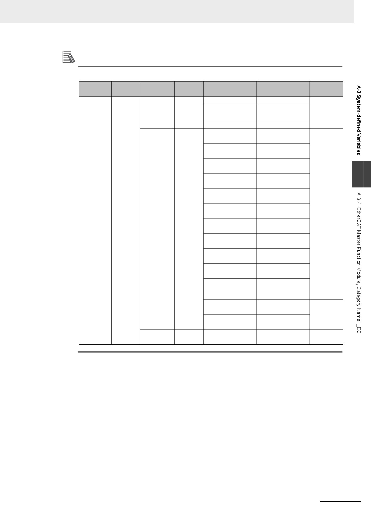
Appendices
Additional Information
Typical Relationships for the Built-in EtherCAT Error Flags
Variable
Variable
Meaning
Meaning
Variable Name
Meaning
Event level
Name
Name
_EC_ErrSta
Built-in
_EC_PortErr
Communi-
_EC_MacAdrErr
MAC Address Error
Partial fault
EtherCAT
cations
level
_EC_LanHwErr
Communications
Error
Port Error
Controller Error
_EC_LinkOffErr
Link OFF Error
_EC_MstrErr
Master
_EC_NetCfgErr
Network Configura-
Minor fault
Error
tion Information Error
level
_EC_NetCfgCmpErr
Network Configura-
tion Verification Error
_EC_NetTopologyErr
Network Configura-
tion Error
A
_EC_PDCommErr
Process Data Com-
munications Error
_EC_PDTimeoutErr
Process Data Recep-
tion Timeout Error
_EC_PDSendErr
Process Data Trans-
mission Error
_EC_SlavAdrDupErr
Slave Node Address
Duplicated Error
_EC_SlavInitErr
Slave Initialization
Error
_EC_SlavAppErr
Slave Application
Error
_EC_CommErrTbl
Communications
Error Slave Table
_EC_CycleExceeded
EtherCAT Communi-
cations Cycle
Exceeded
_EC_MsgErr
EtherCAT Message
Observation
Error
_EC_SlavEmergErr
Emergency Message
Detected
_EC_SlavErr
Slave
_EC_SlavErrTbl
Slave Error Table
Defined by
Error
the slave.
Note
The values of all system-defined variables that are related to errors in EtherCAT communications do not
change until the cause of the error is removed and then the error in the Controller is reset with the trouble-
shooting functions of the Sysmac Studio or the ResetECError instruction.
A-37

Appendices
z Functional Classification: EtherCAT Communications Status
Range of
Variable name
Meaning
Function
Data type
Reference
values
_EC_RegSlavTbl
Registered Slave
This table indicates the slaves that are
Array [1..512]
TRUE or
page A-75
Table
registered in the network configuration
OF BOOL
FALSE
information. Slaves are given in the table
in the order of slave node addresses. The
element for a slave is TRUE if the corre-
sponding slave is registered.
_EC_EntrySlavTbl
Network
This table indicates which slaves are con-
Array [1..512]
TRUE or
page A-75
Connected Slave
nected to the network. Slaves are given in
OF BOOL
FALSE
Table
the table in the order of slave node
addresses. The element for a slave is
TRUE if the corresponding slave has
entered the network.
_EC_MBXSlavTbl
Message Communi-
This table indicates the slaves that can
Array [1..512]
TRUE or
page A-75
cations Enabled
perform message communications.
OF BOOL
FALSE
Slave Table
Slaves are given in the table in the order
of slave node addresses.
The element for a slave is TRUE if mes-
sage communications are enabled for it
(pre-operational, safe-operation, or opera-
tional state).
Note Use this variable to confirm that
message communications are pos-
sible for the relevant slave before
you execute message communica-
tions with an EtherCAT slave.
_EC_PDSlavTbl
Process Data Com-
This table indicates the slaves that are
Array [1..512]
TRUE or
page A-76
municating Slave
performing process data communications.
OF BOOL
FALSE
Table
Slaves are given in the table in the order
of slave node addresses.
The element for a slave is TRUE if pro-
cess data of the corresponding slave is
enabled (operational) for both slave inputs
and outputs.
Note Use this variable to confirm that the
data for the relevant slave is valid
before controlling an EtherCAT
slave.
_EC_DisconnSlavTbl
Disconnected Slave
Slaves are given in the table in the order
Array [1..512]
TRUE or
page A-76
Table
of slave node addresses.
OF BOOL
FALSE
The element for a slave is TRUE if the
corresponding slave was disconnected.
_EC_DisableSlavTbl
Disabled Slave Table
Slaves are given in the table in the order
Array [1..512]
TRUE or
page A-76
of slave node addresses.
OF BOOL
FALSE
The element for a slave is TRUE if the
corresponding slave is disabled.
_EC_PDActive
Process Data Com-
TRUE when process data communica-
BOOL
TRUE or
page A-76
munications Status
tions are performed with all slaves*.
FALSE
* Disabled slaves are not included.
_EC_PktMonStop
Packet
TRUE when packet monitoring is stopped.
BOOL
TRUE or
page A-77
Monitoring Stopped
FALSE
_EC_LinkStatus
Link Status
TRUE if the communications controller
BOOL
TRUE or
page A-77
link status is Link ON.
FALSE
_EC_PktSaving
Saving Packet Data
Shows whether a packet data file is being
BOOL
TRUE or
page A-77
File
saved.
FALSE
TRUE: Packet data file being saved.
FALSE: Packet data file not being saved.
_EC_InDataInvalid
Input Data Invalid
TRUE when process data communica-
BOOL
TRUE or
page A-77
tions performed in the primary periodic
FALSE
task are not normal and the input data is
not valid.
A-38
Appendices
Range of
Variable name
Meaning
Function
Data type
Reference
values
_EC_InData1Invalid
Input Data1 Invalid
TRUE when process data communica-
BOOL
TRUE or
page A-77
tions performed in the primary periodic
FALSE
task are not normal and the input data is
not valid.
Note All system-defined variables that are related to the status of EtherCAT communications give the current status.
z Functional Classification: EtherCAT Communications Diagnosis/Statistics
Log
Range of
Variable name
Meaning
Function
Data type
Reference
values
_EC_StatisticsLogEn-
Diagnosis/Statistics
Changes to TRUE when the diagno-
BOOL
TRUE or
page A-78
able
Log Enable
sis/statistics log is started.
FALSE
Changes to FALSE when the diagno-
sis/statistics log is ended.
A
_EC_StatisticsLogCy-
Diagnosis/Statistics
Specifies the interval to write the diagnos-
UINT
0, or 30 to
page A-78
cleSec
Log Cycle
tic and statistical information of the diag-
1800
nosis/statistics log in units of seconds.
When 0 is specified, the diagnostic and
statistical information is written only once
when the diagnosis/statistics log is ended.
Note The write interval does not change
even if you change the value of this
system-defined variable while the
diagnosis/statistics log operation is
in progress.
_EC_StatisticsLog-
Diagnosis/Statistics
TRUE while the diagnosis/statistics log
BOOL
TRUE or
page A-78
Busy
Log Busy
operation is in progress.
FALSE
_EC_StatisticsLogErr
Diagnosis/Statistics
TRUE when the diagnosis/statistics log
BOOL
TRUE or
page A-78
Log Error
failed to start or it is impossible to write
FALSE
into the log.
The value of this flag is determined when
_EC_StatisticsLogBusy (Diagnosis/Statis-
tics Log Busy) changes to FALSE after the
diagnosis/statistics log operation is
started.
The error end is caused by the following.
• Another records cannot be added in the
log file because the capacity of the Vir-
tual SD Memory Card is fully used.
• There is no Virtual SD Memory Card.
• The function cannot be started because
the value specified for _EC_Statis-
ticsLogCycleSec (Diagnosis/Statistics
Log Cycle) is invalid.
A-39

Appendices
A-3-5
EtherNet/IP Function Module, Category Name: _EIP
z Functional Classification: EtherNet/IP Communications Errors
Range of
Variable name
Meaning
Function
Data type
Reference
values
_EIP_ErrSta
Built-in
This is the error status variable for the
WORD
16#0000 to
page A-79
EtherNet/IP Error
built-in EtherNet/IP port.
16#00F0
NY-series Controllers: Represents the col-
lective status of the following error flags.
•
_EIP1_PortErr (Communications Port1
Error)
•
_EIPIn1_PortErr (Internal Port1 Error)
•
_EIP_CipErr (CIP Communications
Error)
•
_EIP_TcpAppErr (TCP Application
Communications Error)
Note Refer to information on the mean-
ings of the error status bits at the
end of this appendix for details.
_EIP_PortErr
Communications Port
This is the error status variable for the
WORD
16#0000 to
page A-79
Error
communications port.
16#00F0
NY-series Controllers: Represents the col-
lective status of the following error flags.
•
_EIP1_MacAdrErr (Port1 MAC Address
Error)
•
_EIP1_LanHwErr (Port1 Communications
Controller Error)
•
_EIP1_EtnCfgErr (Port1 Basic Ethernet Set-
ting Error)
•
_EIP1_IPAdrCfgErr (Port1 IP Address Set-
ting Error)
•
_EIP1_IPAdrDupErr (Port1 IP Address
Duplication Error)
•
_EIP1_BootpErr (Port1 BOOTP Server
Error)
•
_EIP_DNSCfgErr (DNS Setting Error)
•
_EIP_DNSSrvErr (DNS Server Connec-
tion Error)
•
_EIP_IPRTblErr (IP Route Table Error)
Note If a Link OFF Detected or Built-in
EtherNet/IP
Processing
Error
occurs, it is recorded in the event
log and then the corresponding bit
turns ON. Refer to information on
the meanings of the error status bits
at the end of this appendix for
details.
A-40
Appendices
Range of
Variable name
Meaning
Function
Data type
Reference
values
_EIP1_PortErr
Communications
This is the error status variable for the
WORD
16#0000 to
page A-79
Port1 Error
communications port.
16#00F0
It represents the collective status of the
following error flags.
•
_EIP1_MacAdrErr (Port1 MAC Address
Error)
•
_EIP1_LanHwErr (Port1 Communications
Controller Error)
•
_EIP1_EtnCfgErr (Port1 Basic Ethernet Set-
ting Error)
•
_EIP1_IPAdrCfgErr (Port1 IP Address Set-
ting Error)
•
_EIP1_IPAdrDupErr (Port1 IP Address
Duplication Error)
•
_EIP1_BootpErr (Port1 BOOTP Server
Error)
A
•
_EIP_DNSCfgErr (DNS Setting Error)
•
_EIP_DNSSrvErr (DNS Server Connection
Error)
•
_EIP_IPRTblErr (IP Route Table Error)
Note If a Link OFF Detected or Built-in
EtherNet/IP
Processing
Error
occurs, it is recorded in the event
log and then the corresponding bit
turns ON.
Refer to information on the mean-
ings of the error status bits at the
end of this appendix for details.
_EIPIn1_PortErr
Internal Port1 Error
This is the error status variable for the
WORD
16#0000 to
page A-80
internal port 1.
16#00F0
It represents the collective status of the
following error flags.
•
_EIPIn1_IPAdrCfgErr (Internal Port1 IP
Address Setting Error)
•
_EIP1_IPAdrDupErr (Internal Port1 IP
Address Duplication Error)
•
_EIP_DNSCfgErr (DNS Setting Error)
•
_EIP_DNSSrvErr (DNS Server Connec-
tion Error)
•
_EIP_IPRTblErr (IP Route Table Error)
Note If a Link OFF Detected or Built-in
EtherNet/IP
Processing
Error
occurs, it is recorded in the event
log and then the corresponding bit
turns ON.
Refer to information on the mean-
ings of the error status bits at the
end of this appendix for details.
A-41

Appendices
Range of
Variable name
Meaning
Function
Data type
Reference
values
_EIP_CipErr
CIP Communications
This is the error status variable for CIP
WORD
16#0000 to
page A-80
Error
communications.
16#00F0
NY-series Controller: Represents the col-
lective status of the following error flags.
•
_EIP_IdentityErr (Identity Error)
•
_EIP_TDLinkCfgErr (Tag Data Link Set-
ting Error)
•
_EIP_TDLinkOpnErr (Tag Data Link
Connection Failed)
•
_EIP_TDLinkErr (Tag Data Link Com-
munications Error)
•
_EIP_TagAdrErr (Tag Name Resolution
Error)
•
_EIP_MultiSwONErr (Multiple Switches
ON Error)
Note If a Tag Name Resolution Error
occurs, it is recorded in the event
log and this variable changes to
TRUE. Refer to information on the
meanings of the error status bits at
the end of this appendix for details.
_EIP_TcpAppErr
TCP Application
This is the error status variable for TCP appli-
WORD
16#0000 to
page A-81
Communications
cation communications.
16#00F0
Error
It represents the collective status of the
following error flags.
•
_EIP_TcpAppCfgErr (TCP Application
Setting Error)
•
_EIP_NTPSrvErr (NTP Server Connection
Error)
Note Refer to information on the mean-
ings of the error status bits at the
end of this appendix for details.
_EIP_MacAdrErr
MAC Address Error
NY-series Controller: Indicates that an
BOOL
TRUE or
page A-81
error occurred when the MAC address
FALSE
was read on the communications port 1 at
startup.
TRUE: Error
FALSE: Normal
_EIP1_MacAdrErr
Port1 MAC Address
Indicates that an error occurred when the
BOOL
TRUE or
page A-81
Error
MAC address was read on the communi-
FALSE
cations port 1 at startup.
TRUE: Error
FALSE: Normal
_EIP_LanHwErr
Communications Con-
NY-series Controller: Indicates that a com-
BOOL
TRUE or
page A-81
troller Error
munications controller failure occurred on
FALSE
the communications port 1.
TRUE: Failure
FALSE: Normal
_EIP1_LanHwErr
Port1 Communica-
Indicates that a communications controller
BOOL
TRUE or
page A-82
tions Controller Error
failure occurred on the communications
FALSE
port 1.
TRUE: Failure
FALSE: Normal
_EIP_EtnCfgErr
Basic Ethernet Setting
NY-series Controller: Indicates that the
BOOL
TRUE or
page A-82
Error
Ethernet communications speed setting
FALSE
(Speed/Duplex) for the communications
port 1 is incorrect. Or, a read operation
failed.
TRUE: Setting incorrect or read failed
FALSE: Normal
A-42
Appendices
Range of
Variable name
Meaning
Function
Data type
Reference
values
_EIP1_EtnCfgErr
Port1 Basic Ethernet
Indicates that the Ethernet communica-
BOOL
TRUE or
page A-82
Setting Error
tions speed setting (Speed/Duplex) for the
FALSE
communications port 1 is incorrect. Or, a
read operation failed.
TRUE: Setting incorrect or read failed
FALSE: Normal
_EIP_IPAdrCfgErr
IP Address Setting
NY-series Controller: Indicates the IP
BOOL
TRUE or
page A-82
Error
address setting errors for the communica-
FALSE
tions port 1.
TRUE:
• There is an illegal IP address
setting.
• A read operation failed.
• The IP address obtained from
the BOOTP server is incon-
sistent.
A
FALSE: Normal
_EIP1_IPAdrCfgErr
Port1 IP Address Set-
Indicates the IP address setting errors for
BOOL
TRUE or
page A-83
ting Error
the communications port 1.
FALSE
TRUE:
• There is an illegal IP address
setting.
• A read operation failed.
• The IP address obtained from
the BOOTP server is incon-
sistent.
FALSE: Normal
_EIPIn1_IPAdrCfgErr
Internal Port1 IP
Indicates the IP address setting errors for
BOOL
TRUE or
page A-83
Address Setting Error
the internal port 1.
FALSE
TRUE:
• There is an illegal IP address
setting.
• A read operation failed.
• The IP address obtained from
the BOOTP server is incon-
sistent.
FALSE: Normal
_EIP_IPAdrDupErr
IP Address Duplica-
NY-series Controller: Indicates that the
BOOL
TRUE or
page A-83
tion Error
same IP address is assigned to more than
FALSE
one node for the communications port 1.
TRUE: Duplication occurred.
FALSE: Other than the above.
_EIP1_IPAdrDupErr
Port1 IP Address
Indicates that the same IP address is
BOOL
TRUE or
page A-83
Duplication Error
assigned to more than one node for the
FALSE
communications port 1.
TRUE: Duplication occurred.
FALSE: Other than the above.
_EIPIn1_IPAdrDupErr
Internal Port1 IP
Indicates that the same IP address is
BOOL
TRUE or
page A-83
Address Duplication
assigned to more than one node for the
FALSE
Error
internal port 1.
TRUE: Duplication occurred.
FALSE: Other than the above.
_EIP_DNSCfgErr
DNS Setting Error
Indicates that the DNS or hosts settings
BOOL
TRUE or
page A-84
are incorrect. Or, a read operation failed.
FALSE
TRUE: Setting incorrect or read failed
FALSE: Normal
A-43

Appendices
Range of
Variable name
Meaning
Function
Data type
Reference
values
_EIP_BootpErr
BOOTP Server Error
NY-series Controller: Indicates that a
BOOL
TRUE or
page A-84
BOOTP server connection failure
FALSE
occurred on the communications port 1.
TRUE: There was a failure to connect to
the BOOTP server (timeout).
FALSE: The BOOTP is not enabled, or
BOOTP is enabled and an IP
address was normally obtained
from the BOOTP server.
_EIP1_BootpErr
Port1 BOOTP Server
Indicates that a BOOTP server connection
BOOL
TRUE or
page A-84
Error
failure occurred on the communications
FALSE
port 1.
TRUE: There was a failure to connect to
the BOOTP server (timeout).
FALSE: The BOOTP is not enabled, or
BOOTP is enabled and an IP
address was normally obtained
from the BOOTP server.
_EIP_IPRTblErr
IP Route Table Error
NY-series Controller: Indicates that the
BOOL
TRUE or
page A-84
default gateway settings or IP router table
FALSE
settings are incorrect.
Or, a read operation failed.
TRUE: Setting incorrect or read failed
FALSE: Normal
_EIP_IdentityErr
Identity Error
NY-series Controller: Indicates that the
BOOL
TRUE or
page A-84
identity information for CIP communica-
FALSE
tions 1 (which you cannot overwrite) is
incorrect. Or, a read operation failed.
TRUE: Setting incorrect or read failed
FALSE: Normal
_EIP_TDLinkCfgErr
Tag Data Link Setting
NY-series Controller: Indicates that the tag
BOOL
TRUE or
page A-85
Error
data link settings for CIP communications
FALSE
1 are incorrect. Or, a read operation failed.
TRUE: Setting incorrect or read failed
FALSE: Normal
_EIP_TDLinkOpnErr
Tag Data Link Con-
NY-series Controller: Indicates that estab-
BOOL
TRUE or
page A-85
nection Failed
lishing a tag data link connection for CIP
FALSE
communications 1 failed.
TRUE: Establishing a tag data link con-
nection failed due to one of the
following causes.
• The information registered for
a target node in the tag data
link parameters is different
from the actual node informa-
tion.
• There was no response from
the remote node.
FALSE: Other than the above.
_EIP_TDLinkErr
Tag Data Link Com-
NY-series Controller: Indicates that a time-
BOOL
TRUE or
page A-85
munications Error
out occurred in a tag data link connection
FALSE
for CIP communications 1.
TRUE: A timeout occurred.
FALSE: Other than the above.
A-44
Appendices
Range of
Variable name
Meaning
Function
Data type
Reference
values
_EIP_TagAdrErr
Tag Name Resolution
NY-series Controller: Indicates that tag
BOOL
TRUE or
page A-85
Error
resolution for CIP communications 1 failed
FALSE
(i.e., the address could not be identified
from the tag name).
TRUE: Tag resolution failed (i.e., the
address could not be identified
from the tag name). The follow-
ing causes are possible.
• The size of the network vari-
able is different from the tag
settings.
• The I/O direction that is set in
the tag data link settings does
not agree with the I/O direc-
tion of the variable in the Con-
troller.
• There is no network variable
A
in the Controller that corre-
sponds to the tag setting.
FALSE: Other than the above.
_EIP_MultiSwONErr
Multiple Switches ON
NY-series Controller: Indicates that more
BOOL
TRUE or
page A-86
Error
than one switch turned ON at the same
FALSE
time in CIP communications 1.
TRUE: More than one data link start/stop
switch changed to TRUE at the
same time.
FALSE: Other than the above.
_EIP_TcpAppCfgErr
TCP Application
TRUE: At least one of the set values for a
BOOL
TRUE or
page A-86
Setting Error
TCP application (FTP, NTP,
FALSE
SNMP) is incorrect. Or, a read
operation failed.
FALSE: Normal
_EIP_NTPSrvErr
NTP Server Connec-
Always FALSE for an NY-series Control-
BOOL
TRUE or
page A-86
tion Error
ler.
FALSE
_EIP_DNSSrvErr
DNS Server Connec-
TRUE: The DNS client failed to connect to
BOOL
TRUE or
page A-86
tion Error
the server (timeout).
FALSE
FALSE: DNS is not enabled. Or, DNS is
enabled and the connection was
successful.
Hierarchical Relationship of System-defined Variables Related to EtherNet/IP Errors in the
NY-series Controller
The system-defined variables that are related to EtherNet/IP errors have the following hierarchical
relationship. For example, if the value of any of the _EIP1_PortErr, _EIPIn1_PortErr, _EIP_CipErr,
and _EIP_TcpAppErr variables in the second level is TRUE, then the _EIP_ErrSta variable in the
first level also changes to TRUE. Therefore, you can check the values of system-defined variables
in a higher level to see if an error has occurred for a variable in a lower level.
A-45
Appendices
Level 1
Level 2
Level 3
Variable
Name
Variable
Name
Variable
Name
_EIP_ErrSta
Built-in
_EIP1_Po
Communi-
_EIP1_MacAdrErr
Port1 MAC Address Error
EtherNet/IP
rtErr
cations
_EIP1_LanHwErr
Port1 Communications Controller
Error
Port1
Error
Error
_EIP1_EtnCfgErr
Port1 Basic Ethernet Setting Error
_EIP1_IPAdrCfgErr
Port1 IP Address Setting Error
_EIP1_IPAdrDupErr
Port1 IP Address Duplication Error
_EIP1_BootpErr
Port1 BOOTP Server Error
_EIP_DNSCfgErr
DNS Setting Error
_EIP_DNSSrvErr
DNS Server Connection Error
_EIP_IPRTblErr
IP Route Table Error
_EIPIn1_
Internal
_EIPIn1_IPAdrCfgErr
Internal Port1 IP Address Setting
PortErr
Port1
Error
Error
_EIPIn1_IPAdrDupErr
Internal Port1 IP Address Duplication
Error
_EIP_DNSCfgErr
DNS Setting Error
_EIP_DNSSrvErr
DNS Server Connection Error
_EIP_IPRTblErr
IP Route Table Error
_EIP_Ci-
CIP Com-
_EIP_IdentityErr
Identity Error
pErr
munica-
_EIP_TDLinkCfgErr
Tag Data Link Setting Error
tions Error
_EIP_TDLinkOpnErr
Tag Data Link Connection Failed
_EIP_TDLinkErr
Tag Data Link Communications Error
_ EIP_TagAdrErr
Tag Name Resolution Error
_EIP_MultiSwONErr
Multiple Switches ON Error
_EIP_Tc-
TCP
_EIP_TcpAppCfgErr
(TCP Application Setting Error)
pAppErr
Applica-
_EIP_NTPSrvErr
NTP Server Connection Error
tion Com-
municatio
ns Error
Note
You can access the same values of the system-defined variables whose variable names with _EIP1 and the
system-defined variables whose variable names with _EIP. For example, you can access the same values of
_EIP1_PortErr (Communications Port1 Error) and _EIP_PortErr (Communcations Port Error).
A-46
Appendices
z Functional Classification: EtherNet/IP Communications Status
Range of
Variable name
Meaning
Function
Data type
Reference
values
_EIP_EtnOnlineSta
Online
NY-series Controller: Indicates that the
BOOL
TRUE or
page A-86
built-in EtherNet/IP port’s communications
FALSE
can be used via the communications port
1 (that is, the link is ON, IP address is
defined, and there are no errors).
TRUE: The built-in EtherNet/IP port’s
communications can be used.
FALSE: The built-in EtherNet/IP port’s
communications is disabled due
to an error in initial processing,
restart processing, or link OFF
status.
_EIP1_EtnOnlineSta
Port1 Online
Indicates that the built-in EtherNet/IP
BOOL
TRUE or
page A-87
port’s communications can be used via
FALSE
the communications port 1 (that is, the link
A
is ON, IP address is defined, and there
are no errors).
TRUE: The built-in EtherNet/IP port’s
communications can be used.
FALSE: The built-in EtherNet/IP port’s
communications is disabled due
to an error in initial processing,
restart processing, or link OFF
status.
_EIPIn1_EtnOnlin-
Internal Port1 Online
Indicates that the built-in EtherNet/IP
BOOL
TRUE or
page A-87
eSta
port’s communications can be used via
FALSE
the internal port 1 (that is, the link is ON,
IP address is defined, and there are no
errors.)
TRUE: The built-in EtherNet/IP port’s
communications can be used.
FALSE: The built-in EtherNet/IP port’s
communications is disabled due
to an error in initial processing,
restart processing, or link OFF
status.
_EIP_TDLinkRunSta
Tag Data Link Com-
NY-series Controller: Indicates that at
BOOL
TRUE or
page A-87
munications Status
least one connection is in normal opera-
FALSE
tion in CIP communications 1.
TRUE: Normal operation
FALSE: Other than the above.
_EIP_TDLinkAllRun-
All Tag Data Link
NY-series Controller: Indicates that all tag
BOOL
TRUE or
page A-87
Sta
Communications Sta-
data links are communicating in CIP com-
FALSE
tus
munications 1.
TRUE: Tag data links are communicating
in all connections as the origina-
tor.
FALSE: An error occurred in at least one
connection.
_EIP_RegTargetSta
Registered Target
NY-series Controller: Gives a list of nodes
ARRAY
TRUE or
page A-88
[255]
Node Information
for which built-in EtherNet/IP connections
[0..255] OF
FALSE
are registered for CIP communications 1.
BOOL
This variable is valid only when the built-in
EtherNet/IP port is the originator.
Array[x] is TRUE:
The connection to the node with a tar-
get node ID of x is registered.
Array[x] is FALSE:
The connection to the node with a tar-
get node ID of x is not registered.
A-47