Omron IPC Machine Controller Industrial Panel PC / Industrial Box PC. Software User’s Manual (Industrial PC Platform NY-series) - page 6
5 Designing Tasks
5-5
Assignment and Settings Related to
Tasks
This section describes the assignment and setting related to tasks.
5-5-1
Assigning I/O Refreshing to Tasks
I/O refreshing of the EtherCAT slaves is assigned to the tasks. Unit of assignment is different depend-
ing on the target for I/O refreshing. Unit of assignment refers to a target or a group of targets for I/O
refreshing assigned to one task. For example, when the unit of assignment is Slave Terminal, you can
assign I/O refreshing to only one task even if more than one NX Unit is connected to a Communications
Coupler Unit.
If you want to perform input and output operations in tasks to which I/O refreshing is not assigned, refer
to Input and Output Operations in Tasks to Which I/O Refreshing Is Not Assigned on page 5-34.
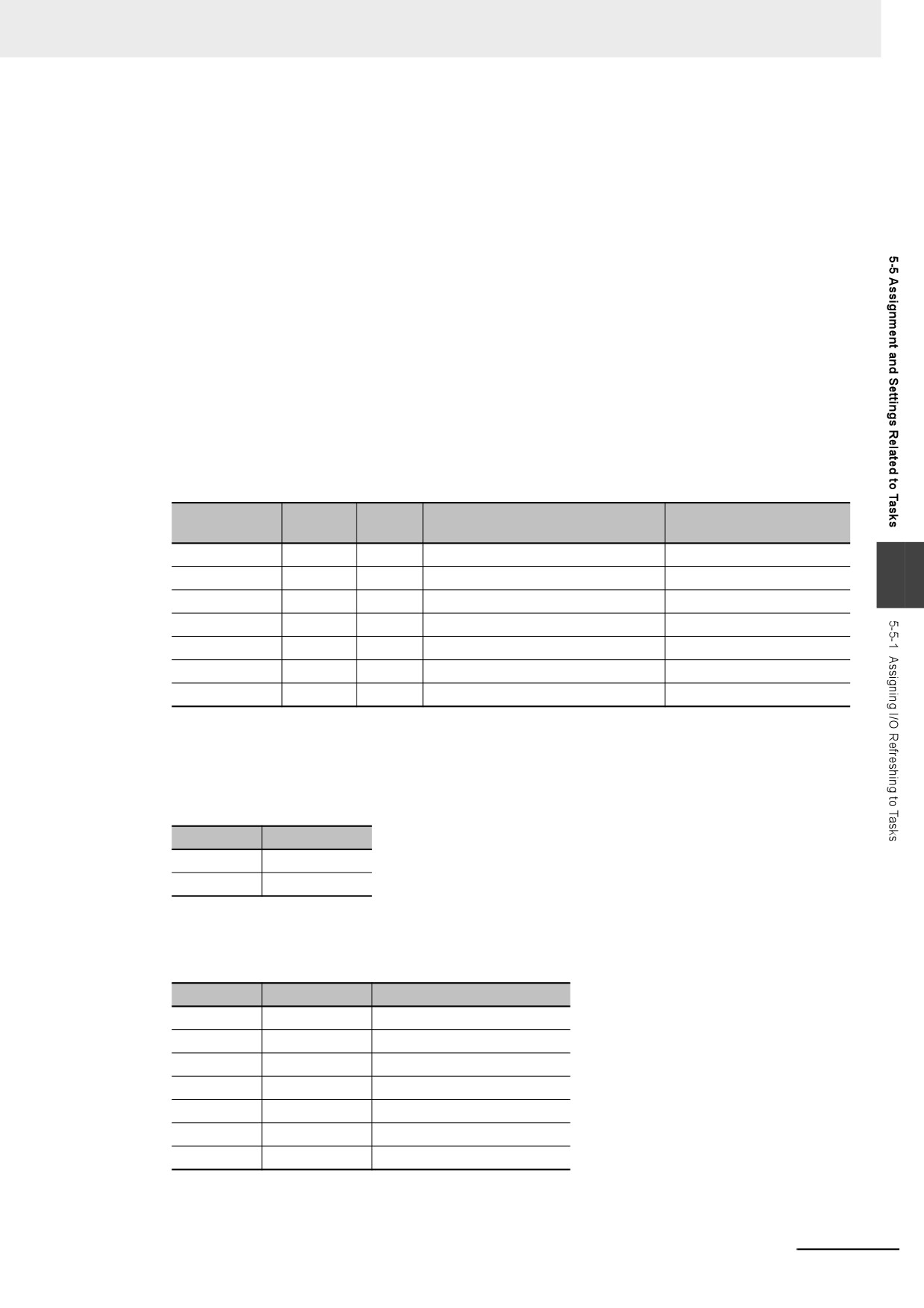
The following table shows the relationship among the target for I/O refreshing, the assignable task, and
the unit of assignment.
I/O refreshing target
Assignable task
Unit of assignment
Communications Coupler Unit
Primary periodic task
Slave Terminal
5
EtherCAT slaves
Primary periodic task
Slave
Sysmac Studio Setting Procedure
For the slaves and Units that are not assigned to axes, set the tasks in which to perform I/O refreshing
in I/O Control Task Settings under Configuration and Setup - Task Settings on the Sysmac Studio.
Refer to I/O Control Task Settings on page 4-9 for details.
For the slaves and Units that are assigned to axes, specify the motion controls to use in Motion Con-
trol Setup under Configurations and Setup on the Sysmac Studio. The tasks to perform I/O refresh-
ing are set.
Refer to the NY-series Industrial Panel PC / Industrial Box PC Motion Control User's Manual (Cat. No.
W559) for details.
Timing of I/O Refreshing
The table below shows when I/O is refreshed for EtherCAT slaves.
I/O refreshing target
I/O control task
Period of I/O refreshing
EtherCAT slaves
Primary periodic task
Task period of the primary periodic task
Accessing I/O from the User Program
You use device variables to access I/O ports from the user program.
Access the device variables from a program in the task that is set in the I/O Control Task Settings.
5-33
5 Designing Tasks
Input and Output Operations in Tasks to Which I/O Refreshing Is Not
Assigned
If you attempt to output data directly from a task to which I/O refreshing is not assigned, an error will
occur when you check the program on the Sysmac Studio. For example, if the processes for NX Units
are assigned to different tasks on the Slave Terminal, data can be output only from the task to which I/O
refreshing is assigned. In this case, you need to create the program to pass the data from the task to
which I/O refreshing is not assigned to the task to which I/O refreshing is assigned and output data from
the task to which I/O refreshing is assigned.
The following sample programming shows how to pass the data from the task to which I/O refreshing is
not assigned to the task to which I/O refreshing is assigned and output data from the task to which I/O
refreshing is assigned.
In this sample programming, the external data input processing is performed in a task to which I/O
refreshing is not assigned. Usually, this kind of processing causes a warning to occur when you check
the program on the Sysmac Studio. However, the execution of processing is possible.
z Unit Configuration
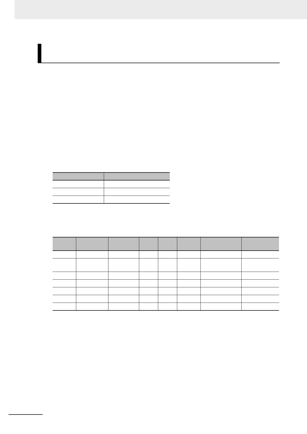
A Slave Terminal is used. The following table shows the Unit configuration of the Slave Terminal.
Model number
Product name
NX-ECC20
EtherCAT Coupler Unit
NX-ID3317
DC Input Unit
NX-OD3256
Transistor Output Unit
z I/O Map
The following I/O map is used. The table below shows the bits that are used in the sample program-
ming.
Data
Variable com-
Position
Port
Description
R/W
Variable
Variable type
type
ment
Unit1
NX-ID3317
Input Bit 00
Input bit 00
R
BOOL
ComIn
Common input
Global variable
value
Unit2
NX-OD3256
Output Bit 00
Output bit 00
W
BOOL
OutA1
Output value A1
Global variable
Output Bit 01
Output bit 01
W
BOOL
OutA2
Output value A2
Global variable
Output Bit 02
Output bit 02
W
BOOL
OutB1
Output value B1
Global variable
Output Bit 03
Output bit 03
W
BOOL
OutB2
Output value B2
Global variable
5-34
5 Designing Tasks
z
I/O Specifications
The I/O specifications are as follows:
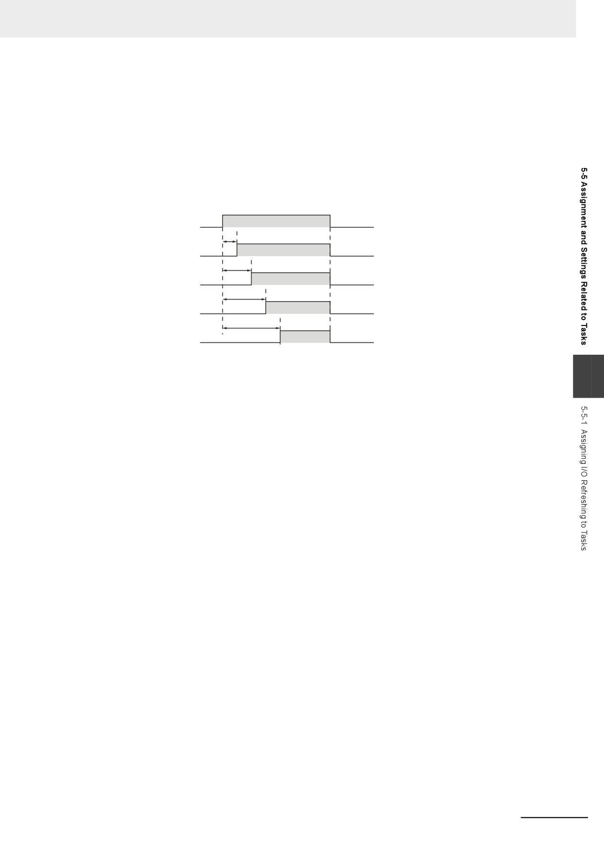
• OutA1 changes from FALSE to TRUE one second after the value of ComIn changes from FALSE
to TRUE. In the same way, OutA2 changes to TRUE two seconds, OutB1 three seconds and
OutB2 four seconds after the value of ComIn changes to TRUE.
• When the value of ComIn changes from TRUE to FALSE, the values of OutA1, OutA2, OutB1 and
OutB2 change from TRUE to FALSE.
The following figure shows the timing chart.
TRUE
ComIn
FALSE
1s
TRUE
OutA1
FALSE
2s
TRUE
OutA2
FALSE
3s
TRUE
OutB1
FALSE
4s
TRUE
OutB2
FALSE
z
Task Processing
5
The primary periodic task and priority-16 periodic task are used. The I/O refreshing is assigned to
the primary periodic task.
OutA1 and OutA2 are controlled in the primary periodic task. A series of processing, i.e., input of
ComIn, calculations and outputs of OutA1 and OutA2, is performed in the primary periodic task.
For controls of OutB1 and OutB2, the processing from input of ComIn to calculations is performed in
the periodic task. The calculation results of the periodic task are assigned to the temporary global
variables tmp_OutB1 and tmp_OutB2. In the primary periodic task, the values of tmp_OutB1 and
tmp_OutB2 are assigned to OutB1 and OutB2. Then, OutB1 and OutB2 are output.
The Controller may pause the periodic task in order to execute the primary periodic task. The
assignment of calculation results to tmp_OutB1 and tmp_OutB2 may be performed before or after
the pause of the periodic task. And the timing of assignment determines the timing of output of cal-
culation results in the primary periodic task.
5-35
5 Designing Tasks
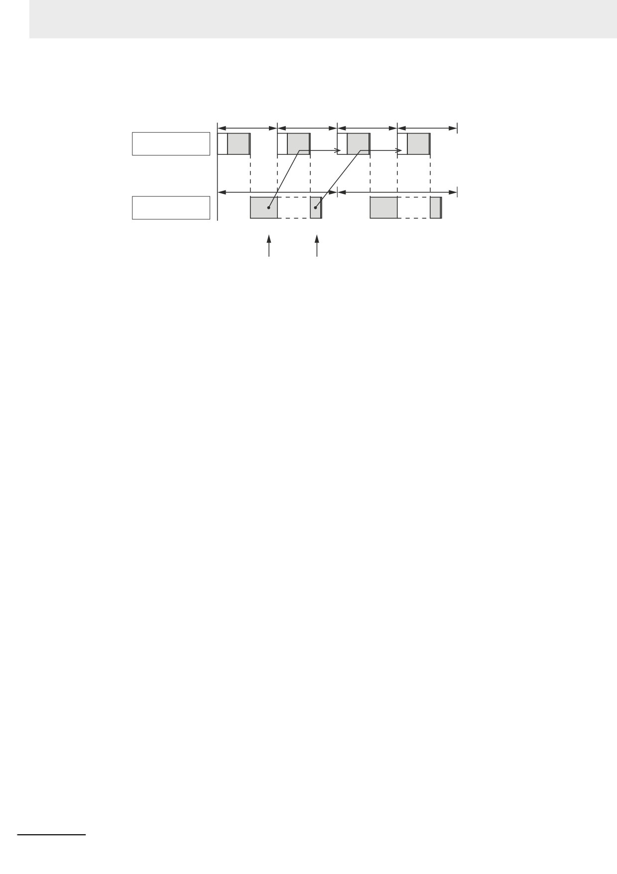
The following figure shows an example of processing flow. The task period of the periodic task is set
to twice as long as that of the primary periodic task.
Task period
Primary
IOUPG
IO
UPG
IO
UPG
IO
UPG
periodic task
(1)
(2)
(5)
(6)
(8)
(9)
(10)
Task period
Priority-16
Pausing
Pausing
periodic task
(3)
(4)
(7)
If the values are assigned to tmp_OutB1
If the values are assigned to tmp_OutB1
and tmp_OutB2 in step (4), they are
and tmp_OutB2 in step (7), they are
output in step (8).
output in step (10).
(1)
ComIn is input during I/O refreshing in the primary periodic task.
(2)
The calculation is performed during the user program execution in the primary peri-
odic task and the values are assigned to OutA1 and OutA2.
Also, the values of tmp_OutB1 and tmp_OutB2 are assigned to OutB1 and OutB2.
However, the values of tmp_OutB1 and tmp_OutB2 are the initial values because the
values are not assigned to tmp_OutB1 and tmp_OutB2 in the periodic task. There-
fore, the values of OutB1 and OutB2 are also the initial values.
(3)
ComIn is input in the periodic task.
(4)
The calculation is performed during the user program execution in the periodic task.
If the primary periodic task is executed while the periodic task execution is in prog-
ress, the periodic task is paused. Depending on the timing of processing in the peri-
odic task, the assignment of the values to tmp_OutB1 and tmp_OutB2 may be
performed before or after the pause of the periodic task.
(5)
OutA1, OutA2, OutB1 and OutB2 are output during I/O refreshing in the primary peri-
odic task.
Also, ComIn is input again.
(6)
The calculation is performed during the user program execution in the primary peri-
odic task and the values are assigned to OutA1 and OutA2.
Also, the values of tmp_OutB1 and tmp_OutB2 are assigned to OutB1 and OutB2. If
the values are assigned to tmp_OutB1 and tmp_OutB2 in step (4), the calculation
results of the periodic task are reflected in OutB1 and OutB2. If the values are not
assigned to tmp_OutB1 and tmp_OutB2 in step (4), the values of tmp_OutB1 and
tmp_OutB2 are the initial values. Therefore, the values of OutB1 and OutB2 are also
the initial values.
(7)
The calculation is performed during the user program execution in the periodic task
that follows step (4).
If the values are not assigned to tmp_OutB1 and tmp_OutB2 in step (4), they are
assigned here.
(8)
OutA1, OutA2, OutB1 and OutB2 are output during I/O refreshing in the primary peri-
odic task.
If the values are assigned to tmp_OutB1 and tmp_OutB2 in step (4), the calculation
results of the periodic task are output as OutB1 and OutB2.
If the values are assigned to tmp_OutB1 and tmp_OutB2 in step (7), the initial values
of OutB1 and OutB2 are output.
5-36
5 Designing Tasks
(9) The calculation is performed during the user program execution in the primary peri-
odic task and the values are assigned to OutA1 and OutA2.
Also, the values of tmp_OutB1 and tmp_OutB2 are assigned to OutB1 and OutB2. If
the values are assigned to tmp_OutB1 and tmp_OutB2 in step (7), the calculation
results of the periodic task are reflected in OutB1 and OutB2.
(10) OutA1, OutA2, OutB1 and OutB2 are output during I/O refreshing in the primary peri-
odic task.
If the values are assigned to tmp_OutB1 and tmp_OutB2 in step (7), the calculation
results of the periodic task are output as OutB1 and OutB2.
You can use the Lock and Unlock instructions to perform the task exclusive controls to prevent the
values of tmp_OutB1 and tmp_OutB2 from being overwritten by the periodic task before they are
accessed by the primary periodic task. Refer to 5-6-1 Ensuring Concurrency of Variable Values
between Tasks for details on task exclusive controls.
z
Global Variable Table
The global variables are shown below.
Global variable table
Initial
Name
Data type
AT specification
Comment
value
ComIn
BOOL
FALSE
ECAT://node#[1,1]/Input Bit 00
Common input value
OutA1
BOOL
FALSE
ECAT://node#[1,2]/Output Bit 00
Output value A1
5
OutA2
BOOL
FALSE
ECAT://node#[1,2]/Output Bit 01
Output value A2
OutB1
BOOL
FALSE
ECAT://node#[1,2]/Output Bit 02
Output value B1
OutB2
BOOL
FALSE
ECAT://node#[1,2]/Output Bit 03
Output value B2
tmp_OutB1
BOOL
FALSE
Temporary variable for B1
tmp_OutB2
BOOL
FALSE
Temporary variable for B2
z
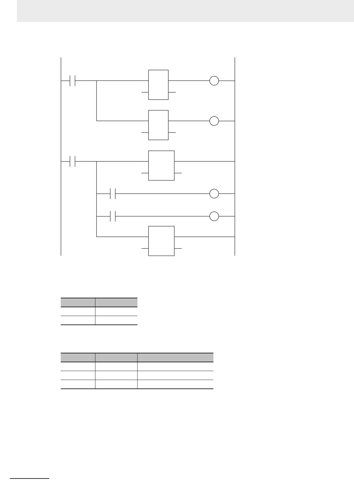
Ladder Diagram for Primary Periodic Task
The ladder diagram for the primary periodic task is shown below.
Internal variable table
Name
Data type
A1_Wait
TON
A2_Wait
TON
External variable table
Name
Data type
Comment
ComIn
BOOL
Common input value
OutA1
BOOL
Output value A1
OutA2
BOOL
Output value A2
OutB1
BOOL
Output value B1
OutB2
BOOL
Output value B2
tmp_OutB1
BOOL
Temporary variable for B1
tmp_OutB2
BOOL
Temporary variable for B2
5-37
5 Designing Tasks
Algorithm
Input of ComIn, calculations and outputs and output of OutA1 and OutA2
A1_Wait
ComIn
OutA1
TON
In
Q
T#1s
PT ET
A2_Wait
OutA2
TON
In
Q
T#2s
PT ET
Assignment of the values tmp_OutB1 and tmp_OutB2 to OutB1 and OutB2, and output of OutB1 and OutB2
P_On
Lock
En ENO
USINT#1
Index
tmp_OutB1
OutB1
tmp_OutB2
OutB2
Unlock
En ENO
USINT#1
Index
z
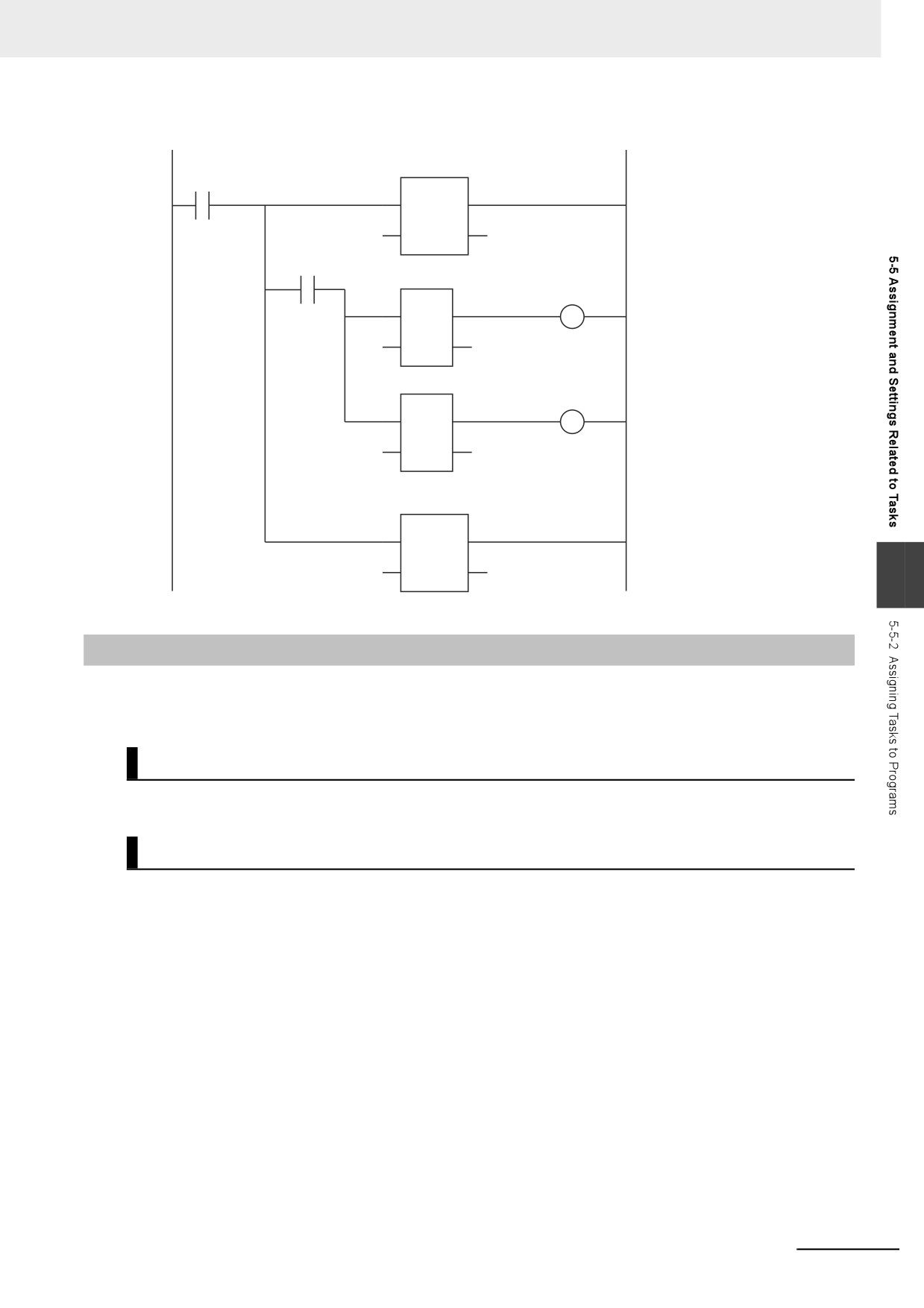
Ladder Diagram for Periodic Task
The ladder diagram for the periodic task is shown below.
Internal variable table
Name
Data type
B1_Wait
TON
B2_Wait
TON
External variable table
Name
Data type
Comment
ComIn
BOOL
Common input value
tmp_OutB1
BOOL
Temporary variable for B1
tmp_OutB2
BOOL
Temporary variable for B2
5-38
5 Designing Tasks
Algorithm for periodic task
Input of ComIn and calculations of tmp_OutB1 and tmp_OutB2
P_On
Lock
En ENO
USINT#1
Index
ComIn
B1_Wait
TON
tmp_OutB1
In
Q
T#3s
PT ET
B2_Wait
TON
tmp_OutB2
In
Q
T#4s
PT ET
Unlock
En ENO
USINT#1
Index
5
5-5-2
Assigning Tasks to Programs
You assign the programs to execute to tasks. (You can assign up to 128 programs to one task.) Also,
you set the operation of the programs at the start of operation.
Order of Program Execution
The order of execution of the programs in a task is set with the Sysmac Studio.
Initial Status for Programs at the Start of Operation
Set the operation of the programs at the start of operation. The Initial Status at the start of operation is
used to set whether to execute the program when the task to which the program is assigned is exe-
cuted for the first time after the operating mode of the Controller is changed from PROGRAM mode to
RUN mode. You have a setting option between Run or Stop.
If the Initial Status is Stop, when enabling the execution of the specified program with the PrgStart
instruction, it is executed from the next time the timing for executing the program occurs. If the Initial
Status is Run, when disabling the execution of the specified program with the PrgStop instruction, it is
disabled from the next time the timing for executing the program occurs.
z Sysmac Studio Setting Procedure
Assign programs to tasks, set the order of program execution within the task, and set the Initial Sta-
tus for each program in Program Assignment Settings under Configurations and Setup - Task
Settings on the Sysmac Studio. Refer to Program Assignment Settings on page 4-9 for details.
5-39
5 Designing Tasks
POUs That You Can Assign to Tasks
From 0 to 128 programs can be assigned to one task.
You can assign only program POUs. You cannot assign function block instances or functions directly to
tasks. You cannot assign the same program to more than one task.
5-5-3
Parameters for Primary Periodic Task and Periodic Tasks
The parameters for primary periodic task and periodic tasks are given below.
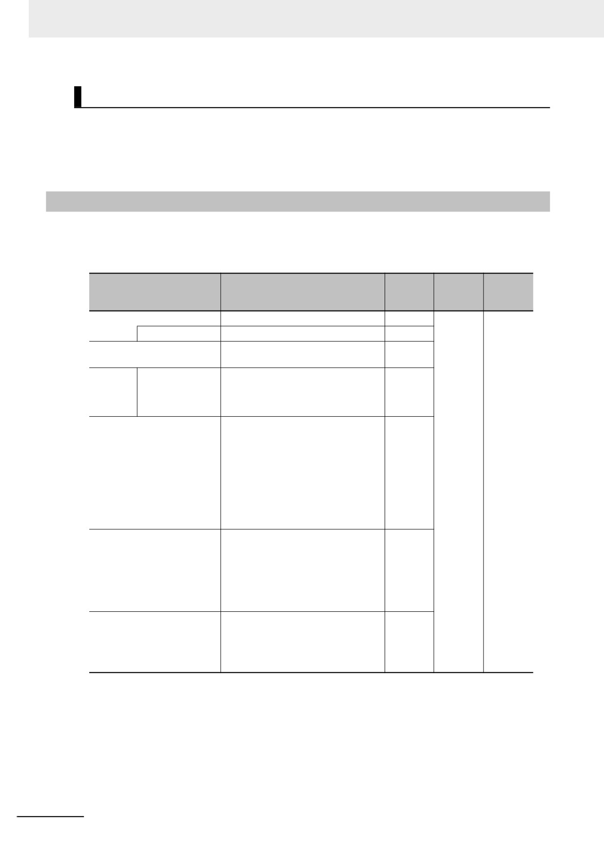
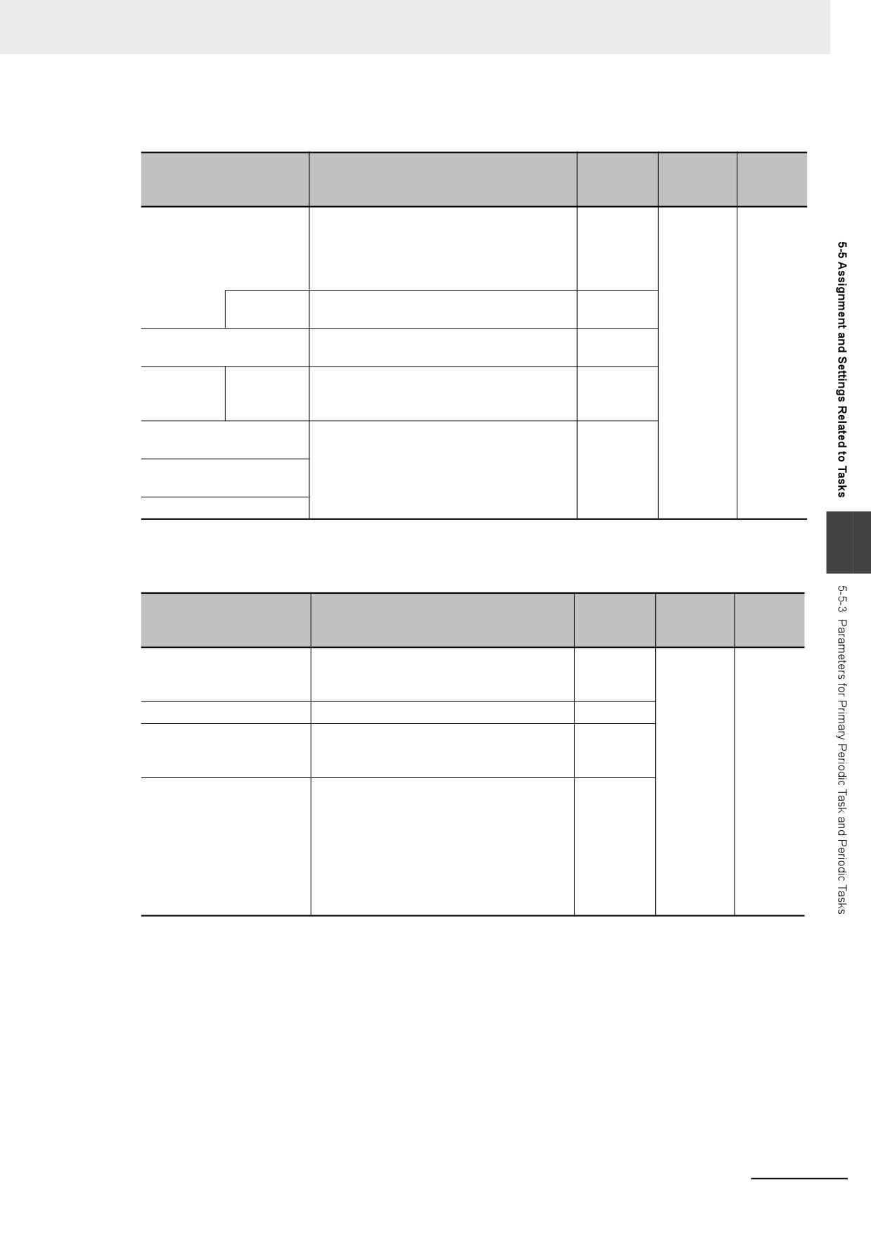
z Parameters for Primary Periodic Tasks
Changes
Update
Parameter
Setting range
Default
in RUN
timing
mode
Task Type
Specify the primary periodic task.
---
When
Not
down-
allowed.
Execution priority
Always 4.
---
loaded to
Task Name
Text string
Primary-
Controller
Task
Period/
Task period*1
500 μs to 8 ms (in 250-μs increments)
1 ms
Execu-
tion Con-
ditions
Task Period Exceeded Detec-
Specify whether to detect an error if
Detect.
tion
the task execution time exceeds the
specified task period.
• Detect (a minor fault level Controller
error occurred).
• Do not detect (an observation is
recorded in event log).
Refer to Task Period Exceeded on
page 5-53 for details.
Task Timeout Detection Time
Set the time to detect a timeout if task
5
execution does not end, e.g., if there is
an infinite loop.
Set a multiple of the task period.
1 to 5
Refer to Task Execution Timeout on
page 5-54 for details.
Variable Access Time [%]
Set the percentage of the task period
3%
to assign to variable access.
1% to 50%
Refer to Settings for Variable Access
Time on page 5-51 for details.
*1
The process data communications cycle (process data communications cycle) in the EtherCAT settings will
be the same as this period.
5-40
5 Designing Tasks
z Parameters for Priority-16, Priority-17, and Priority-18 Periodic Tasks
Changes
Update
Parameter
Setting range
Default
in RUN
timing
mode
Task Type
You can set any of the following.
---
When
Not
down-
allowed.
Priority-16 periodic task
loaded to
Priority-17 periodic task
Controller
Priority-18 periodic task
Execution
Automatically set to 16, 17, or 18.
---
priority
Task Name
Text string
Periodic
Task0
Period/
Task period
Refer to 5-3-1 Specifications of Tasks for
10 ms
Execution
NY-series Controllers.
Conditions
Task Period Exceeded
The same as for the primary periodic task.
The same
Detection
as for the
primary
Task Timeout Detection
periodic
Time
task.
Variable Access Time [%]
5
z Event Task Parameters
Changes
Update
Parameter
Setting range
Default
in RUN
timing
mode
Task Type
You can set any of the following.
---
When
Not
Priority-8 event task
down-
allowed.
Priority-48 event task
loaded to
Controller
Task Name
Text string
EventTask0
Execution Condition
Select either Execution by instruction or
Execution
When a variable expression is satisfied.
with an
instruction
Task Timeout Detection
Set the time to detect a timeout if task exe-
• Execu-
Time
cution does not end, e.g., if there is an
tion prior-
infinite loop. The setting unit is millisec-
ity of 8:
onds.
200 ms
• Execution priority of 8: 1 to 500 ms
• Execu-
tion prior-
• Execution priority of 48: 1 ms to 10 s
ity of 48:
1 s
z Sysmac Studio Setting Procedure
Add and set the tasks in the Task Settings under Configurations and Setup on the Sysmac Stu-
dio.
Refer to Task Settings on page 4-7 for details.
5-41
5 Designing Tasks
5-6
Ensuring Concurrency of Variable
Values
This section describes how to ensure concurrency of variable values between tasks and provides an
overview of variable access from outside the Controller.
5-6-1
Ensuring Concurrency of Variable Values between Tasks
If more than one task reads or writes the same global variable, you can use either of the following two
methods to ensure the concurrency of the value of the global variable between the tasks. These are
collectively called the exclusive control of variables in tasks.
Method 1: Write the global variable from only one task and read the variable from the other tasks.
Use the settings for exclusive control of variables in tasks.
Method 2: Write the global variable from more than one task.
Use the task exclusive control instructions.
Method 1: Settings for Exclusive Control of Variables in Tasks
z
Introduction
You can specify the task that refreshes a global variable and the tasks that access the global vari-
able. This ensures the concurrency of the value of the global variable from the point of view of the
tasks that access the variable.
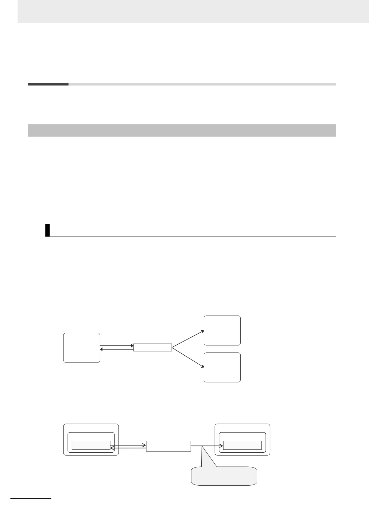
A single task is set to read and write the value of a specified global variable. That task is called the
refreshing task. Tasks that only read the value of the global variable are also specified. These tasks
are called accessing tasks. This ensures the concurrency of the value of the global variable.
Accessing
Read only
task: Task B
Read/write
Refreshing
Global variable
task: Task A
Refreshing task is specified.
Refreshing task: Task A
Accessing
Read only
task: Task C
z
Application Example
The refreshing task specification is used to ensure the concurrency of the value of a global variable
within a periodic task when the variable is written in the primary periodic task.
Refreshing task
Accessing task
Program
Program
Read/write
Read only
External variable GVar1
Global variable GVar1
External variable GVar1
The most recent value of the
variable at the end of refreshing
task execution is read at the start
of accessing task execution.
5-42
5 Designing Tasks
z System
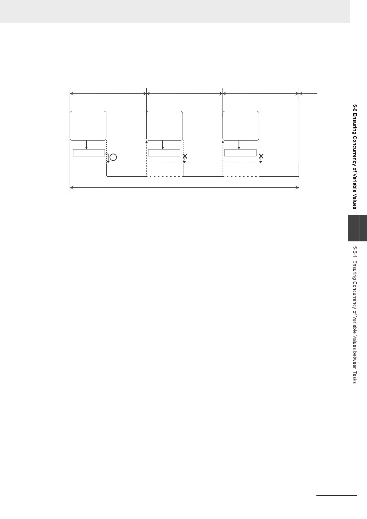
If a refreshing task is set for a global variable, the accessing task, at the start of accessing task exe-
cution, always reads the most recent value of the variable that was written at the completion of
refreshing task execution.
Task period of task A
Task period of task A
Task period of task A
Refreshing
Refreshing
Refreshing
task: Task A
task: Task A
task: Task A
Write
Write
Write
Global variable
Value of
Global variable
Value of variable
Global variable
Value of variable
variable is read.
is not read.
is not read.
Accessing task:
Accessing task:
Accessing task:
Task B
Task B
Task B
Task period of task B
This will allow you to maintain the concurrency of the values of global variables within the tasks with-
out performing any special programming.
If an instruction that writes the value to a global variable is used in the accessing task, an error will
5
occur when you check the program on the Sysmac Studio.
5-43
5 Designing Tasks
Precautions for Correct Use
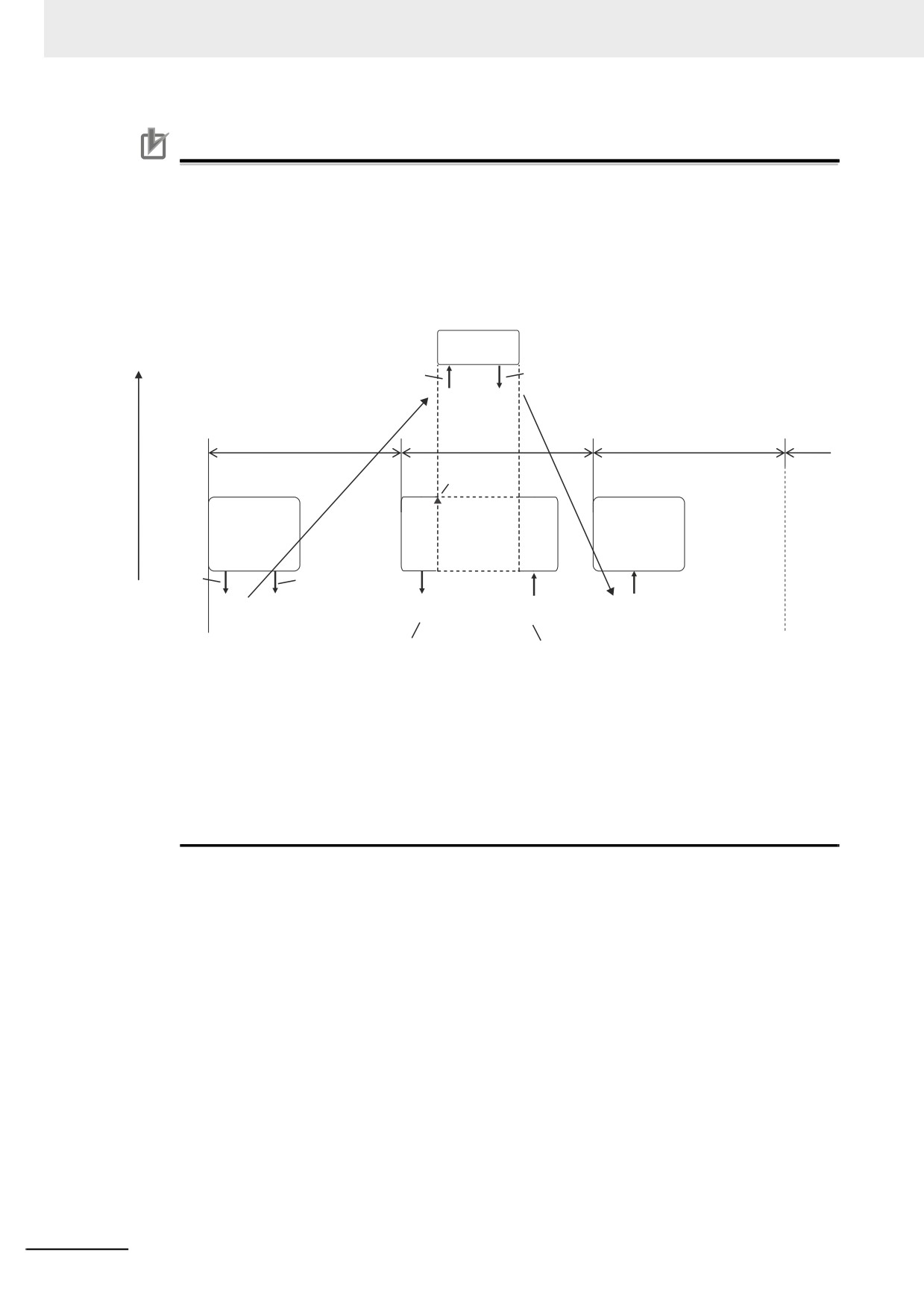
If you are using the ActEventTask instruction between two tasks, you must keep in mind when
the global variables are accessed, and when they are refreshed. For example, in the following
diagram, the value of the GVarA global variable that is accessed from the event task is the value
that was current at the end of task period 1. Therefore, even if the periodic task in task period 2
writes the value of GVarA, that value will not be reflected in the event task. The value that the
event task writes to the GVarB global variable is not passed to the periodic task until the start of
task period 3. Even if the periodic task in task period 2 accesses the value of GVarB, the value
that the event task writes will not be accessed.
Execution
Event task
priority
(refreshing task)
High
A value of 123
A value of 654
is read.
is written.
GVarA
GVarB
The value of GVarA is passed
The value of GVarB is passed to
123
654
to the event task at this point.
the periodic task at this point.
Task period 1
Task period 2
Task period 3
Execution of
ActEventTask
Periodic task
Periodic task
Periodic task
(accessing task)
(accessing task)
(accessing task)
A value of
123 is
written.
A value of 987
A value of 567
A value of
A value of 654 is read.
Low
is written.
987 is read.
is written.
GVarA
GVarB
GVarA
GVarB
GVarB
123
987
567
987
654
The value that is written
The value that the event task
here is not reflected in
writes cannot be accessed.
the event task.
Because of this, do not use exclusive control of variables in tasks to pass the values of global
variables if you are using the ActEventTask instruction to execute event tasks. To ensure the
concurrency of global variables when using the ActEventTask instruction, you should use the
Task_IsActive (Determine Task Status) instruction. The Task_IsActive instruction determines
whether the specified task is in execution or waiting to be executed. Use this instruction to pre-
vent other tasks from accessing variables that the event task writes to while it is in execution.
Refer to the NY-series Instructions Reference Manual (Cat. No. W560) for details on the Task_I-
sActive instruction.
z
Restrictions
• Only one refreshing task can be set for each global variable. If it is necessary to write a global
variable from more than one task, use the task exclusive control instructions described below to
ensure concurrency.
• If you specify a refreshing task for a structure or union variable, you must specify only one refresh-
ing task for the entire structure or union variable. You cannot specify a different refreshing task for
different structure or union members.
• If you specify a refreshing task for an array variable, you must specify only one refreshing task for
the entire array variable. You cannot specify a different refreshing task for different array ele-
ments.
5-44
5 Designing Tasks
Precautions for Correct Use
Do not write the value of a variable for which concurrency is required from any task that is not the
refreshing task, e.g., do not write the value from the accessing task. If you read or write the value
of a variable for which a refreshing task is set from any task that is not a refreshing or accessing
task, the concurrency of the global variable may be lost. If you write such a program, a warning is
given when the program is checked.
Additional Information
You can use a data trace to sample an external variable for a global variable for which settings
for exclusive control of variables in tasks are used. This allows you to sample the values of the
global variable in the refreshing and accessing tasks in a data trace. Refer to 8-4-4 Data Tracing
for information on data tracing.
z Sysmac Studio Setting Procedure
Set the global variables for which to specify refreshing tasks, and set the accessing tasks in Settings
for Exclusive Control of Variables in Tasks under Configurations and Setup - Task Settings
on the Sysmac Studio.
Refer to Settings for Exclusive Control of Variables in Tasks on page 4-10 for details.
5
5-45
5 Designing Tasks
Method 2: Task Exclusive Control Instructions
Use the task exclusive control instructions (i.e., the Lock and Unlock instructions) when it is necessary
to write the value of a global variable from more than one task while maintaining concurrency in the
value of the variable.
The task exclusive control instructions create a lock region from one Lock instruction to the next Unlock
instruction. If a lock region in one task is being executed, the lock regions with the same lock number in
other tasks are not executed. If you place the instructions that write to the global variable in lock
regions, the concurrency of the value is maintained even if you write the value of the variable from more
than one task.
Refer to information on the Lock and Unlock instructions in the NY-series Instructions Reference Man-
ual (Cat. No. W560) for details.
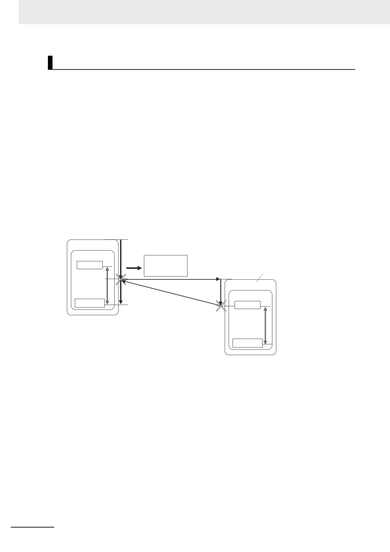
Example:
In this example, task A and task B both have lock region 1. The priority of task B is higher than the pri-
ority of task A.
If the execution condition for task B is met during execution of lock region 1 in task A, execution of task
A is paused during lock region 1 and task B is executed. However, in this case, lock region 1 in task A is
not completed, so task B is paused before it processes lock region 1. When task B is paused, execution
of lock region 1 in task A is started again.
Task A
Program
Executed.
Lock instruction
Global variable
Refreshed.
Higher priority
Task B
Lock region 1
Executed.
Executed.
Program
Unlock instruction
Lock instruction
Execution is not
started until
execution of region
Lock region 1
1 in task A is
completed.
Unlock instruction
5-46
5 Designing Tasks
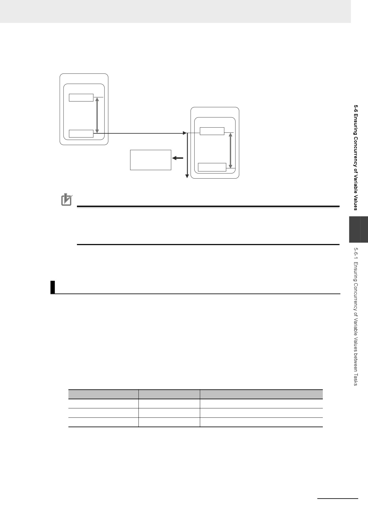
When execution of lock region 1 in task A is completed, task A is paused again and the remainder of
lock region 1 in task B is executed. The concurrency of the value of the global variable is maintained by
implementing exclusive control of the write processing of the global variable between the tasks.
Task A
Program
Lock instruction
Task B
Lock region 1
Program
Lock instruction
Unlock instruction
Executed.
Lock region 1
Refreshed.
Global variable
Unlock instruction
Precautions for Correct Use
• Do not make the locked regions any longer than necessary. If the lock regions are too long,
the task execution period may be exceeded.
5
• Always use the Lock and Unlock instructions together as a set in the same section of the same
POU.
Example of Accessing the Same Global Variable between Tasks
This section describes how to request processing to another task with multiple global variables.
The following sample programming uses one global variable gReq as an exclusive flag for processing
to perform exclusive control in the user program. Even in this case, exclusive control of variables in
tasks is required for the access logic to the gPar1, gPar2, and gReq global variables that are used
between tasks.
A sample programming that uses the task exclusive control instructions (i.e., the Lock and Unlock
instructions) to perform exclusive control is shown.
z Global Variables
Name
Data type
Comment
gReq
BOOL
Request flag
gPar1
ULINT
Parameter 1
gPar2
DATA_AND_TIME
Parameter 2
5-47
5 Designing Tasks
z
Task That Makes Processing Requests (MainTask)
• Internal Variables
Name
Data type
Comment
ReqTrg
BOOL
Request trigger
cCnt
ULINT
100-ms counter value
cTime
DATA_AND_TIME
Current time
• ST Program
cCnt:=Get100msCnt();
(* Get the 100-ms counter value. *)
cTime:=GetTime();
(* Get the current time. *)
Lock(1);
(* Start an exclusive lock between tasks. *)
IF ReqTrg=TRUE AND gReq=FALSE THEN
(* Access the exclusive flag. *)
gPar1:=cCnt;
(* Set the parameter to process in SubTask. *)
gPar2:=cTime;
(* Set the parameter to process in SubTask. *)
gReq:=TRUE;
ReqTrg:=FALSE;
END_IF;
Unlock(1); (* Stop an exclusive lock between tasks. *)
z
Task That Receives Processing Requests (SubTask)
• Internal Variables
Name
Data type
Comment
ReqBusy
BOOL
---
UserDefFB_ins
UserDefFB
User-defined function block instance that exe-
cutes processing
• ST Program
Lock(1);
(* Start an exclusive lock between tasks. *)
IF ReqTrg=TRUE AND gReq=FALSE THEN
(* Access the exclusive flag. *)
ReqBusy:=TRUE;
UserDefFB_ins.PutData:=gPar1;
(* Read the parameter from MainTask. *)
UserDefFB_ins.PutData:=gPar2;
(* Read the parameter from MainTask. *)
gReq:=FALSE;
(* Reset the exclusive flag. *)
UserDefFB_ins.Execute:=TRUE;
END_IF;
Unlock(1);
(* Stop an exclusive lock between tasks. *)
UserDefFB_ins();
IF UserDefFB_ins.Done:=TRUE THEN
UserDefFB_ins.Execute:=FALSE;
ReqBusy:=FALSE;
END_IF;
5-48
5 Designing Tasks
5-6-2
Variable Access from Outside the Controller
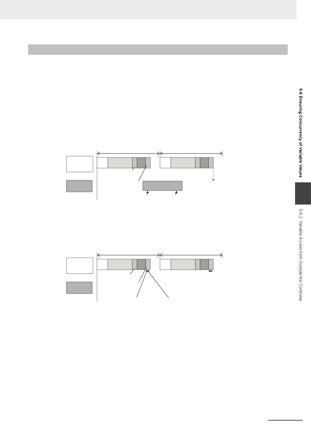
A variable access from outside the Controller is executed during the system service. The system ser-
vice has a lower execution priority than tasks. This means, if multiple variables are accessed from out-
side the Controller, refreshing all variable values may not be completed in a task period. If refreshed
variables and not-refreshed variables are mixed in the user program, the Controller may perform unin-
tended operation.
To avoid this, make the variable access from outside the Controller be executed during the system
common processing 2 of the task. By making this, multiple variable values can be securely refreshed in
the same task period.
z Accessing Variables from Outside the Controller during the System Service
The access to multiple variables may not be completed in the same task period.
Primary period
Primary period
Primary
IO
UPG
MC
IO
UPG
MC
periodic task
System common
processing 1
System
System common
SS
services
processing 2
5
Variable access 1 from
Variable access 2 from
outside the Controller
outside the Controller
z Accessing Variables from Outside the Controller during the System Common
Processing 2
The access to multiple variables is securely executed in the same task period.
Primary period
Primary period
Primary
IO
UPG
MC
IO
UPG
MC
periodic task
System common
processing 1
System
System common
services
processing 2
Variable access 1 from
Variable access 2 from
outside the Controller
outside the Controller
5-49
5 Designing Tasks
This section particularly describes how to execute the variable access from outside the Controller
during the system common processing 2 of the task.
Methods to Access Variables From Outside the Controller
There are the following four methods to access variables from outside the Controller.
• Sysmac Studio
• NA/NS-series PT
• EtherNet/IP tag data links
• CIP communications instruction from the host computer
If the Sysmac Studio is used to access variables, it can only refresh the variable values during the sys-
tem common processing 2 of the task. Values are accessed during the system services.
Tasks that Execute Variable Access during the System Common
Processing 2
The tasks that execute variable access from outside the Controller during the system common process-
ing 2 are predetermined as follows according to the variable types.
Variable
Task that update values
Global variables specified in the settings for exclu-
The refreshing task specified in Settings for Exclusive
sive control of variables in tasks
Control of Variable in Tasks under Configurations
and Setup - Task Settings on the Sysmac Studio.
Device variables for EtherCAT slaves
Tasks specified in I/O Control Task Settings under Con-
figurations and Setup - Task Settings on the Sysmac
Studio.
Settings for Executing Variable Access during the System Common
Processing 2
To access variables from outside the Controller during the system common processing 2, it is neces-
sary to make the following two settings on the Sysmac Studio.
• Settings for exclusive control of variables in tasks (when the target variables are the global variables)
• Settings for variable access time
Settings for Exclusive Control of Variables in Tasks
If global variables are accessed from outside the Controller during the system common processing 2 of
the task, it is necessary to make setting for exclusive control of variables in tasks. The exclusive control
of variables in tasks refers to the function that specifies the task that can refresh the target global vari-
able. This function prevents the target variable from being updated by other tasks or by other methods
to access variables from outside the Controller.
Refer to Settings for Exclusive Control of Variables in Tasks on page 4-10 for the details on the exclu-
sive control of variables in tasks.
Precautions for Correct Use
When you use EtherNet/IP tag data links, always specify the same task as the refreshing task for
all tags (variables that have Network Publish attribute) in the same tag set. Otherwise, multiple
tags in a tag set may be refreshed in separate task periods.
5-50
5 Designing Tasks
Settings for Variable Access Time
When variable access from outside the Controller is executed during the system common processing 2
of the task, the task execution time may be longer. The user must set the upper limit of the processing
time for accessing variables on the Sysmac Studio. The variable access time refers to the upper limit of
the processing time for accessing variables.
z
Calculating Variable Access Time
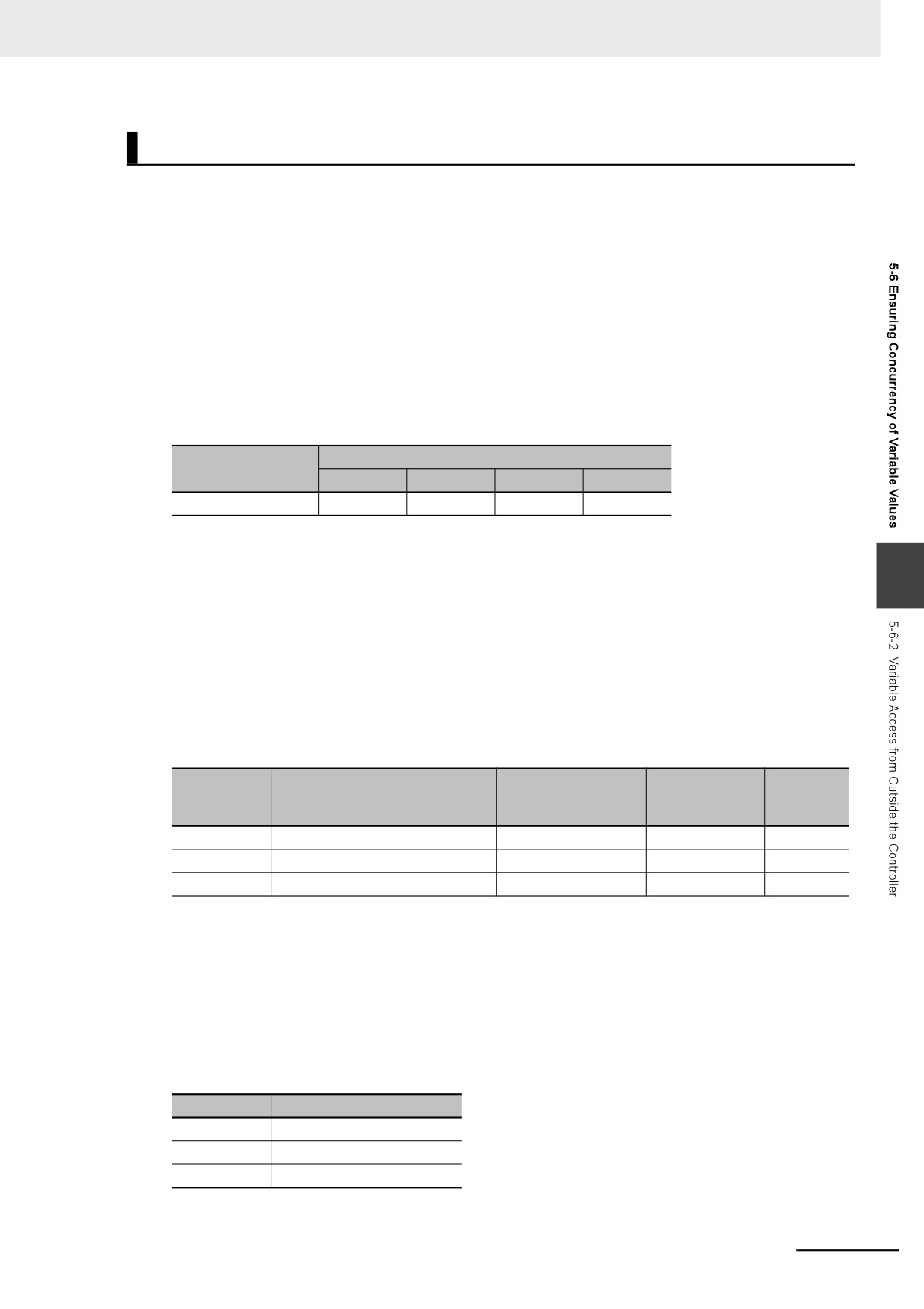
Use the following equation for calculating the variable access time.
Variable access time [μs] = total size of variables [bytes] * a + number of variables * b + number of
accesses * c + d
The values of the constants a to d in above equation are given in the following table for the NY-
series Controller.
Controller model
Constant value [μs]
number
a
b
c
d
NY52-
0.0006
0.100
1.40
6.60
z
Setting Variable Access Time
Set the variable access time in the Configurations and Setup − Task Settings on the Sysmac Stu-
5
dio. The setting must be made for each task by entering the ratio to the task period. The default
value is 3%. For the details on the settings, refer to the Sysmac Studio Version 1 Operation Manual
(Cat. No. W504).
z
Example of Variable Access Time Setting
The following is an example of variable access time setting.
In this example, it is assumed that there are the following three variable accesses from outside the
Controller to the task that operates in the NY52-.
Total size of vari-
Number of vari-
Number of
Access No.
Source of variable access
ables to access
ables to access
accesses
[bytes]
1
EtherNet/IP tag data link
600
8
1
2
EtherNet/IP tag data link
200
4
1
3
CIP communications instruction
1,000
1
1
Using the equation, the variable access time for Access No.1 is calculated as follows.
Variable access time for Access No.1 = 600 * 0.0006 + 8 * 0.100 + 1 * 1.40 + 6.60
= 9.16 [μs]
In the same way, you can calculate the access time for the other accesses and get the following val-
ues.
Access No.
Variable Access Time [μs]
1
9.16
2
8.52
3
8.7
5-51
5 Designing Tasks
If only one of these accesses occurs in one task period, you set the variable access time to the one
for Access No.1, which requires the longest access time.
The variable access time for Access No.1 is 9.16 μs. Therefore, when the task period is 500 μs, the
variable access time is set to 9.16/500 ≈ 2%.
If every access occurs once in one task period, the variable access time is calculated with the equa-
tion as follows.
Variable access time = (600 + 200 + 1000) * 0.0006 + (8 + 4 + 1) * 0.100 + (1 + 1 + 1) * 1.40 + 6.60
= 13.18 [μs]
When the task period is 500 μs, the variable access time is set to 19.08/500 ≈ 4%.
z
Processing in the Case That Actual Variable Access Time Became Longer
Than Set Value
If actual variable access time became longer than the set value, the following processing is per-
formed depending on the number of variable accesses in one task period.
Set a sufficiently long access time so that multiple variable accesses can be completed within a task
period.
Number of vari-
able accesses in
Processing
one task period
Multiple times
Variable accesses are executed for the number of times that can be completed within
the set variable access time. The rest of accesses that could not be done will be exe-
cuted in the next task period.
This means, the multiple variable accesses cannot be completed within the same task
period.
Once
Variable accesses continue even after the set variable access time is exceeded. This
means, the task execution time gets longer.
5-52
5 Designing Tasks
5-7
Errors Related to Tasks
This section describes the following errors.
• Task Period Exceeded
• Motion Control Period Exceeded
• Task Execution Timeout
• I/O Refreshing Timeout Error
Task Period Exceeded
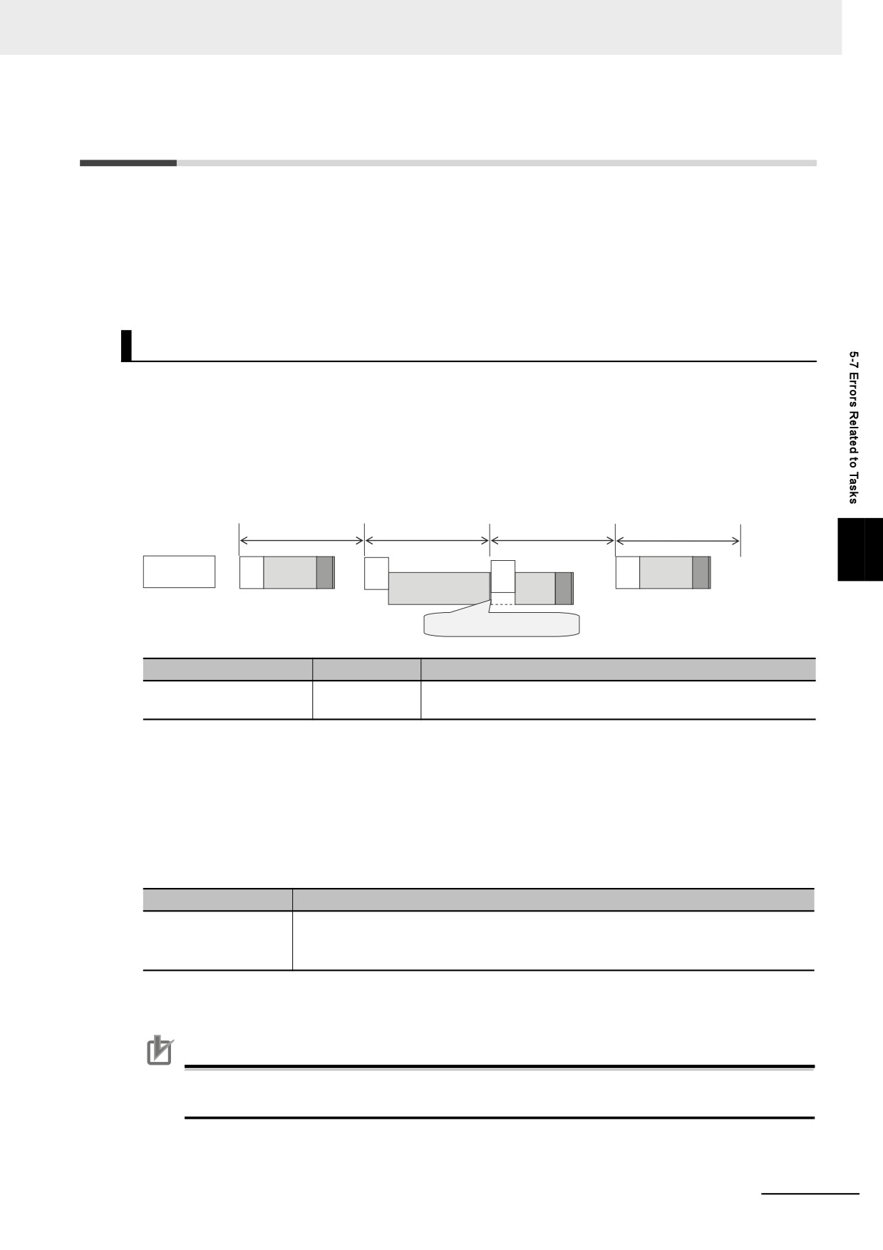
A Task Period Exceeded error occurs if the task execution time exceeds the specified task period.
This is a minor fault level Controller error. Operation continues even when this error occurs.
It can occur for the primary periodic task and periodic tasks.
You can also disable the Task Period Exceeded errors with a setting. Use the Task Period Exceeded
Detection setting in the Task Settings of the Sysmac Studio. The default setting is to detect the error.
Task period
Task period
Task period
Task period
5
Primary
IO
UPG MC
IO
IO
UPG MC
periodic task
IO
UPG
MC
Task Period Exceeded
occurred.
Error name
Error level
Correction
Task Period Exceeded
Minor fault
Review the task settings and programs and download the project
again. Reset the error from the Sysmac Studio.
Even if the Task Period Exceeded Detection setting is disabled, information will be output to the follow-
ing system-defined variables if task processing is not completed within the period: Task Period
Exceeded Flag (_TaskName_Exceeded), Task Period Exceeded Count (_TaskName_ExceedCount),
Controller Error Status (_ErrSta), and the event log.
I/O is refreshed as follows according to what the I/O is for if task processing is not completed within the
task period.
I/O is for
I/O refresh operation if task processing is not completed within the task period
EtherCAT slave*1
Outputs: The values from the previous period are output.
Inputs: Inputs are refreshed, but the input data is not updated in the executed user pro-
gram.
*1
This includes NX Units on EtherCAT Slave Terminals.
Precautions for Correct Use
If the Task Period Exceeded error occurs, shorten the programs to fit in the task period or
increase the setting of the task period.
5-53
5 Designing Tasks
Motion Control Period Exceeded
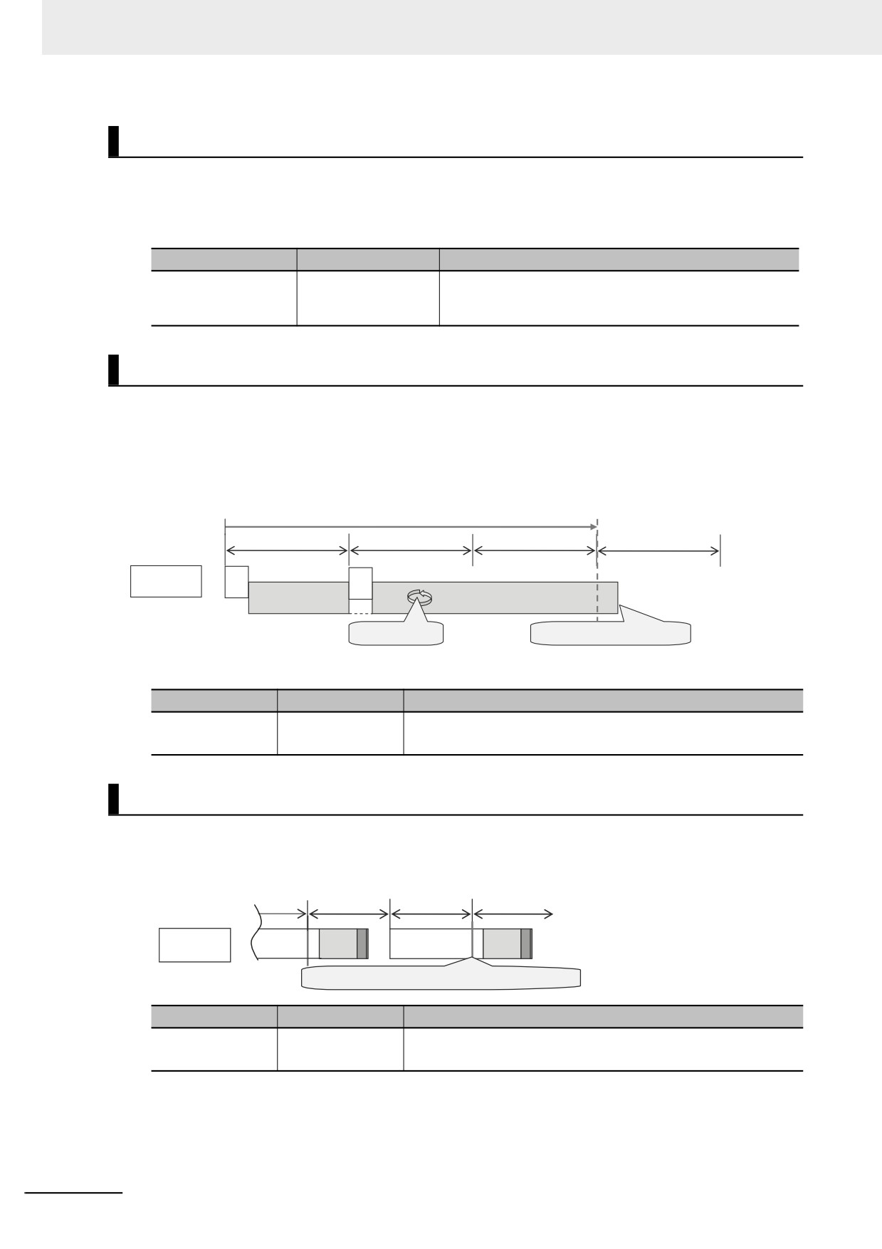
A Motion Control Period Exceeded error occurs if the motion control processing (MC) is not completed
within the primary period (i.e., the motion control period) twice or more in a row. A partial fault level Con-
troller error will occur in the Motion Control Function Module. A Task Period Exceeded error will occur at
the same time.
Error name
Error level
Correction
Motion Control Period
Partial fault
Reduce the amount of processing in the programs or
Exceeded
increase the control period within the range that does not
adversely affect operation.
Task Execution Timeout
A Task Execution Timeout error occurs if task processing is not completed within the specified timeout
detection time.
This is a major fault level Controller error. Execution of the user program stops when the error occurs.
This error also occurs when normal task operation is not possible due to errors in program logic, such
as infinite loops.
Timeout Detection Time
Primary period
Primary period
Primary period
Primary period
Primary
IO
IO
periodic task
UPG
Infinite loop, etc.
Task Execution Timeout occurred.
Error name
Error level
Correction
Task Execution
Major fault
Review the task settings and download the user program again.
Timeout
The power supply must be cycled or the Controller reset.
I/O Refreshing Timeout Error
An I/O Refreshing Timeout Error occurs when I/O refreshing for the primary periodic task is not com-
pleted within the period twice or more in a row.
This is a major fault level Controller error. Execution of the user program stops when the error occurs.
Primary period
Primary period
Primary period
Primary period
Primary
M
M
IO
UPG
IO
UPG
periodic task
C
C
I/O Refreshing Timeout Error occurred twice or more.
Error name
Error level
Correction
I/O Refreshing
Major fault
Review the task settings and download the project again.
Timeout Error
The power supply must be cycled or the Controller reset.
5-54
5 Designing Tasks
5-8
Monitoring Task Execution Status and Task
Execution Times
You can use online operations from the Sysmac Studio to monitor the task execution status and task
execution times.
Monitoring Task Execution Status
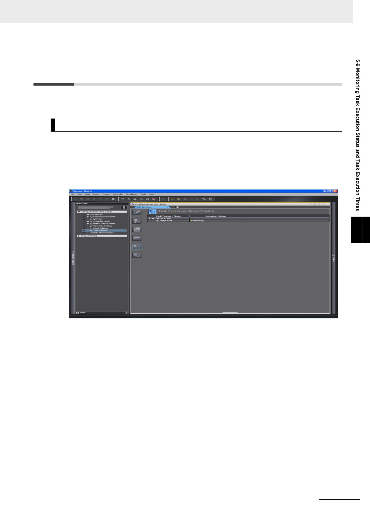
You can monitor the execution status of the programs in all of the tasks (started/stopped) from the Sys-
mac Studio.
z Sysmac Studio Operation
Place the Sysmac Studio online with the Controller and select Configurations and Setup − Task
Settings. Click the Task Execution Status Monitor Button to display the following window.
5
5-55
5 Designing Tasks
Task Execution Time Monitor
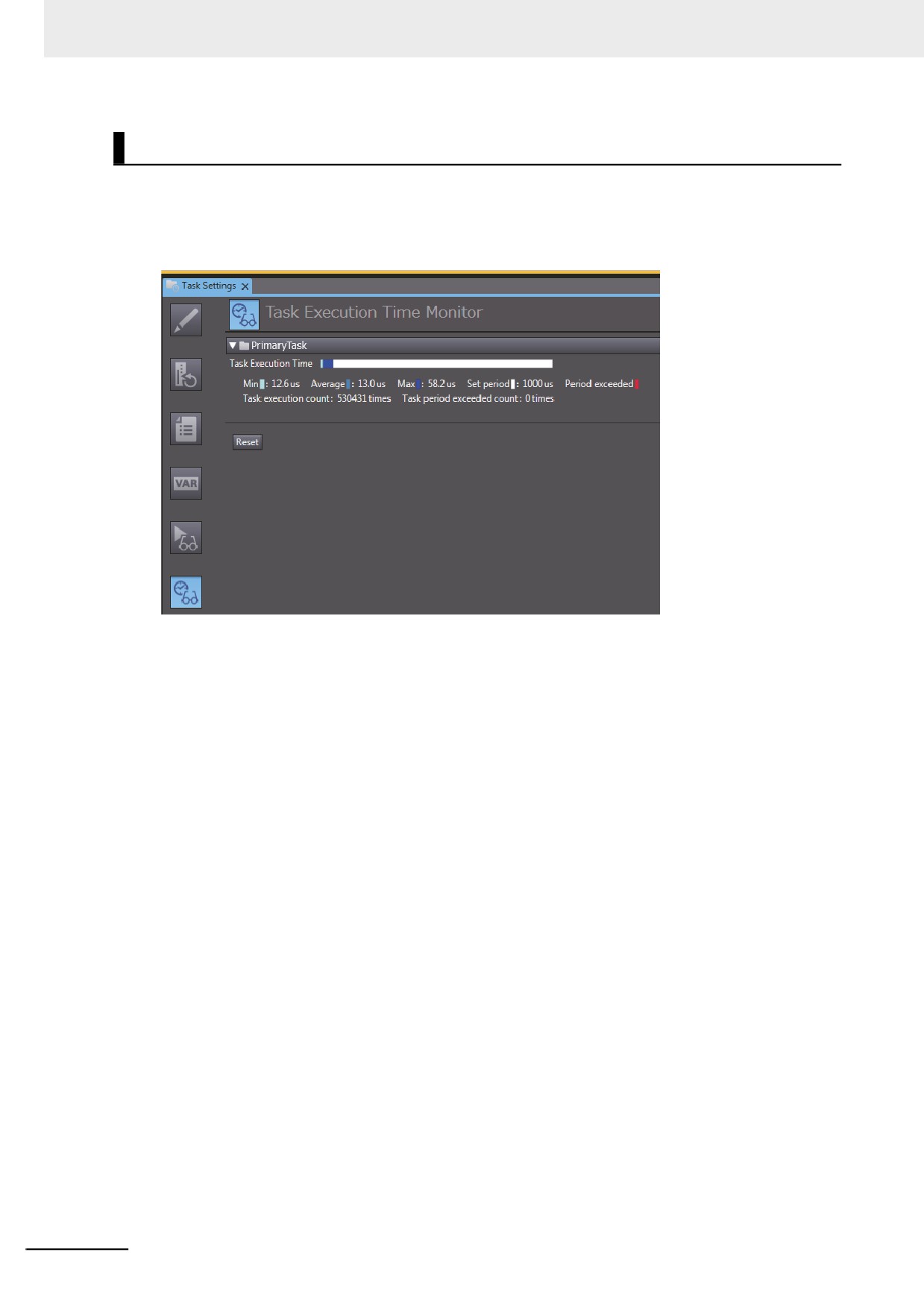
You can monitor the execution time of each task from the Sysmac Studio.
z Values You Can Monitor from the Sysmac Studio
Connected to the Controller
5-56
5 Designing Tasks
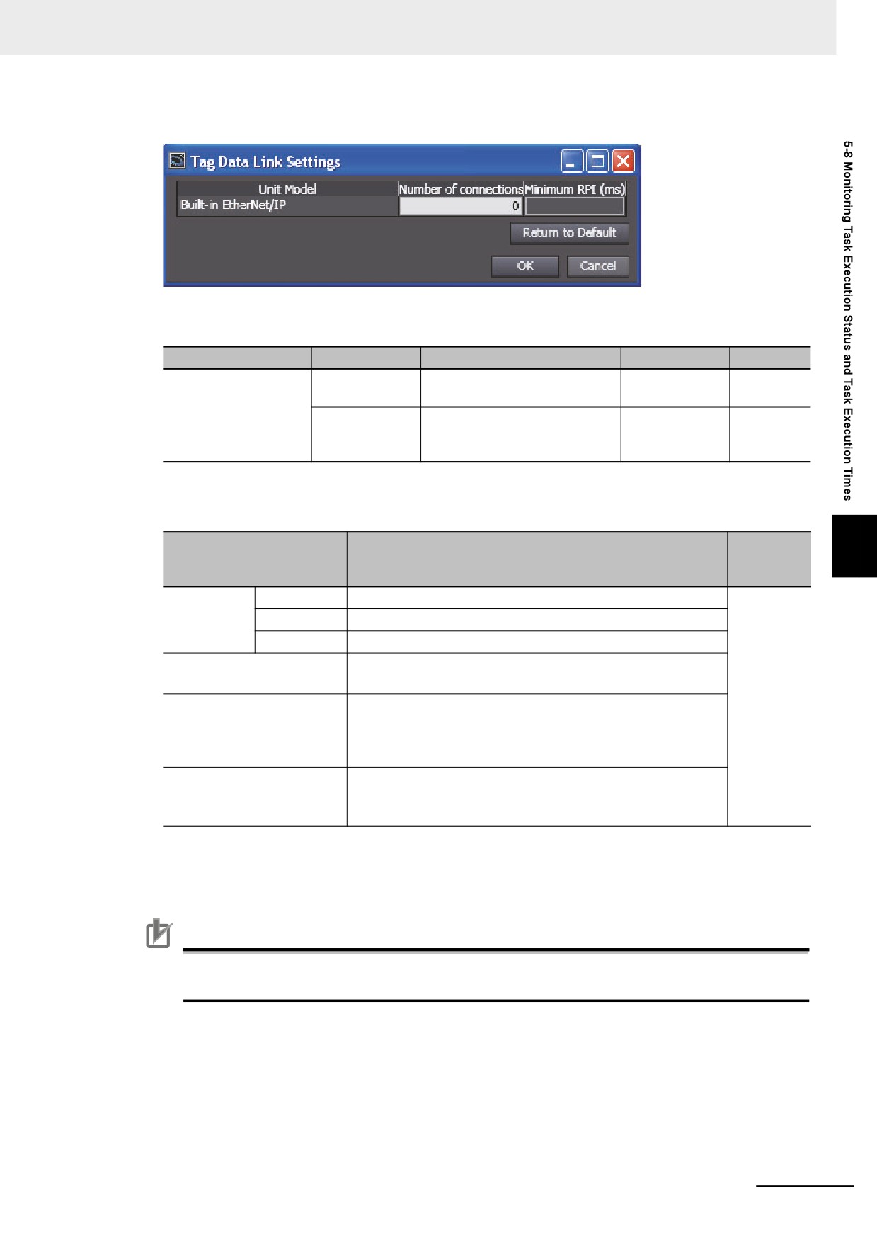
Built-in EtherNet/IP Dialog Box for Simulator Connection
The parameters are listed in the following table.
Port that is used
Parameter
Description
Set values
Default
Built-in EtherNet/IP
Number of con-
This is the number of tag data
0 to 128
0
port on NY-series Con-
nections
link connections.
troller
Minimum RPI
This is the lowest packet inter-
1 ms to 10 s in
---
val (RPI) that is set for all of the
1-ms incre-
tag data link connections.
ments
You can monitor the following items.
Connected
5
Monitor item
Description
to the Con-
troller
Task execu-
Min.
The minimum value of the task execution time.
Displayed.
tion time*1
Average
The average value of the task execution time.
Max.
The maximum value of the task execution time.
Set period
The specified task period.*2
Period exceeded
If the task execution time exceeds the task period (i.e., if the
Task Period Exceeded Flag system-defined variable is TRUE),
the amount by which the time was exceeded is displayed in the
bar. 2
Task execution count
Displays the number of executions of the task.
The value of the Task Execution Count system-defined variable is
displayed.
*1
This is the actual time required from the point that task execution was started until it was completed. This
interval includes both the time to execute other tasks and the time for system services that were executed
from when task execution was started until it was completed.
*2
This item is not displayed for event tasks.
Precautions for Correct Use
Always confirm operation while connected to the physical Controller to study the designs and
before starting actual system operation.
5-57
5 Designing Tasks
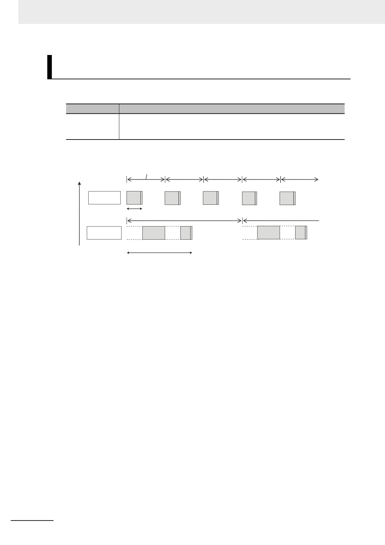
Meaning of the Task Execution Time and the Real Processing Time
of the Task
The Task Execution Time and Real Processing Time of Tasks that are displayed in the Monitor View for
the execution time of tasks are described in the following table.
Displayed time
Meaning
Task execution
This is the time from when the task period starts until task processing ends.
time
However, this includes the time when the periodic task is interrupted for execution of
tasks with higher execution priorities.
Execution
priority
Task period of primary periodic task
High
Primary
periodic task
a
Task period of periodic task
Periodic task
Interrupted.
Interrupted.
Interrupted.
Interrupted.
Low
b
a: Task execution time of primary periodic task
b: Task execution time of periodic task
5-58
5 Designing Tasks
5-9
Task Design Methods and I/O
Response Times
This section provides guidelines for designing tasks, information on estimating task execution times, an
example of task designing, and information on I/O response times.
The primary periodic task and periodic tasks of an NY-series Controller operate according to the speci-
fied task periods.
If the actual execution time exceeds the task period, an error occurs.
This section uses an example that consists of one primary periodic task to describe estimation and
appraisal methods.
Precautions for Correct Use
The task execution times in the physical Controller depends on the logic operations that are per-
formed in the user program, the presence of communications commands and data links, on
whether data tracing is performed, and on other factors.
Before starting actual operation, you must test performance under all foreseeable conditions on
the actual system and make sure that the task periods are not exceeded and that suitable com-
munications performance is achieved.
5
5-9-1
Checking the Task Execution Time
Always design your system so that the average and maximum task execution times that are estimated
with the methods that are described in this section sufficiently fit within the specified task periods.
z Desktop Calculations
First, refer to A-2 Calculating Guidelines for the Real Processing Times of Tasks for the NY-series
System to make a rough estimate of the average task execution time on paper.
You cannot estimate the maximum value on paper.
z Calculating Times on the Physical Controller
You can check the following values in the Task Execution Time Monitor when you are connected to
the physical Controller.
• The minimum, average, and maximum values of the task execution time
• Set period
• Task execution count
• Number of times the task period was exceeded (Task Period Exceeded Count)
The maximum values that are displayed on the Sysmac Studio are the results of operation on the
physical Controller.
As described previously, the maximum value of the task execution time varies depending on the
internal status of the physical Controller.
Additional Information
The average values of the task execution times that are displayed for task execution time moni-
toring are the averages for 10 task execution times.
5-59
5 Designing Tasks
5-9-2
Examples of Task Design
This section provides the design procedure for a project that consists of only the primary periodic task.
In any actual application or for specific conditions, you need to consider any elements for which the
design procedure must be changed. This example is therefore for reference only.
1 Find the I/O response times that are required for the system from the equipment specifications.
2 From the system I/O response times, determine the task period for the primary periodic task.
3 See if the task execution time fits into the task period that you determined.
Then, work on paper to estimate the average of the task execution time.
4 Use the physical Controller to see if the task execution time fits into the task period.
Place the Sysmac Studio online with the physical Controller and use Task Execution Time Mon-
itor to check the task execution times.
z If Only the Primary Periodic Task Is Too Large to Fit the Specified Task Period,
Consider Separating It into Periodic Tasks As Follows.
• To reduce the task execution time, use the Enable Program (PrgStart) and Disable Program
(PrgStop) instructions to execute the program assigned to the primary periodic task only when
necessary.
• If the primary periodic task will still not fit within the specified task period after these measures,
among the processes of primary periodic task, assign those which do not require the high-speed
or high-accuracy control to the priority-16 periodic task.
However, if variables such as the Axis Variables are accessed between the primary periodic task
and the priority-16 periodic task, the task execution time for the primary periodic task may be lon-
ger. Refer to the NY-series Industrial Panel PC / Industrial Box PC Motion Control User's Manual
(Cat. No. W559) for details.
• If the primary periodic task will still not fit within the specified task period even after you take all of
these measures, change the task period for the primary periodic task.
5-60
5 Designing Tasks
5-9-3
System Input and Output Response Times
The times that are required for the system to produce an output after it receives an input are described
in this section.
The I/O response times depend on various conditions.
The input response times and output response times between external devices and the slaves and
Units must be added to the system I/O response times.
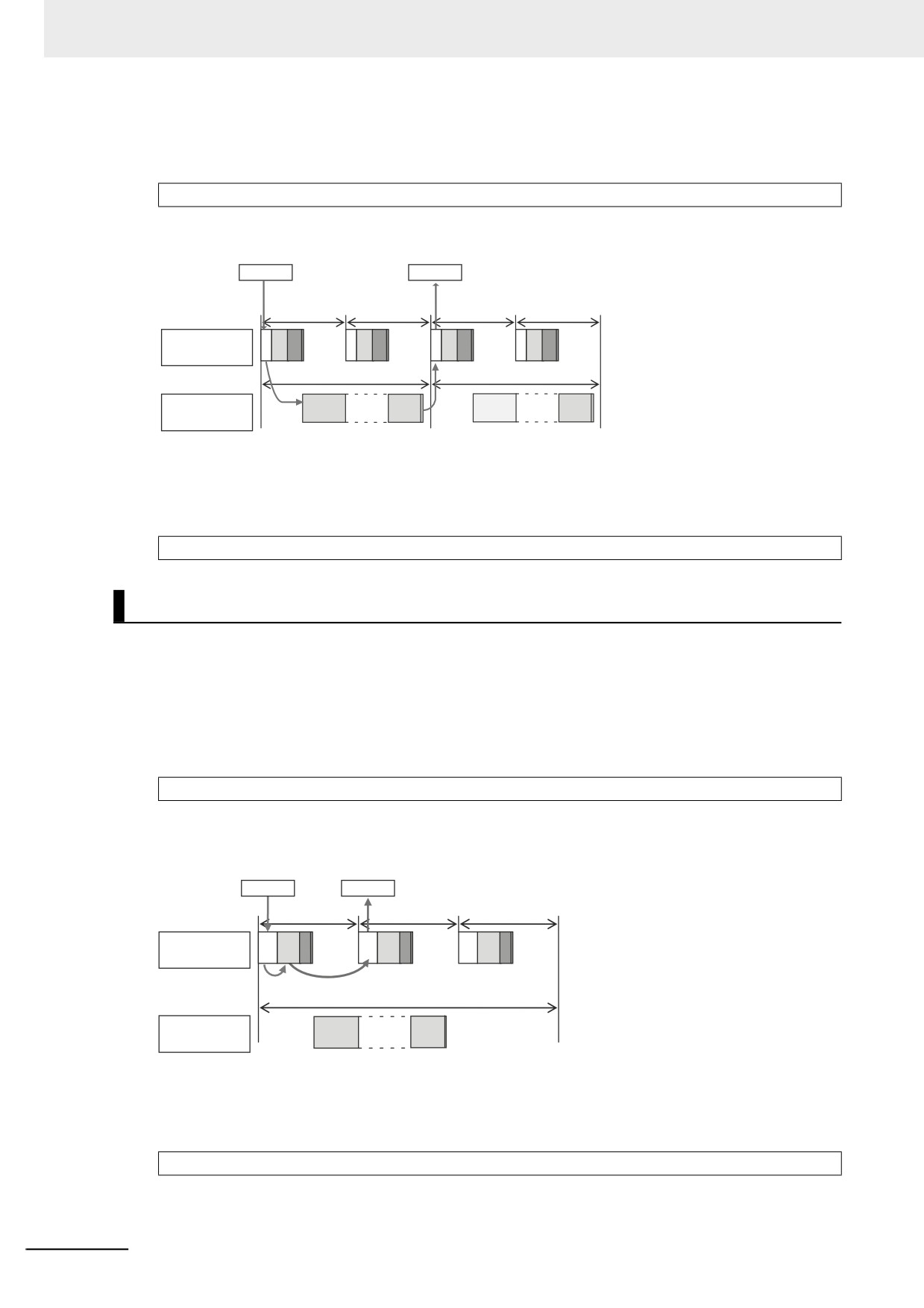
Sequence Control with Basic I/O Units
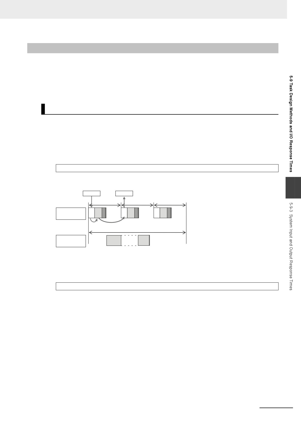
I/O refreshing between Basic I/O Units and external devices is performed in the task to which I/O
refreshing is assigned.
The I/O response times that include EtherCAT communications times are given below.
z Performing Control with the Programs in the Primary Periodic Task
The Controller makes a response in the following I/O response time.
Minimum I/O response time = Primary period
Example: Controlling Unit A and Unit B with the Primary Periodic Task
5
Unit A
Unit B
Primary period (t)
Primary
M
M
M
IO
UPG
IO
UPG
IO
UPG
periodic task
C
C
C
Task period 1 (e.g., t × 3)
Priority-16
UPG
periodic task
Note: The above diagram shows only one input and one output.
However, the I/O response time may be as follows depending on the timing of the input from the
Unit.
Maximum I/O response time = Primary period × 2
5-61
5 Designing Tasks
z Performing Control with the Programs in the Priority-16 Periodic Task
The Controller makes a response in the following I/O response time.
Minimum I/O response time = Priority-16 periodic task period
Example: Controlling Unit A and Unit B with the Priority-16 Periodic Task
Unit A
Unit B
IN
OUT
Primary period
Primary
IO
UPG MC
IO
UPG MC
IO
UPG MC
IO
UPG MC
periodic task
Task period
Priority-16
UPG
UPG
periodic task
Note: The above diagram shows only one input and one output.
However, the I/O response time may be as follows depending on the timing of the input from the
Unit.
Maximum I/O response time = Priority-16 periodic task period × 2
Sequence Control with EtherCAT Slaves
For EtherCAT slaves, EtherCAT communications with external devices is performed for I/O refreshing
in the primary periodic task.
The I/O response times that include EtherCAT communications times are given below.
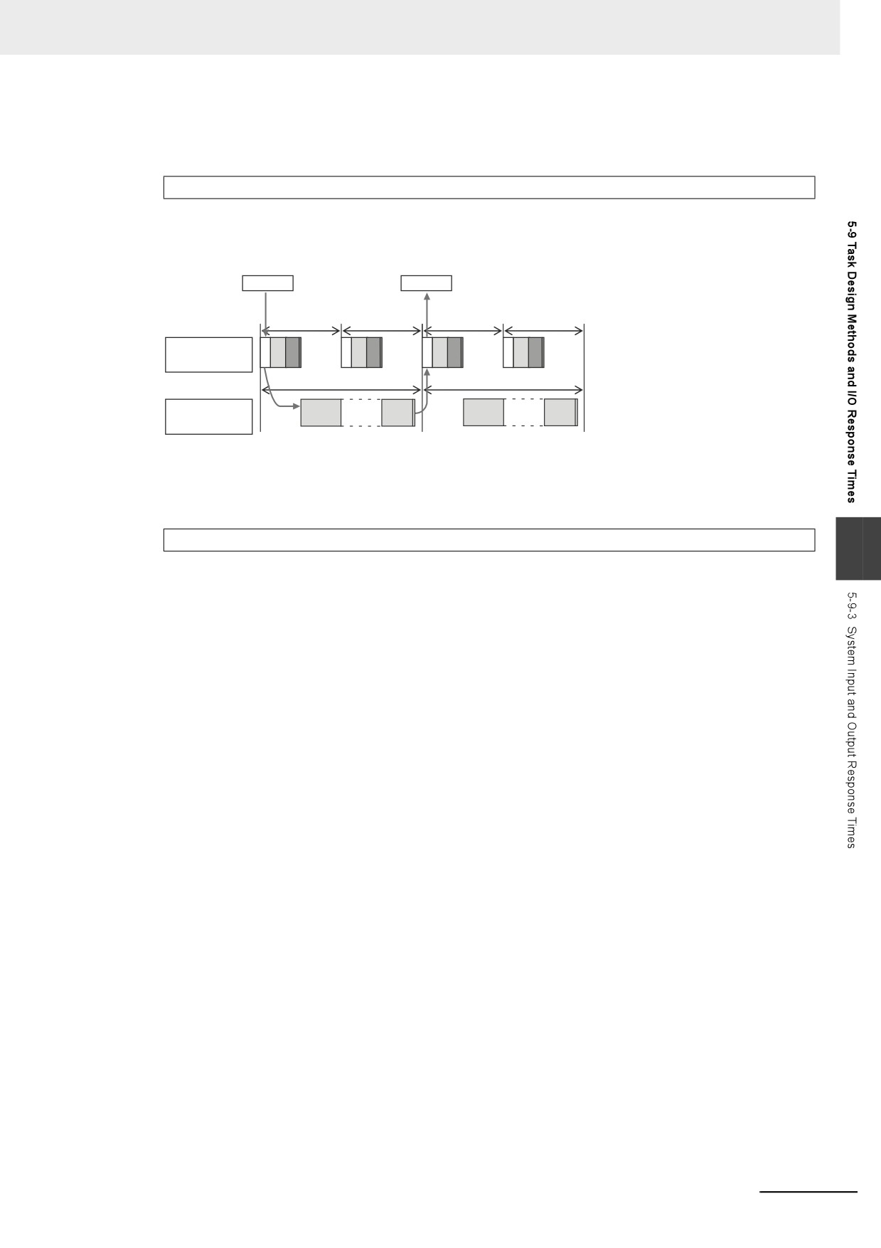
z Performing Control with the Programs in the Primary Periodic Task
The Controller makes a response in the following I/O response time.
Minimum I/O response time = Primary period (= process data communications cycle)
Example: Controlling EtherCAT Input Slave A and EtherCAT Output Slave B with the Primary Peri-
odic Task
Slave A
Slave B
Process data
communications period =
Primary period (t)
Primary
M
M
M
IO
UPG
IO
UPG
IO
UPG
periodic task
C
C
C
Task period 1 (e.g., t × 3)
Priority-16
UPG
periodic task
Note: The above diagram shows only one input and one output.
However, the I/O response time may be as follows depending on the timing of the input from the
slave.
Maximum I/O response time = Primary period (= process data communications cycle) × 2
5-62
5 Designing Tasks
z Performing Control with the Programs in the Priority-16 Periodic Task
The Controller makes a response in the following I/O response time.
I/O response time = Priority-16 periodic task period
Example: Controlling EtherCAT Input Slave A and EtherCAT Output Slave B with the Priority-16
Periodic Task
Slave A
Slave B
IN
OUT
Process data
communications cycle
= Primary period (t)
Primary
IO
UPG MC
IO
UPG MC
IO
UPG MC
IO
UPG MC
periodic task
Task
period
Priority-16
UPG
UPG
periodic task
Note: The above diagram shows only one input and one output.
However, the I/O response time may be as follows depending on the timing of the input from the
slave.
Maximum I/O response time = Priority-16 periodic task period × 2
5
5-63