Omron IPC Machine Controller Industrial Panel PC / Industrial Box PC. Software User’s Manual (Industrial PC Platform NY-series) - page 4
I/O Ports, Slave Configuration,
and Unit Configuration
3
This section describes how to use I/O ports, how to create the Slave and Unit Configu-
rations, and how to assign functions.
3-1
Procedure to Create the Slave and Unit Configurations
3-2
3-2
Creating the EtherCAT Slave Configuration
3-4
3-3
I/O Ports and Device Variables
3-5
3-3-1
I/O Ports
3-5
3-3-2
I/O Port Names
3-6
3-3-3
Device Variables
3-6
3-4
Allocating Variables to Units
3-8
3-4-1
Procedure to Assign Variables to Units
3-8
3-4-2
Using Variables Assigned to Units
3-9
3-5
Creating the Axes and Assigning Them to the Servo
Drives/Encoder Input Slaves
3-11
3-5-1
Introduction
3-11
3-5-2
Axis Variables and Axes Group Variables
3-12
3-5-3
Creating and Using Axes and Axis Variables
3-14
3-1
3 I/O Ports, Slave Configuration, and Unit Configuration
3-1
Procedure to Create the Slave and
Unit Configurations
This section provides the procedures for the Slave and Unit Configurations.
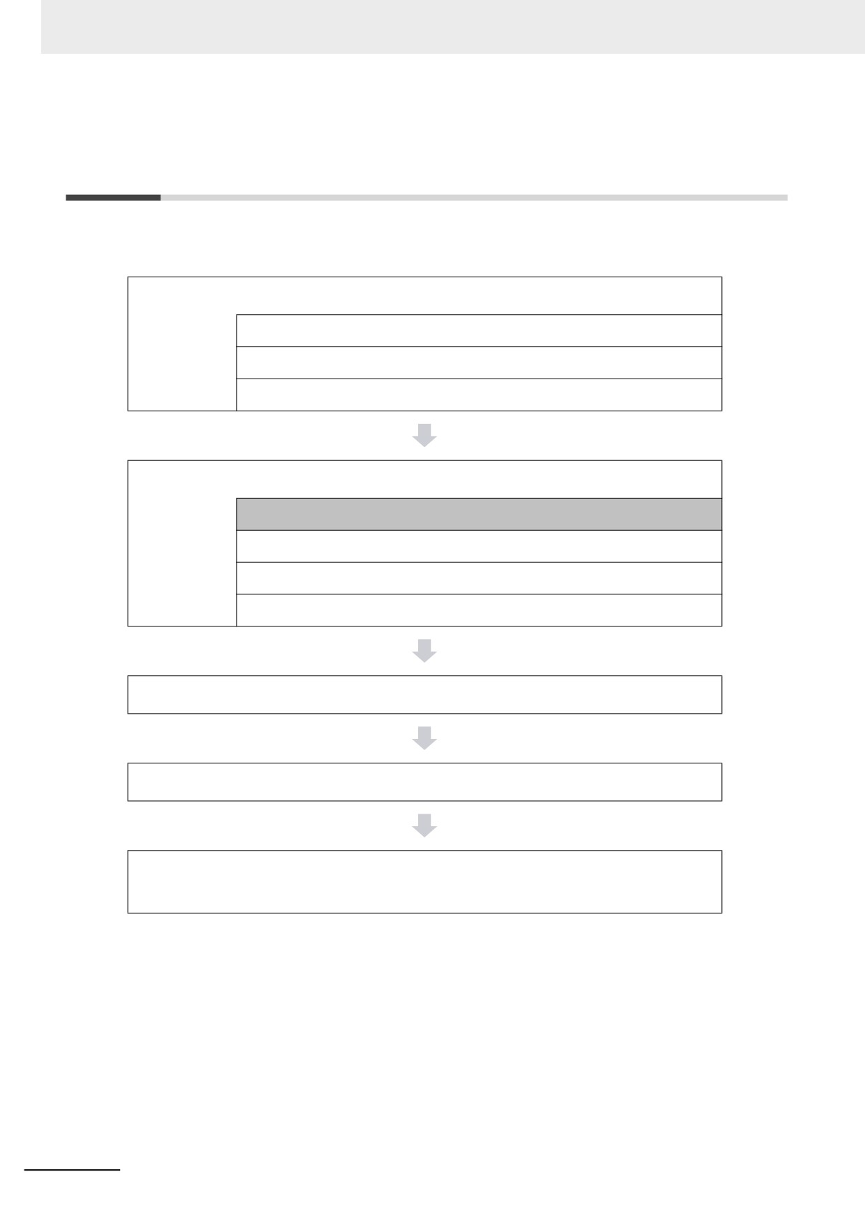
The shaded steps in the overall procedure that is given below are for the Slave and Unit Configurations.
Step 1. Software Design
Step 1-1 Designing I/O and Processing
Step 1-2 Designing Tasks
Step 1-3 Designing Programs
Step 2. Software Setups and Programming
Step 2-1 Slave and Unit Configurations
Step 2-2 Controller Setup
Step 2-3 Programming
Step 2-4 Offline Debugging
Step 3. Mounting and Setting Hardware
Step 4. Wiring
Step 5. Checking Operation and Starting Operation on the
Actual System
For details, refer to 1-4 Overall Operating Procedure for the NY-series Controller.
3-2
3 I/O Ports, Slave Configuration, and Unit Configuration
Reference
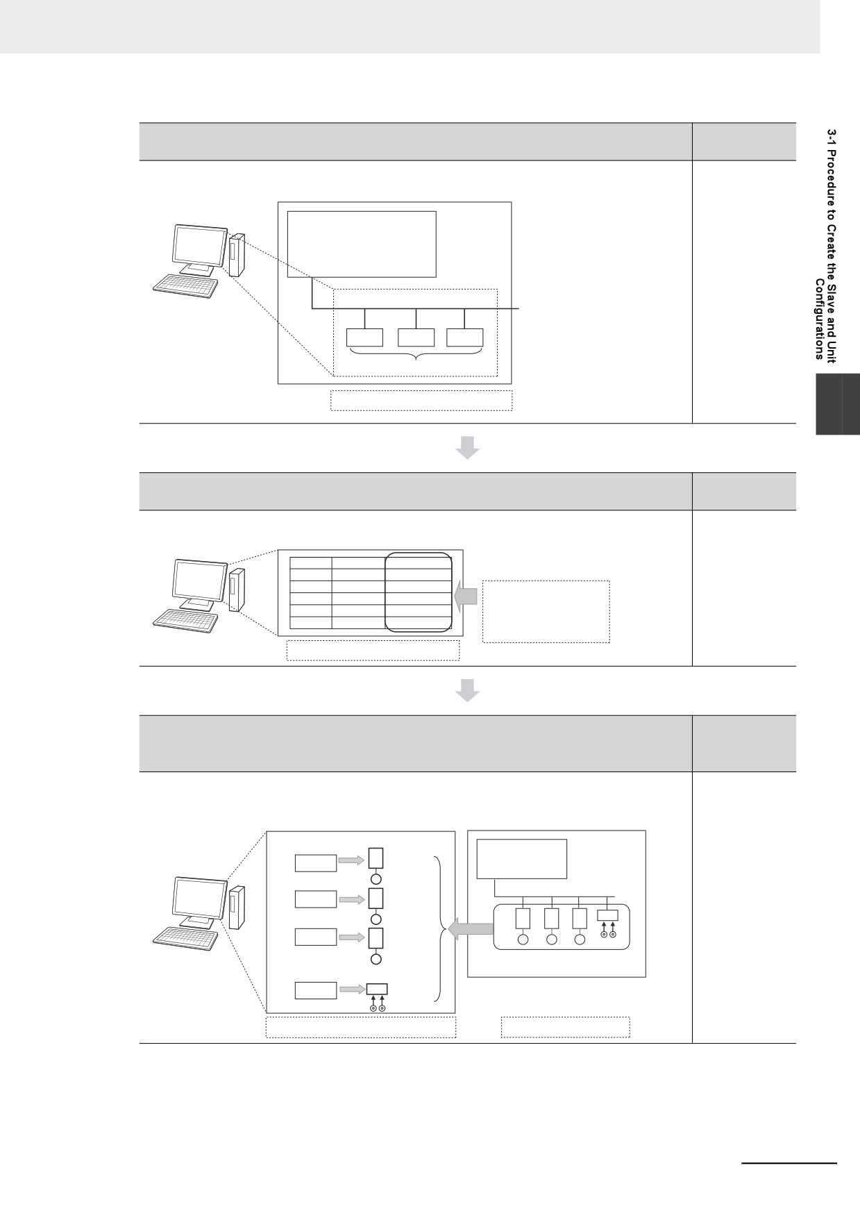
Step 1
Create the EtherCAT Slave Configuration (if EtherCAT is used).
• Create the EtherCAT Slave Configuration.
3-2 Creating
EtherCAT slave configuration
the EtherCAT
Slave Configu-
Sysmac Studio
ration
Controller
EtherCAT
Slave configuration information
Created with the EtherCAT slave configuration settings.
3
Reference
Step 2
Assign device variables to I/O ports.
• Register the device variables.
2-3-1 Types of
Registering the device variables
Variables
Sysmac Studio
Slave/Unit
I/O port
Device variable
3-3 I/O Ports
and Device
Assign a new device
Variables
variable or a variable
from a variable table for
each I/O port.
Created in the I/O Map.
Reference
Step 3
Create the axes and assigning them to the Servo Drive and encoder
input slaves (if motion control is used).
1. Create the axes.
3-5 Creating
2. Assign the axes to the Servo Drive and encoder input slaves in the EtherCAT configuration.
the Axes and
Axis Setup
EtherCAT slave configuration
Assigning
Them to the
Servo Drives
Axes
Assigned.
Servo
A
Controller
Axis variable a
Sysmac Studio
Drives/Encoder
Input Slaves
EtherCAT
Axis variable b
B
A
B
C
D
Axis variable c
C
Servo Drives/encoder input slaves
Encoder input slave
Axis variable d
D
Assigned in the Axis Setup.
From the EtherCAT Configuration Setup
3-3
3 I/O Ports, Slave Configuration, and Unit Configuration
3-2
Creating the EtherCAT Slave
Configuration
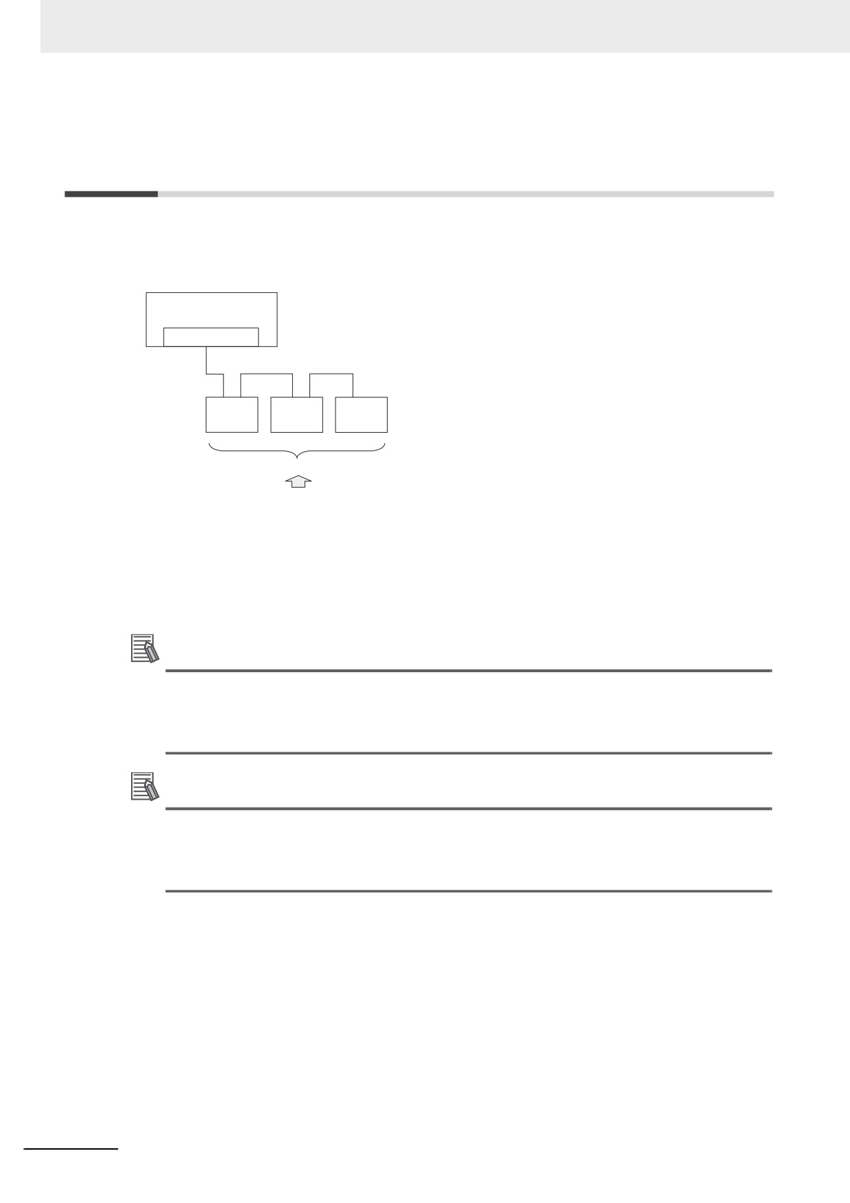
To enable accessing the slaves that are connected to the NY-series Controller, you create a slave con-
figuration on the Sysmac Studio. In the EtherCAT Tab Page of the Sysmac Studio, create the EtherCAT
slave configuration that is detected as “correct” by the NY-series Controller.
Controller
EtherCAT master
EtherCAT
EtherCAT
EtherCAT
EtherCAT
slave
slave
slave
EtherCAT slave configuration
Created with the Sysmac Studio.
The I/O ports are automatically registered for the slaves in the configuration. Later, the user assigns
device variables to the I/O ports. You can specify device variables in the user program to access the
slaves.
Refer to EtherCAT Configuration and Settings in the Sysmac Studio Version 1 Operation Manual (Cat.
No. W504) for specific procedures to create the EtherCAT slave configuration.
Additional Information
If you connect EtherCAT Slave Terminals, create the EtherCAT slave configuration, create the
Slave Terminal configuration, and set the operation settings. Refer to the NX-series EtherCAT
Coupler Unit User’s Manual (Cat. No. W519) for information on the Slave Terminal configuration
and operation settings.
Additional Information
If the EtherCAT slaves are Servo Drives or encoder input slaves, after they are registered in the
EtherCAT slave configuration, Axis Variables are registered automatically by creating the axes.
Refer to 3-5 Creating the Axes and Assigning Them to the Servo Drives/Encoder Input Slaves
for details.
3-4
3 I/O Ports, Slave Configuration, and Unit Configuration
3-3
I/O Ports and Device Variables
This section describes the I/O ports and device variables that you use to access the EtherCAT slaves of
an NY-series Controller.
3-3-1
I/O Ports
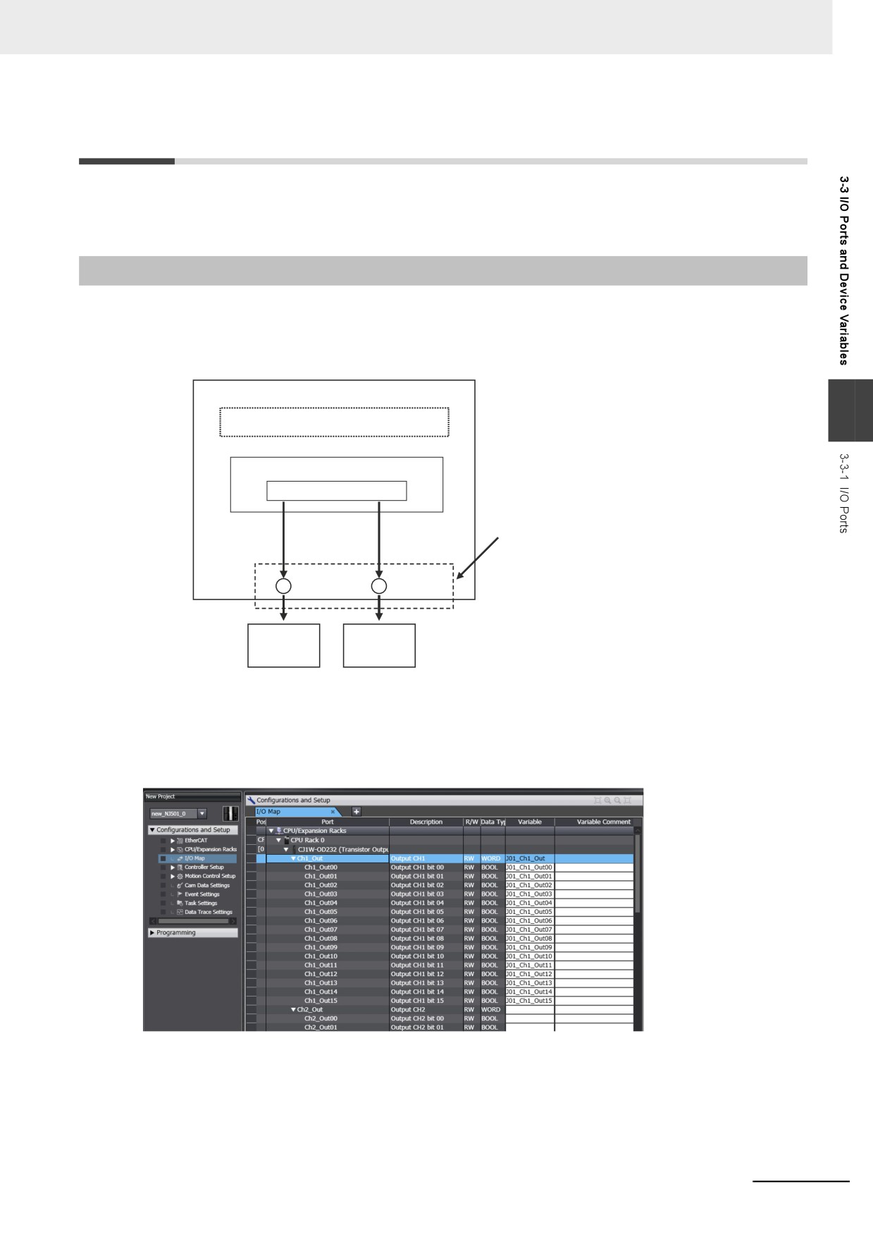
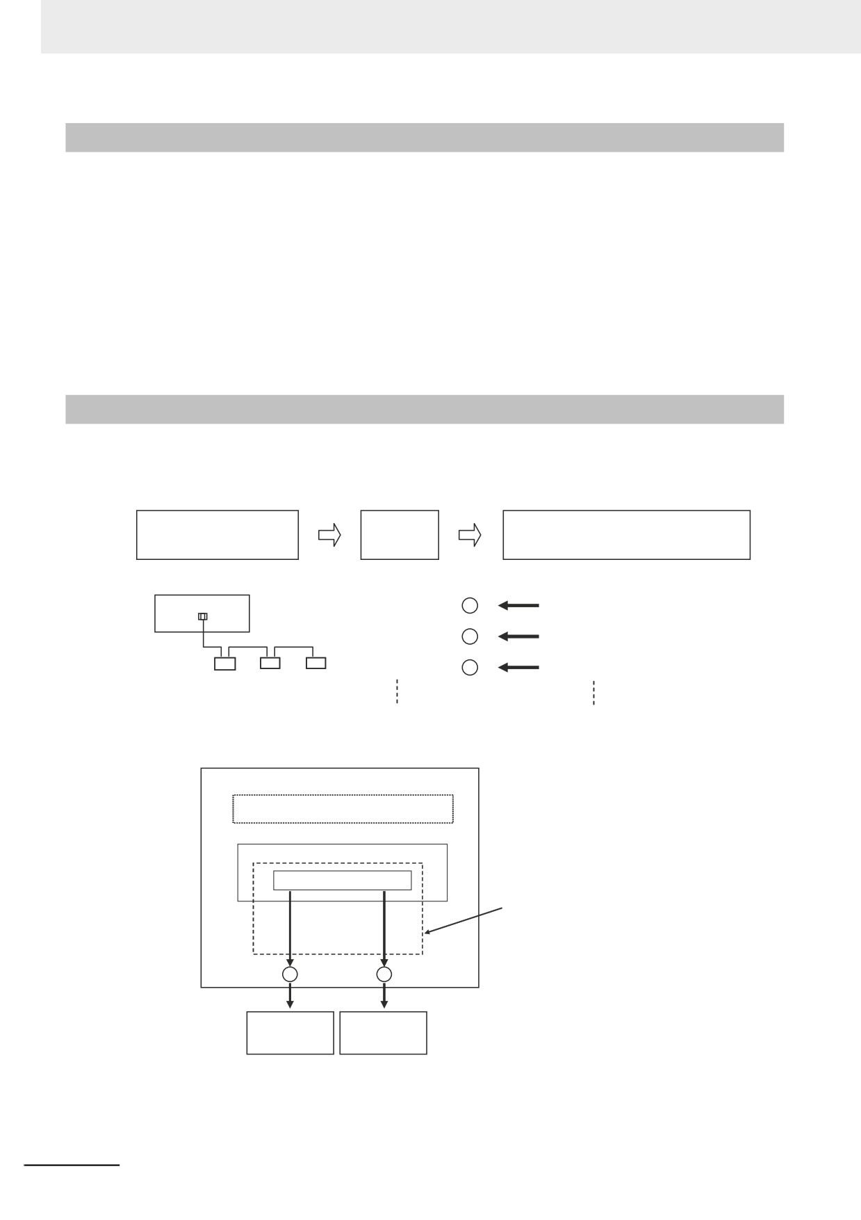
An I/O port is a logical interface that is used by the NY-series Controller to exchange data with external
devices (slaves and Units). I/O ports are automatically created when you create the Slave and Unit
Configurations on the Sysmac Studio. You assign device variables to I/O ports to enable accessing the
slaves and Units from the user program.
NY-series Controller
3
User program (or external communications)
Variables
Device variables
I/O ports are logical interfaces used by
the Controller to exchange data with
external devices.
I/O ports
I/O ports
Outside of the
Controller
EtherCAT
EtherCAT
slaves
slaves
I/O ports are automatically registered in the I/O Map when you create the EtherCAT Slave Configura-
tion or Unit Configuration in the Sysmac Studio, or when you read either of these configurations from
the physical Controller from the Sysmac Studio. You can check the I/O ports that were registered in the
I/O Map of the Sysmac Studio.
I/O Map
3-5
3 I/O Ports, Slave Configuration, and Unit Configuration
3-3-2
I/O Port Names
The I/O port names are registered automatically. The following I/O port name is used when the device
(i.e., Unit or slave) is an EtherCAT slave.
The following I/O port names are used for Remote I/O Terminals that are EtherCAT slave devices.
Example for a 16-point Remote I/O Terminal: Bit00 to Bit15
For other slaves, all or part of the object names that are defined in the EtherCAT object dictionary are
used.
Example for Analog Input Unit: CH0_input16-bit
Examples for the R88D-KN50H-ECT: Position actual value and Digital inputs
3-3-3
Device Variables
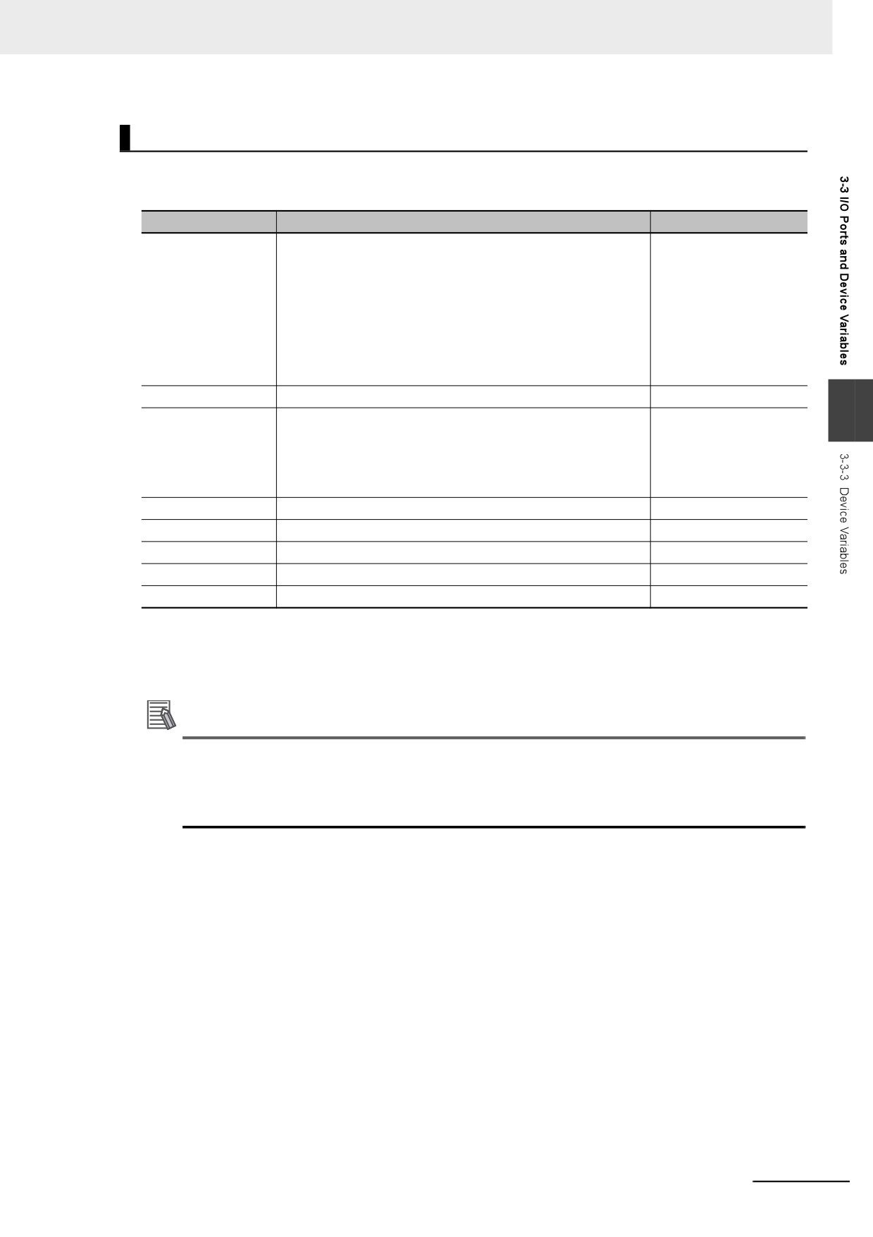
In an NY-series Controller, external devices (slaves and Units) are not assigned to specific memory
addresses in the Controller. Rather, variables are assigned to the I/O ports. These variables are called
device variables.
Slave and Unit Configuration
I/O ports
Variables assigned to I/O ports:
Information created.
created.
Device variables
Slave and Unit Configurations
I/O ports
Device variables
Assigned.
Bit00
E001_Bit00
Bit01
E001_Bit01
Bit02
E001_Bit02
You can specify device variables in the user program or in external communications to access the
devices (slaves or Units).
NY-series Controller
User program (or external communications)
Variables
Device variables
Variables are assigned to I/O ports.
These variables are called device
variables.
I/O ports
I/O ports
Outside of the
General-purpose
General-purpose
Controller
EtherCAT slaves
EtherCAT slaves
Refer to 2-3-1 Types of Variables for the relationship of device variables to other variables.
Refer to the Sysmac Studio Version 1 Operation Manual (Cat. No. W504) for details on registering
device variables with the Sysmac Studio.
3-6
3 I/O Ports, Slave Configuration, and Unit Configuration
Device Variable Attributes
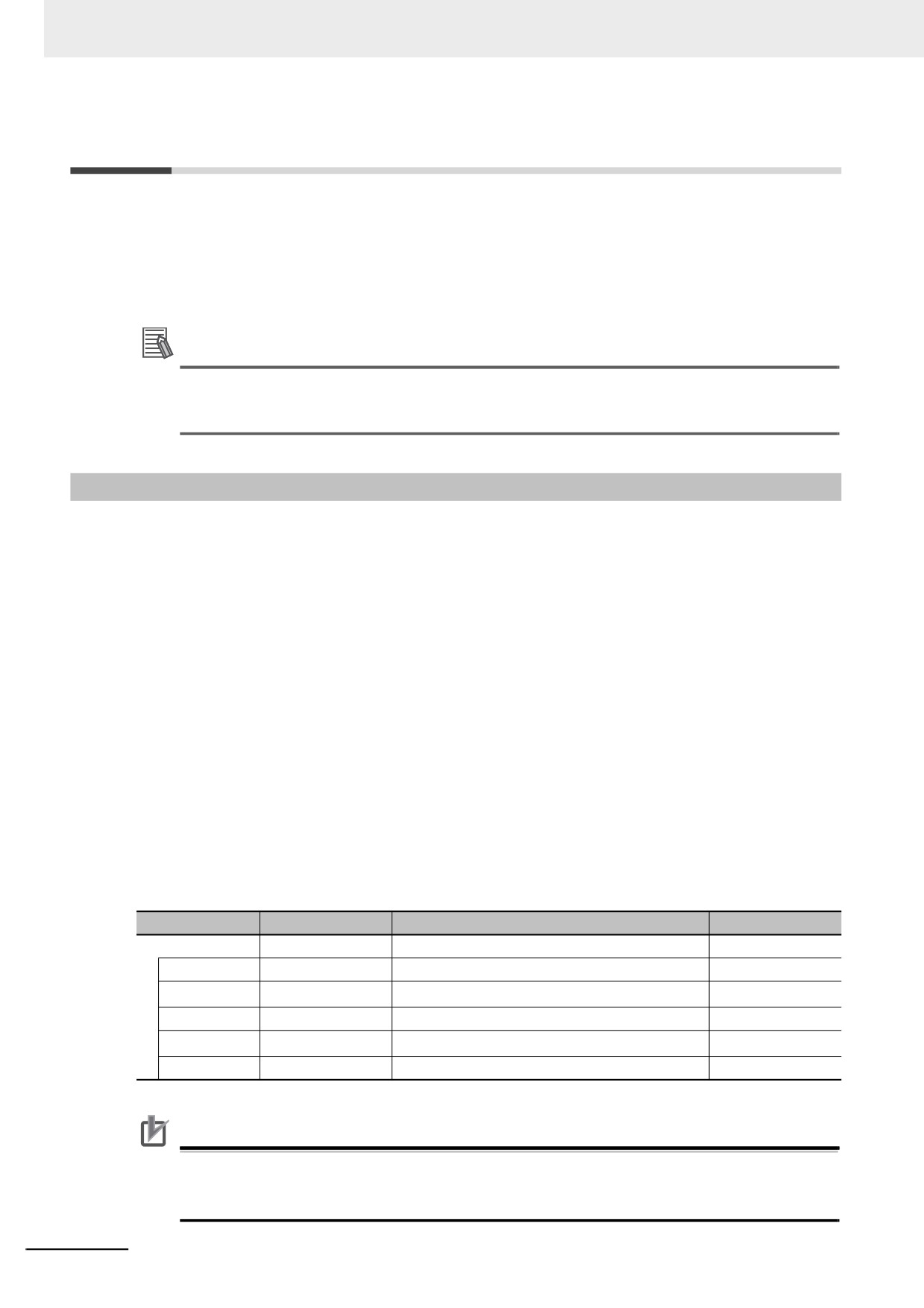
The attributes of the device variables are described in the following table. You can change the settings
of some of the attributes, but not all of them.
Attribute
Setting
Changes to settings
Variable Name
Automatically generated variables: [device_name] +
Allowed.
[I/O_port_name]
For the default device names of EtherCAT slaves, an E fol-
lowed by a sequential number starting from 001.
Refer to 3-3-2 I/O Port Names for more information on I/O port
names.
If entered manually, the variable name is the string you enter.
Data Type
According to the data type of the I/O port.
Allowed.
3
AT Specification
• NX Units connected through an EtherCAT Coupler Unit:
Not allowed.
ECAT://node#[EtherCAT_Coupler_Unit_node_ad-
dress.NX_Unit_number]/[I/O_port_name]
• EtherCAT slaves: ECAT://node#[node_ad-
dress]/[I/O_port_name]
Retain
Device variables for EtherCAT slaves: Not retained.
Not allowed.
Initial Value
None
Allowed.
Constant
None
Allowed.
Network Publish
Do not publish.
Allowed.
Edge
None
Not allowed.
Refer to 6-3-4 Attributes of Variables for the meanings of the attributes.
Additional Information
• You can specify forced refreshing for I/O ports in the I/O Map. You can force real I/O to turn ON
or OFF to check the wiring.
• You can choose the variable table (global variable table or local variable table for one POU) in
which to register a device variable in the I/O Map.
3-7
3 I/O Ports, Slave Configuration, and Unit Configuration
3-4
Allocating Variables to Units
For some instructions, the Units on EtherCAT Slave Terminals are specified by using variables. There-
fore, you must assign variables to the Units in advance. After you assign variables to the Units, the con-
nection locations of the Units are automatically updated in the variables even if you change the
locations. This means that you do not have to assign variables again every time you change the Unit
connection locations.
Additional Information
You can assign variables to EtherCAT slaves other than Slave Terminals. This applies to Ether-
CAT slaves from other manufacturers. The variables are assigned to the EtherCAT slaves in the
same way as they are assigned to EtherCAT Coupler Units and NX Units.
3-4-1
Procedure to Assign Variables to Units
The variables assigned to the Units are not created automatically when you make configuration settings
for an EtherCAT Slave Terminal on the Sysmac Studio. You must make the following settings to assign
the variables to the Units.
1 On the Sysmac Studio, select Configurations and Setup − EtherCAT and make configuration
settings for EtherCAT Slave Terminals.
2 Select Configurations and Setup − I/O Map to display the I/O Map.
The I/O Map is displayed for the Units of the set EtherCAT Slave Terminals.
3 Right-click the model of Unit to which you want to assign variables and select Display Node
Location Port from the menu.
The Node location information port will be added on the I/O Map.
4 Right-click the Node location information and select Create Device Variable.
The variable name will be written automatically to the Variable Field of the Node location
information port.
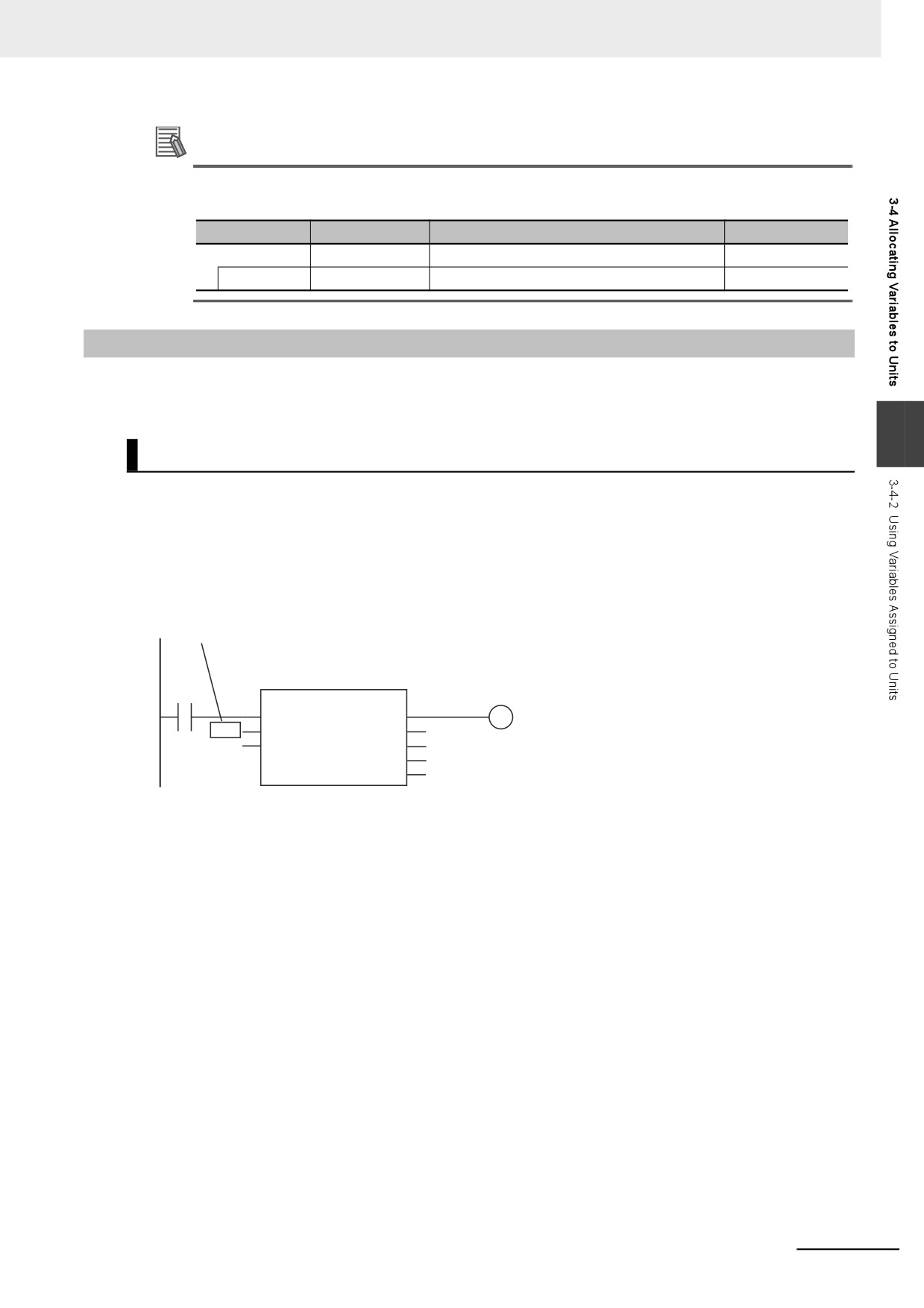
The data type of variables assigned to the Units is _sNXUNIT_ID structure. The details on the _sNX-
UNIT_ID structure data type are given in the following table.
Variable
Name
Meaning
Data type
User specified
Specified Unit
Specified Unit
_sNXUNIT_ID
NodeAdr
Node address
Node address of the EtherCAT Coupler Unit
UINT
IPAdr
IP address*1
IP address of the EtherCAT Coupler Unit
BYTE[5]
UnitNo
Unit number
Unit number of the specified Unit
UDINT
Path
Path*1
Path information to the specified Unit
BYTE[64]
PathLength
Valid path length
Valid path length
USINT
*1
This information is used only inside the Controller. You cannot access or change it.
Precautions for Correct Use
The values of variables assigned to the Units will be set automatically when you register the vari-
ables. Do not change the values of the variables. If you change the value, the Controller may not
perform the intended operation.
3-8
3 I/O Ports, Slave Configuration, and Unit Configuration
Additional Information
The data type of variables assigned to EtherCAT slaves other than Slave Terminals is _sECAT_ID
structure. The details are given in the following table.
Variable
Name
Meaning
Data type
User specified
Specified slave
Specified slave
_sECAT_ID
NodeAdr
Node address
Node address of the EtherCAT Coupler Unit
UINT
3-4-2
Using Variables Assigned to Units
This section describes how to use the variables assigned to the Units in the user program. In any
cases, the variable with the same name as the variable assigned to the Unit on the I/O Map must be
registered in the variable table in advance. The data type of the variable is _sNXUNIT_ID structure.
3
Designating Units
The variables assigned to the Units are passed as parameters to the instructions for which specify the
Units.
Example: Executing the NX_SaveParam Instruction
In the following example, the NX Unit to which the NX1 variable is assigned is specified when the
NX_SaveParam instruction is executed. NX1 is passed to the UnitProxy variable.
Variable assigned to NX Unit
NX_SaveParam_instance
A
NX_SaveParam
B
Execute
Done
NX1
UnitProxy
Busy
UINT#0
TimeOut
Error
ErrorID
ErrorIDEx
3-9
3 I/O Ports, Slave Configuration, and Unit Configuration
Designating Unit Attributes
You can specify members of the variables that you assign to Units to specify some of the Unit attributes.
Example: Executing an Instruction with the Unit Number of an NX Unit
The following programming example reads a data object from an NX Unit if the NX Unit number of the
NX Unit to which the NX1 variable is assigned is 2. The NX1.UnitNo member gives the NX Unit number.
IF (NX1.UnitNo = UINT#2) THEN
NX_ReadObj_instance(Execute:=TRUE, UnitProxy:=NX1, Obj:=S_Obj, ReadDat:=Rdat);
END_IF;
Designating More Than One Unit
To designate more than one Unit, you can specify the elements of an array of the variables that are
assigned to the Units. This allows you to use loop processing to perform the same process for more
than one Unit.
Example: The following programming example changes multiple NX Units to the mode that enables
writing data.
NX0, NX1, and NX2 are the variables that were assigned to the NX Units. The variables are assigned
to the elements of the NXTable[0..2] and then the NX_ChangeWriteMode instruction is executed in
order for each.
• Variable Table
Variable
Data type
NXTable
ARRAY[0..2] OF_sNXUNIT_ID
• ST Program
FOR i:= 0 TO 2 DO
NX_ChangeWriteMode_instance[i](Execute:=FALSE);
END_FOR;
NXTable[0] := NX0;
NXTable[1] := NX1;
NXTable[2] := NX2;
FOR i:= 0 TO 2 DO
NX_ChangeWriteMode_instance[i](Execute:=TRUE, UnitProxy:=NXTable[i]);
END_FOR;
3-10
3 I/O Ports, Slave Configuration, and Unit Configuration
3-5
Creating the Axes and Assigning
Them to the Servo Drives/Encoder
Input Slaves
This section describes how to create axes in the NY-series Controller and how to assign the axes to the
Servo Drive and encoder input slaves.
3-5-1
Introduction
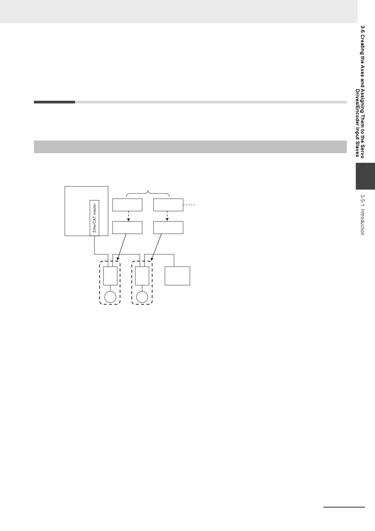
When you use the Motion Control Function Module for operation with EtherCAT Servo Drive or encoder
input slaves, create axes in the Sysmac Studio and define them as EtherCAT Servo drives or encoder
input slaves. At a result, Axis Variables are automatically created as system-defined variables.
3
Controlled by the Motion Control Function Module.
Controller
Axis A
Axis B
Functional units within the
Motion Control Function Module
Created.
Created.
Axis variable A
Axis variable B
Assigned.
Assigned.
EtherCAT
EtherCAT
slave
Servo Drive/encoder
Servo Drive/encoder
input slave
input slave
You can specify an Axis Variable in a motion control instruction in the user program to easily access
and perform operations with Servo Drive and encoder input slaves.
3-11
3 I/O Ports, Slave Configuration, and Unit Configuration
3-5-2
Axis Variables and Axes Group Variables
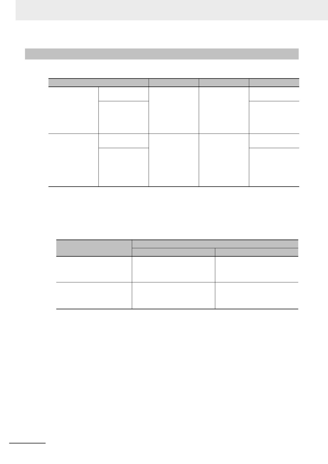
The following table lists the types of Axis Variables and Axes Group Variables.
Type of variable
Application
Device to access
Creation method
Axis Variables
System-defined axis
An Axis Variable is
The EtherCAT slave
Provided by the sys-
variables
used to control a sin-
(Servo Drive or
tem.
gle axis.
encoder input slave)
Axis Variables auto-
You must create an
that is assigned to
matically created
axis with Sysmac
the axis
when axes are cre-
Studio and assign
ated with the Sys-
the device to the
mac Studio
axis.
Axes Group Vari-
System-defined
An Axes Group Vari-
The EtherCAT
Provided by the sys-
ables
axes group variables
able is used for
slaves (Servo Drive
tem.
multi-axes coordi-
or encoder input
Axes Group Vari-
You must create an
nated control.
slaves) that are
ables automatically
axes group with the
assigned to the axes
created when axes
Sysmac Studio.
group
groups are created
with the Sysmac
Studio
Refer to the NY-series Motion Control Instructions Reference Manual (Cat. No. W561) for details on
Axis Variables and Axes Group Variables.
Specifying Axis and Axes Group Variables
The variables can be specified with variable names that are created with the Sysmac Studio or with
system-defined variable names.
Names
Type
Axis Variables
Axes Group Variables
Variable names created with the Sys-
MC_Axis*** (“***” is assigned in ascend-
MC_Group*** (“***” is assigned in
mac Studio
ing order from 000 in the order the vari-
ascending order from 000 in the order
ables are created.)
the variables are created.)
You can change the names as required.
You can change the names as required.
System-defined variable names
_MC_AX[***]
_MC_GRP[***]
(The array element numbers are
(The array element numbers are
assigned in ascending order from 0 in
assigned in ascending order from 0 in
the order the variables are created.)
the order the variables are created.)
Application
There are two ways to use Axis Variables and Axes Group Variables.
1) Specifying Axes and Axes Groups in Motion Control Instructions:
If you specify an axis or axes group for an I/O variable for a motion control instruction, you
can perform operations for the OMRON Servo Drive or encoder input slave.
2) Monitoring Axis Variable Members:
You can use instructions to monitor the actual position, error information, or other information
on the Servo Drive and encoder input slaves.
3-12
3 I/O Ports, Slave Configuration, and Unit Configuration
Additional Information
Details on Axis Variables
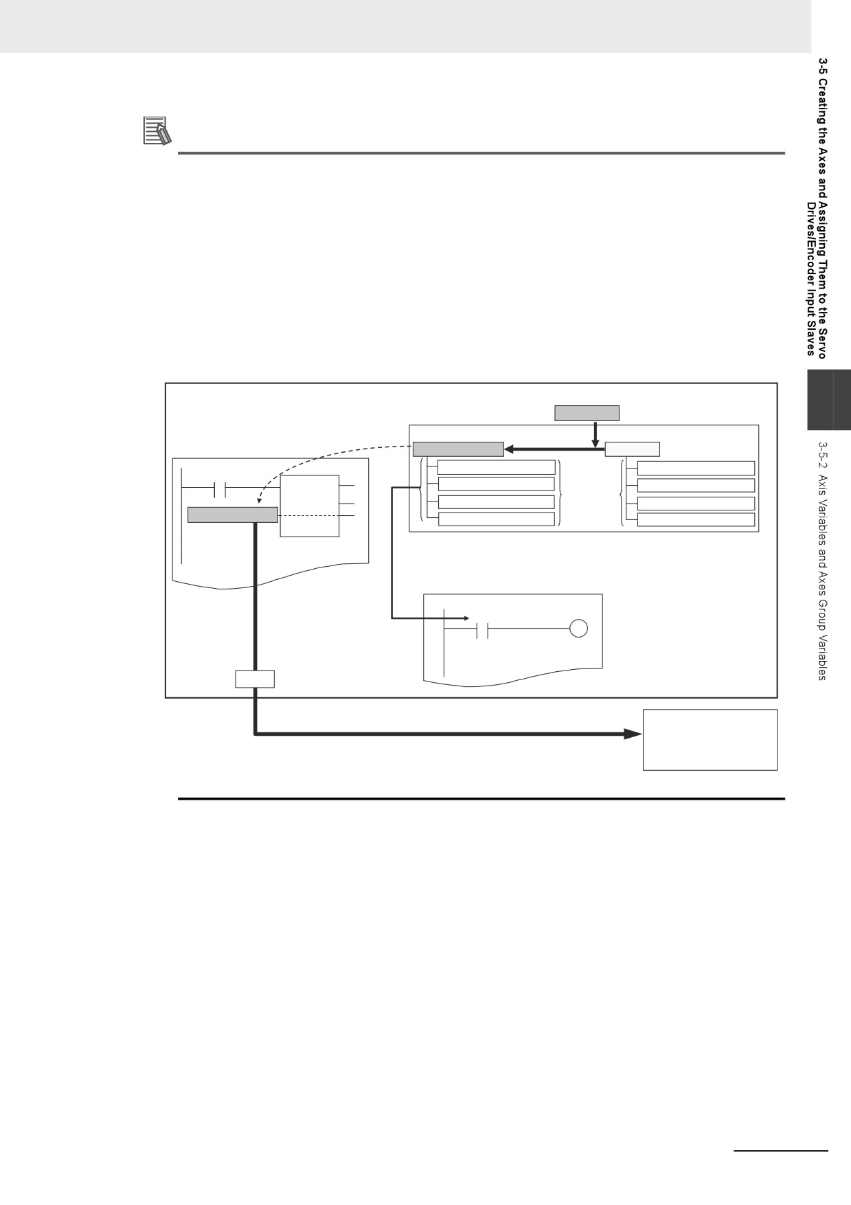
1. Assume that you create an axis with an axis name of A on the Sysmac Studio. An Axis Vari-
able with a variable name of A is created automatically based on the system-defined axis vari-
able. The Axis Variable consists of Axis Basic Settings, Unit Conversion Settings, I/O, operating
status, current values, error status, and warning status.
2. You specify the axis variable name A for the in-out variable of a motion control instruction.
With the axis variable name, you can access the OMRON Servo Drive or encoder input slave, or
supported Servo Drive or encoder input slave from another company and perform operations for
it.
3. You can specify the Axis Variable to use instructions as required to monitor the actual position,
error information, or other information on the Servo Drive or encoder input slave.
NY-series Controller
3
2. An axis or axes group is specified for a
1. The
axis MC_Axis***
is created on the Sysmac Studio.
Global Variable Table
motion control instruction.
Axis Variable
An Axis Variable is made
System-defined Variable
Only the axis variable name
under a different name.
is specified.
Axis variable name: MC_Axis***
_MC_AX[]
Axis basic settings and unit conversions
Axis basic settings and unit conversions
Motion
I/O
The data types
I/O
control
cannot be
Operating status and current values
Operating status and current values
instruction
changed.
Axis variable name: MC_Axis***
Error/warning status
Error/warning status
3. You can monitor the members of the axis variable with instructions.
The values can be read and written with instructions.
A.××
Value of a member of
the Axis Variable
Assigned
axis
OMRON Servo Drives or
Control operations
EtherCAT
encoder input slaves, or
supported Servo Drives or
encoder input slaves from
other companies
3-13
3 I/O Ports, Slave Configuration, and Unit Configuration
3-5-3
Creating and Using Axes and Axis Variables
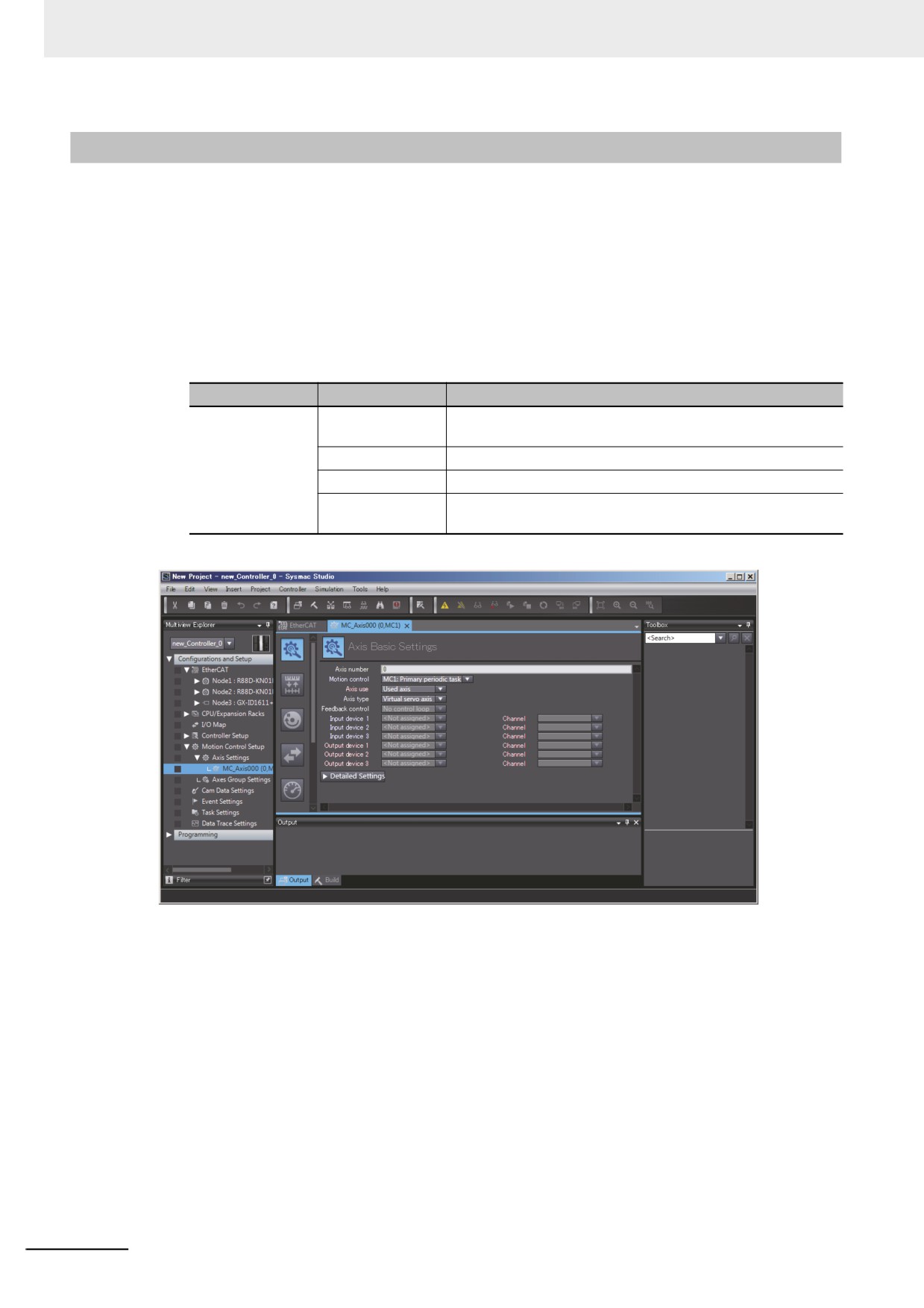
You can create and use axes and Axis Variables as described below.
1 Right-click Axis Settings under Configurations and Setup − Motion Control Setup in the
Multiview Explorer and select Add − Axis Settings from the menu.
If necessary, you can change the axis variable names from the default names of MC_Axis***.
(“***” is incremented from 000 in the order that the axis variables are created.)
2 Assign the axes that you created to Servo Drives or encoder input slaves in the EtherCAT Slave
Configuration of the Sysmac Studio.
Set the Axis Basic Settings from the Sysmac Studio.
Classification
Parameter name
Setting
Axis Basic
Axis Number
Axis numbers are automatically set in the order that the axes
Settings
are created.
Axis Use
Select Used axis.
Axis Type
Select a servo axis or encoder axis.
Input Device/
Specify the node address of the EtherCAT slave that is
Output Device
assigned to the axis.
3 Use the Sysmac Studio to specify the settings required for Test Mode operation (Unit Conver-
sion, Count Mode, Limits, etc.) and the settings required for actual system operation. Then
transfer the settings to the Controller with the project.
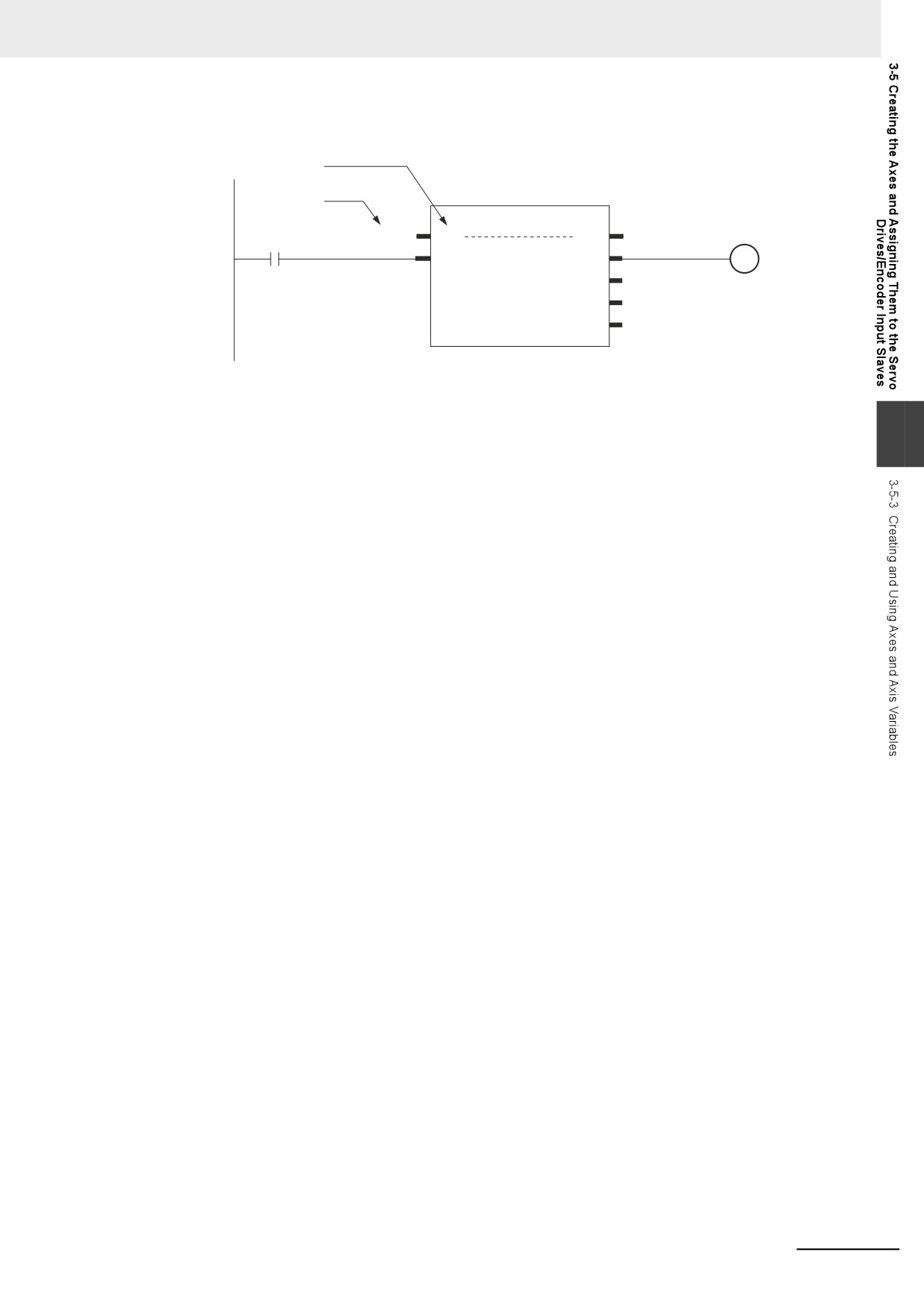
4 In the user program, an axis variable name is specified for the in-out variable Axis in motion
control instructions.
For the axis variable name, specify the axis name (axis variable name) that was specified in the
Motion Control Setup or a system-defined variable. You can execute motion control for the
assigned Servo Drive or encoder input slave. An example that specifies the axis variable name
MyAxis1 is shown below.
3-14
3 I/O Ports, Slave Configuration, and Unit Configuration
Example:
In-out variable Axis
MyAxis1On
Specify an axis
variable name.
MC_Power
MyAxis1
Axis
Axis
MyAxis1
MyAxis1OnStatus
Enable
Status
ServoOn
Busy
MyAxis1OnBusy
Error
MyAxis1OnError
ErrorID
MyAxis1OnErrorID
Refer to 3-5-2 Axis Variables and Axes Group Variables for information on Axis Variables.
3
3-15
Controller Setup
This section describes the initial settings of the function modules.
4
4-1
Overview of the Controller Setup
4-2
4-2
Initial Settings for the PLC Function Module
4-4
4-2-1
Introduction
4-4
4-2-2
Controller Setup
4-4
4-2-3
Task Settings
4-7
4-3
Initial Settings for the Motion Control Function Module
4-12
4-3-1
Introduction
4-12
4-3-2
Setting Methods
4-13
4-4
Initial Settings for the EtherCAT Master Function Module
4-14
4-5
Initial Settings for the EtherNet/IP Function Module
4-15
4-1
4 Controller Setup
4-1
Overview of the Controller Setup
This section provides an overview of the Controller Setup.
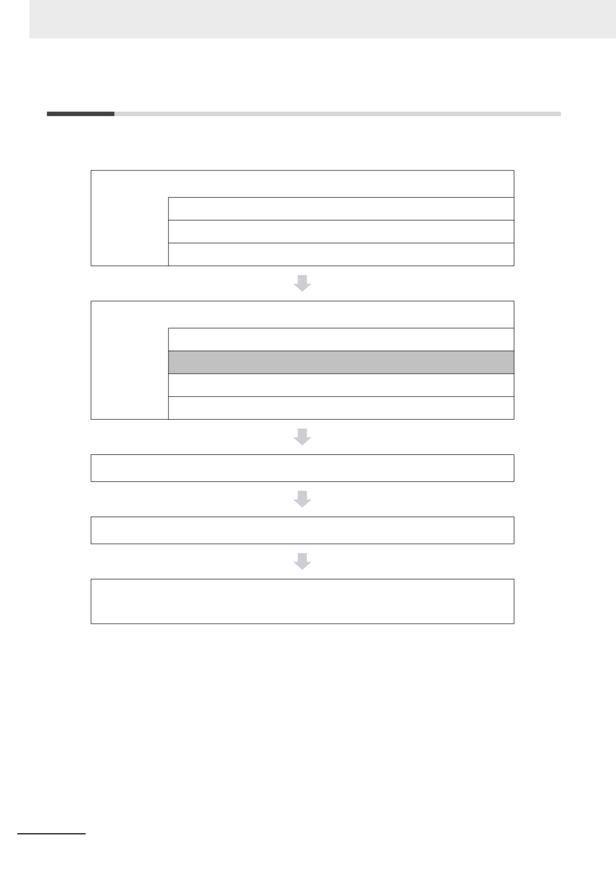
The shaded steps in the overall procedure that is shown below are related to the Controller Setup.
Step 1. Software Design
Step 1-1 Designing I/O and Processing
Step 1-2 Designing Tasks
Step 1-3 Designing Programs
Step 2. Software Setups and Programming
Step 2-1 Slave and Unit Configurations
Step 2-2 Controller Setup
Step 2-3 Programming
Step 2-4 Offline Debugging
Step 3. Mounting and Setting Hardware
Step 4. Wiring
Step 5. Checking Operation and Starting Operation on the
Actual System
Refer to 1-4 Overall Operating Procedure for the NY-series Controller for details.
4-2
4 Controller Setup
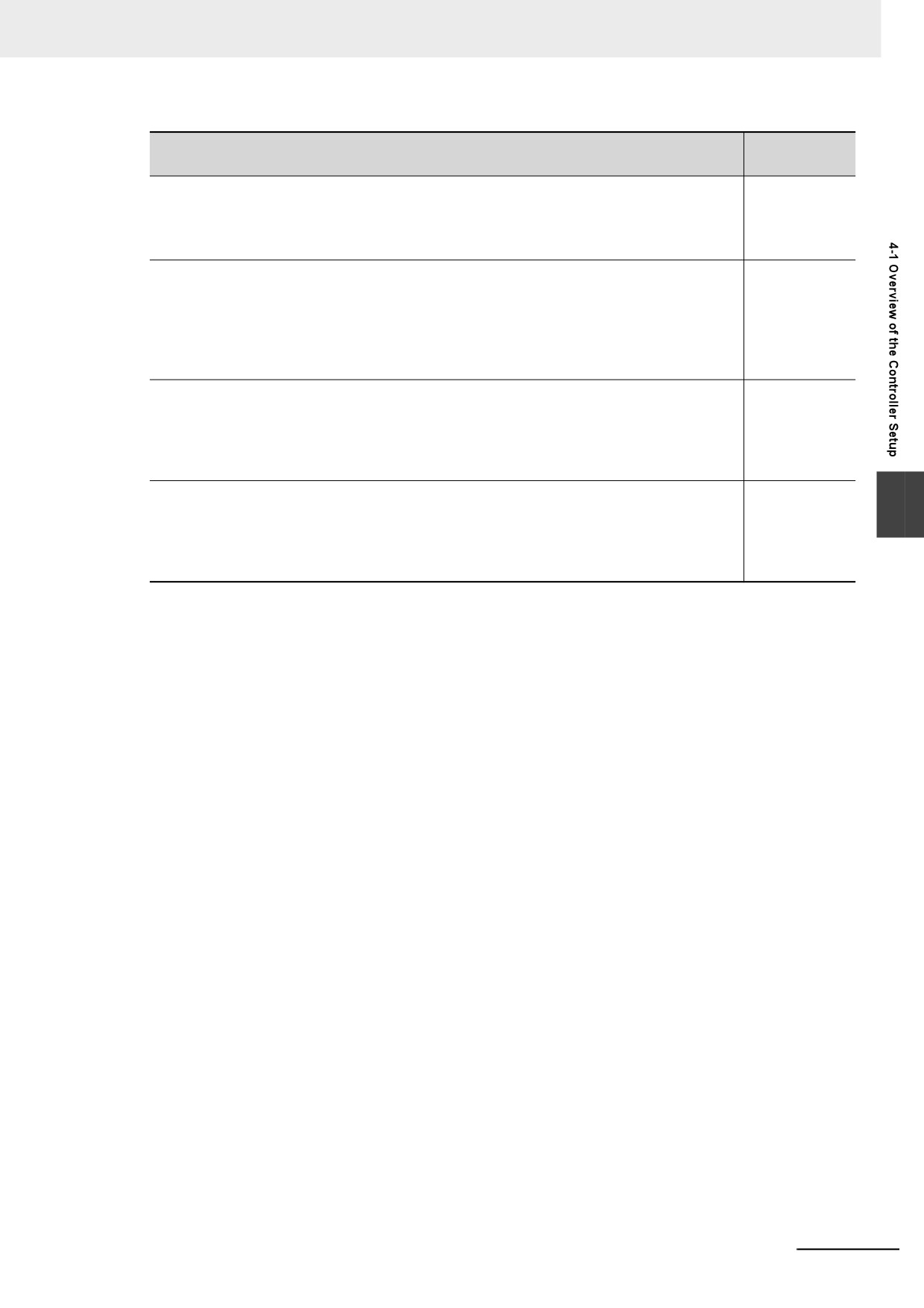
Controller Setup
Reference
z Initial Settings Related to the PLC Function Module:
4-2 Initial Set-
tings for the
Controller Setup: Startup Mode, Write Protection, System Service Moni-
PLC Function
toring Settings, and other settings
Module
z Initial Settings for the Motion Control Function Module:
4-3 Initial Set-
tings for the
• Axis Parameters: Motion control parameters for single-axis operation
Motion Control
• Axes Group Parameters: Motion control parameters for multi-axes coor-
Function Mod-
dinated operation
ule
• Cam data: Phase and displacement setting tables for cam motions
z Initial Settings for the EtherCAT Master Function Module:
4-4 Initial Set-
tings for the
EtherCAT Master Parameters in the EtherCAT Configuration:
EtherCAT Mas-
Parameter settings for the EtherCAT master process data communications
ter Function
cycle, and other settings
Module
z Initial Settings for the EtherNet/IP Function Module:
4-5 Initial Set-
4
tings for the
Ethernet Port Setup: EtherNet/IP Port TCP/IP Settings, Ethernet Settings,
EtherNet/IP
and other settings
Function Mod-
ule
4-3
4 Controller Setup
4-2
Initial Settings for the PLC Function
Module
This section describes the initial settings that are required for the PLC Function Module.
4-2-1
Introduction
The initial settings for the PLC Function Module are listed below.
• Controller Setup
• Task Settings
Select Configurations and Setup − Controller Setup and Configurations and Setup − Task Set-
tings on the Sysmac Studio to make these settings.
4-2-2
Controller Setup
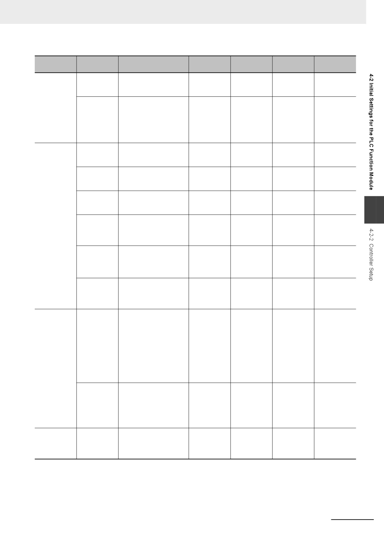
Operation Settings Tab Page
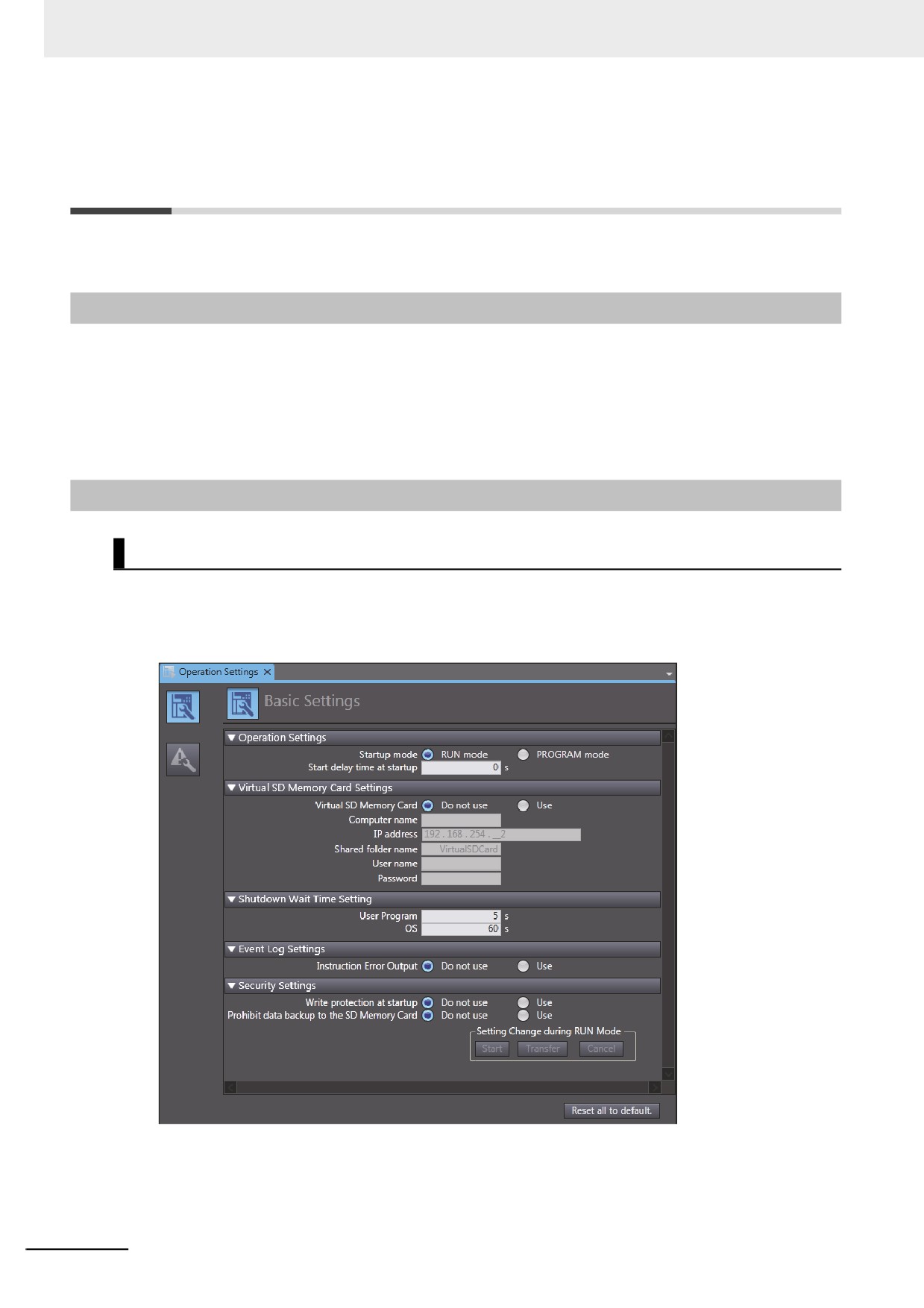
z Basic Settings
The Operation Settings are for functions supported by the Controller, such as the definitions of oper-
ations when the power is turned ON or when the operating mode changes.
4-4
4 Controller Setup
Setting
Update tim-
Changes in
Parameter
Description
Set value
Default
group
ing
RUN mode
Operation
Startup Mode
Sets the CPU Unit’s
RUN or PRO-
RUN mode
When down-
Not allowed.
Settings
operating mode at
GRAM mode
loaded to
startup.
Controller
Start delay
Sets the time to wait for
0 to 10 s
0 s
When down-
Not allowed.
time at
an NS-series PT to per-
loaded to
startup*1
form the tag verifications
Controller
with priority during
startup after the power
supply is turned ON.*2
Virtual SD
Virtual SD
Sets whether to use the
Use.
Disabled.
When down-
Not allowed.
Memory Card
Memory Card
shared folder as a Vir-
loaded to
Do not use.
Settings
tual SD Memory Card.
Controller
Computer
Sets the computer name
Text string*3
None
When down-
Not allowed.
name
on Windows.
loaded to
Controller
IP address
Sets the IP address of an
IPv4*4
192.168.254.2
When down-
Not allowed.
internal port in Windows.
loaded to
Controller
4
Shared folder
Sets a name of the
Text string*5
VirtualSDCard
When down-
Not allowed.
name
shared folder that is used
loaded to
as a Virtual SD Memory
Controller
Card.
User name
Sets a shared user name
Text string*7
None
When down-
Not allowed.
of the shared folder that
loaded to
is used as a Virtual SD
Controller
Memory Card.*6
Password
Sets a password of the
Text string*8
None
When down-
Not allowed.
shared user that is used
loaded to
as a Virtual SD Memory
Controller
Card.
Shutdown
User program
Sets the time to wait
1 to 30 s
5 s
When down-
Not allowed.
Wait Time
when the signal is ON
loaded to
Setting
from a UPS which indi-
Controller
cates a power interrup-
tion detection, or when a
shutdown command is
accepted by pressing the
power supply button until
the Controller starts the
shutdown.
OS
Sets the time to wait
30 to 300 s
60 s
When down-
Not allowed.
when the Controller
loaded to
sends the shutdown com-
Controller
mand to Windows until
the shutdown completion
is detected in Windows.
Event Log
Instruction
Sets whether to output
Do not use.
Do not use.
When down-
Not allowed.
Settings
Error Output
events to an event log
loaded to
Use.
when instruction errors
Controller
occur.
4-5
4 Controller Setup
Setting
Update tim-
Changes in
Parameter
Description
Set value
Default
group
ing
RUN mode
Security Set-
Write Protec-
Sets whether to automat-
Do not use.
Do not use.
When power
Allowed.
ting
tion at Startup
ically enable or disable
is turned ON
Use.
write protection when
you turn ON the power
supply to the Controller.
Prohibit data
Sets whether to enable
Do not use.
Do not use.
When down-
Allowed.
backup to the
or disable SD Memory
loaded to
Use.
SD Memory
Card backups.
Controller
Card*9
*1
This setting is enabled when an NS-series PT is connected to the built-in EtherNet/IP port on the Controller, and the
power supplies for these devices are turned ON simultaneously.
*2
The processing time for verifying tags of an NS-series PT can be reduced with this setting. Set the value to 10 if you want
to give priority to the tag verifications. Otherwise, set the value to 0.
If you set the value to 10, after the power supply is turned ON, the Controller gives priority to the tag verifications of the
NS-series PT for approximately 10 seconds during startup before the Controller changes the startup state to the normal
operation state. The time to complete the tag verifications can be reduced by performing a part of processing of the tag
verifications with priority during startup.
If you specify the value between 1 and 10, the time until the Controller changes the state to the normal operation state is
increased because the Controller gives priority to the tag verifications for the specified time regardless of whether an NS-
series PT is used. Set the value to 0 if an NS-series PT is not connected, or if you do not turn ON the power supplies for
the NS-series PT and the Controller simultaneously.
*3
The usable characters are 0 to 9, A to Z, and a to z. The number of characters is 1 to 15 (not including NULL). The text is
not case sensitive.
*4
You cannot set the following IP addresses.
IP addresses start with 127 (decimal)
Class-D IP addresses (224.0.0.0 to 239.255.255.255)
Class-E IP addresses (240.0.0.0 to 255.255.255.255)
*5
The usable characters are 0 to 9, A to Z, and a to z. The number of characters is 1 to 32 (not including NULL). The text is
not case sensitive.
*6
Use <Domain name>\<User name> when you specify the domain. You can omit specifying the domain name if the user
name in the domain and one in the local are not same.
*7
The usable characters are 0 to 9, A to Z, and a to z, as well as single-byte code (` ~ ! # $ ^ & ( ) _ - { } \ '). The number of
characters is 1 to 274 (not including NULL). The text is not case sensitive.
*8
The usable characters are 0 to 9, A to Z, and a to z, as well as single-byte code (` ~ ! @ # $ % ^ & * ( ) _ - + = { } [ ] \ | : ; "
'
< > . ? /). The number of characters is 8 to 32 (not including NULL). The text is not case sensitive.
*9
A Virtual SD Memory Card is applicable in the NY-series Controller.
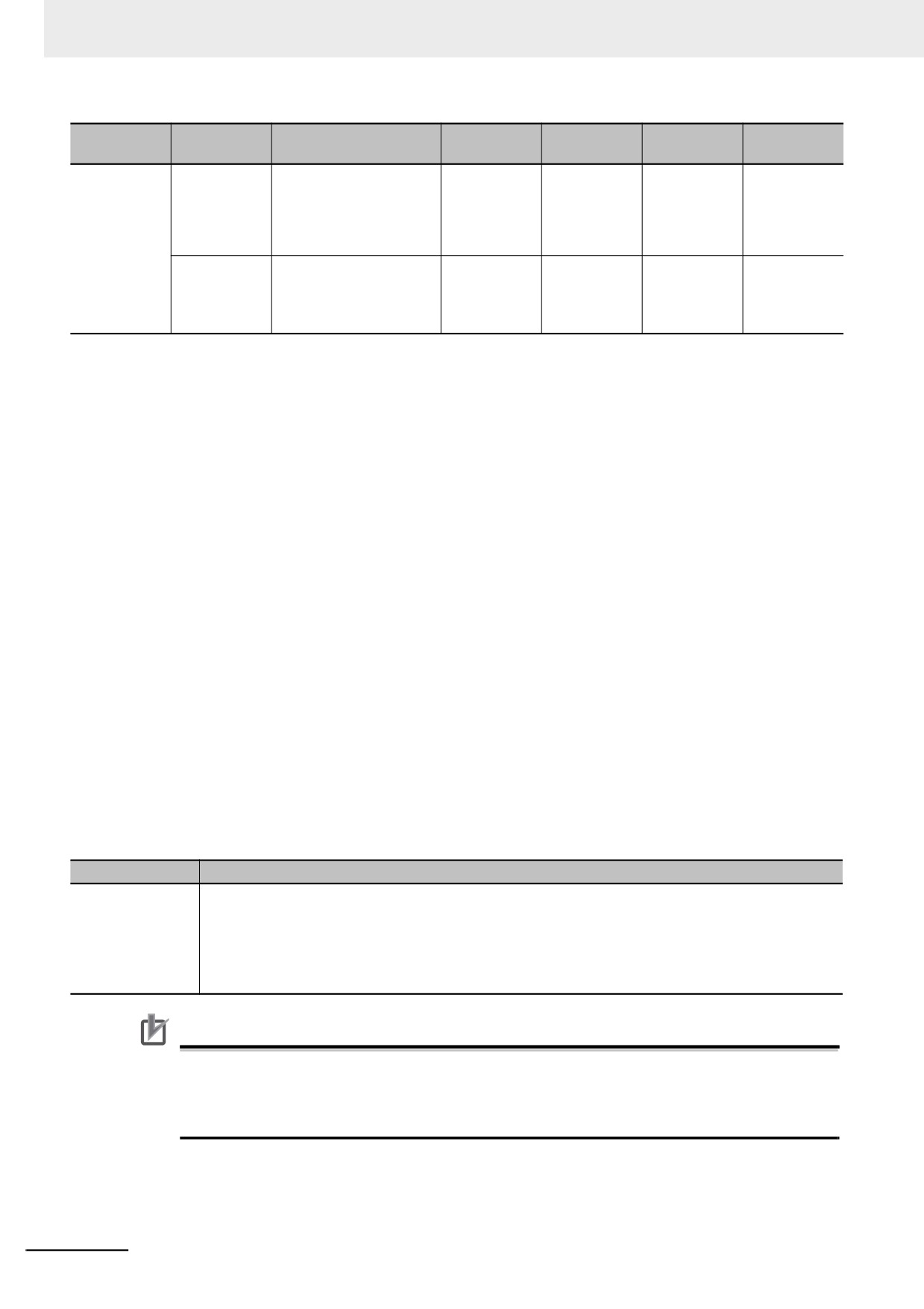
Operation item
Description
Setting Change
You can change the set values of parameters that can be changed during RUN mode.
during RUN Mode
Refer to the Sysmac Studio Version 1 Operation Manual (Cat. No. W504) for the operations.
Start:
Enables writing set values.
Transfer:
Transfers set values to the Controller. The set values are overwritten.
Cancel:
Prohibits writing set values.
Precautions for Correct Use
If Use is selected for Event Log Settings − Instruction Error Output, an instruction error is
output each time an error occurs when an instruction with an error is executed repetitively. This
may cause the event log to exceed the maximum number of events. If this occurs, older events
are overwritten.
4-6
4 Controller Setup
4-2-3
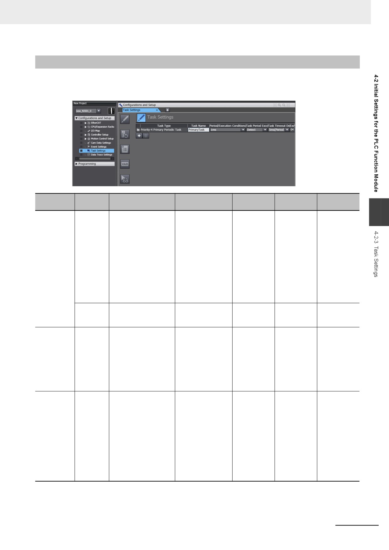
Task Settings
z Task Settings
The Task Settings are used to add and set up tasks.
Setting
Update
Changes in
Parameter
Description
Set value
Default
group
timing
RUN mode
4
Task Type
Sets the task type.
Primary periodic
Primary peri-
When down-
Not allowed.
task
odic task
loaded to
Controller
Priority-16 periodic
task
Priority-17 periodic
task
Priority-18 periodic
task
Priority-8 event task
Priority-48 event
task
Execution
Sets the task execution
Automatically set
Primary peri-
When down-
Not allowed.
Priority
priority.
according to the
odic task: 4
loaded to
task type.
Controller
Task Name
Sets the task name.
Text string
Primary peri-
When down-
Not allowed.
odic task: Pri-
loaded to
maryTask
Controller
Periodic
tasks: Period-
icTask0
Event tasks:
EventTask0
Period/Exe-
Sets the task period.
Primary periodic
Primary
When down-
Not allowed.
cution Con-
task:
periodic task:
loaded to
ditions
500 μs to 8 ms (in
1 ms
Controller
250-μs increments)
Periodic
Periodic tasks:
tasks:
1 ms to 100 ms (in
10 ms (Prior-
250-μs increments)
ity 16, 17, and
Event tasks:
18)
Executed with an
Event tasks:
instruction or when
Execution
a variable expres-
with an
sion is satisfied.
instruction
4-7

4 Controller Setup
Setting
Update
Changes in
Parameter
Description
Set value
Default
group
timing
RUN mode
Task Period
Sets whether to detect
• Detect. (Minor
Primary peri-
When down-
Not allowed.
Exceeded
an error when the task
fault level Con-
odic task and
loaded to
Detection
period is exceeded.
troller error gen-
periodic
Controller
erated.)
tasks: Detect
• Do not detect.
Event tasks:
(Store an obser-
Do not detect
vation level log
(cannot be
record.)
changed).
Task Time-
Sets the task execution
Primary periodic
Primary peri-
When down-
Not allowed.
out Detec-
timeout time. A Task
task and periodic
odic task and
loaded to
tion Time
Execution Timeout
tasks: Task period ×
periodic
Controller
occurs when the time-
1 to Task period × 5
tasks: Task
out time is exceeded.
period × 5
Event tasks: Execu-
tion priority of 8: 1
Event tasks:
to 500 ms
Execution pri-
ority of 8: 200
Execution priority of
ms
48: 1 ms to 10 s
Execution pri-
ority of 48: 1 s
Variable
Sets the percentage of
Primary periodic
3%
When down-
Not allowed.
Access Time
the task period to
task and periodic
loaded to
[%]
assign to variable
tasks: 1% to 50%
Controller
access from outside
Event tasks: None
the Controller.
4-8
4 Controller Setup
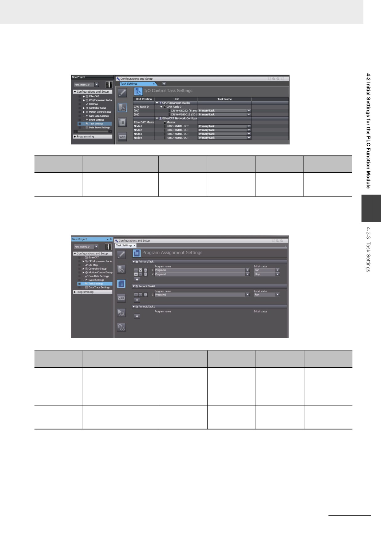
z I/O Control Task Settings
The I/O Control Task Settings are used to set the timing of refresh execution of inputs and outputs.
Changes in
Parameter
Description
Set value
Default
Update timing
RUN mode
Task Name
Sets the task to use to
PrimaryTask
PrimaryTask
When down-
Not allowed.
refresh the specified Units
loaded to Con-
or slaves.
troller
z Program Assignment Settings
4
The Program Assignments Settings are used to assign the programs to tasks, set the program exe-
cution order, and set the operation of the programs at the start of operation.
Changes in
Parameter
Description
Set value
Default
Update timing
RUN mode
Program Execu-
Assigns the programs to the
Assign the pro-
Program0
When down-
Not allowed.
tion Order
specified tasks and sets the
grams in the
loaded to Con-
order of program execution
order to execute
troller
within the tasks.
them from top to
bottom.
Initial Status of
Set whether to run the pro-
Run
Run
When down-
Not allowed.
gram at the start of opera-
loaded to Con-
Program
Stop
tion.
troller
4-9
4 Controller Setup
Precautions for Correct Use
• A program that contains the device variables used to access slaves and Units must be
assigned to the same task as the one to which the slaves and Units that are set in the I/O Con-
trol Task Settings are assigned. A building error will occur if you assign the program to other
tasks.
• The default task set in the I/O Control Task Settings is the primary periodic task. If you want to
assign the program to a task other than the primary periodic task, change the setting in the I/O
Control Task Settings in advance to prevent a building error.
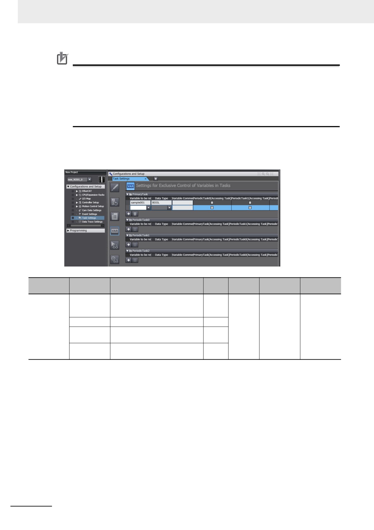
z Settings for Exclusive Control of Variables in Tasks
The Settings for Exclusive Control of Variables in Tasks are used to set the tasks that refresh speci-
fied global variables and the tasks that access specified global variables.
Set
Update tim-
Changes in
Item
Parameter
Description
Default
value
ing
RUN mode
Each Task
Variables to
Sets the variables to refresh in the
None
When down-
Not allowed.
be refreshed
primary periodic task or periodic
loaded to
task.
Controller
Data Type
Sets the data type of variable.
None
Variable Com-
Sets a comment for the variable.
None
ment
Accessing
Sets the tasks that access the vari-
Task
able.
4-10
4 Controller Setup
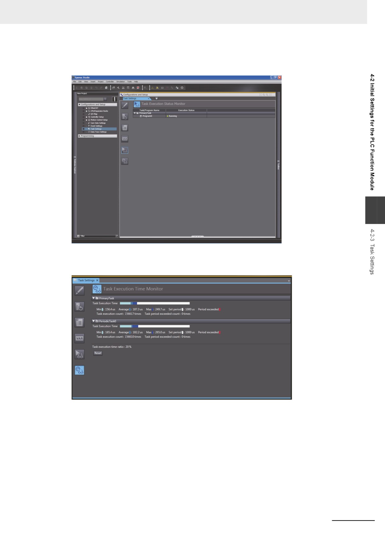
z Task Execution Status Monitor
The Task Execution Status Monitor displays the execution status of the programs.
4
z Task Execution Time Monitor
The Task Execution Time Monitor displays the execution times of the tasks.
4-11
4 Controller Setup
4-3
Initial Settings for the Motion Control
Function Module
This section describes the initial settings that are required for the MC Function Module.
4-3-1
Introduction
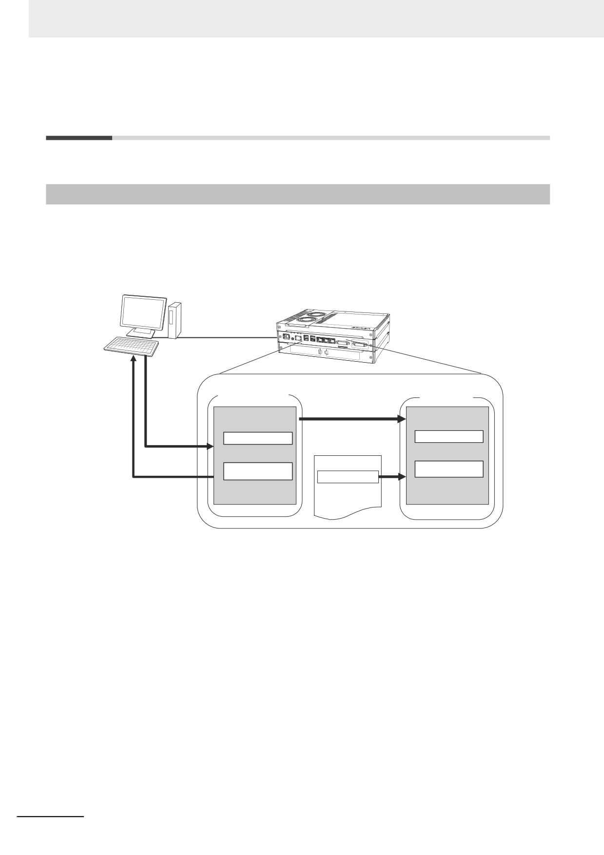
The initial settings for the Motion Control Function Module are called motion control parameters. Motion
control parameters include the following parameters.
• Axis Parameters: Settings for single-axis control
• Axes Group Parameters: Settings for multi-axes coordinated control
Sysmac Studio
Set the parameters in the
Controller
Motion Control Setup.
Motion control
parameters
Built-in non-vola-
tile memory
When power is turned ON
Main memory
When downloaded.
Read and check
Download.
Axis Parameter Settings
data.
Axis Parameter Settings
User program
Upload.
Axes group
Axes Group
Parameter Settings
parameter settings
MC_Write instruction
Temporarily changes
some parameters.
4-12
4 Controller Setup
4-3-2
Setting Methods
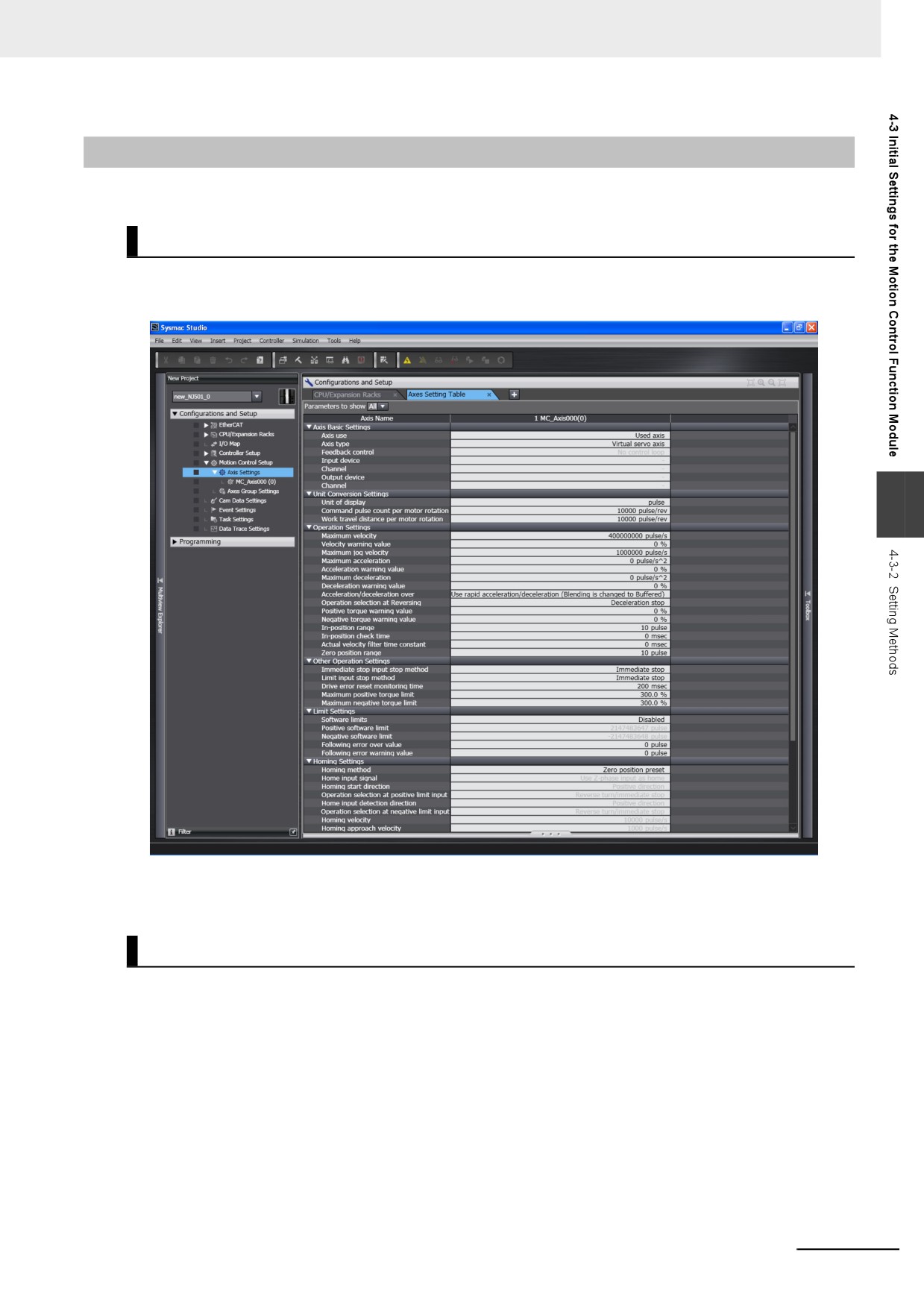
You can use either of the following methods to set motion control parameters.
Method 1: Setting the Motion Control Setup in the Sysmac Studio
Right-click Axis Settings from under Configurations and Setup - Motion Control Setup in the Sys-
mac Studio and make the settings in the Axis Setting Table.
4
Download the motion control parameters to the Controller to save them in the non-volatile memory in
the Controller. The downloaded settings are enabled when the power is turned ON or a download is
performed.
Method 2: Setting with the MC_Write Instruction
You can temporarily overwrite some motion control parameters with the MC_Write instruction.
Refer to the NY-series Industrial Panel PC / Industrial Box PC Motion Control User's Manual (Cat. No.
W559) for details.
4-13
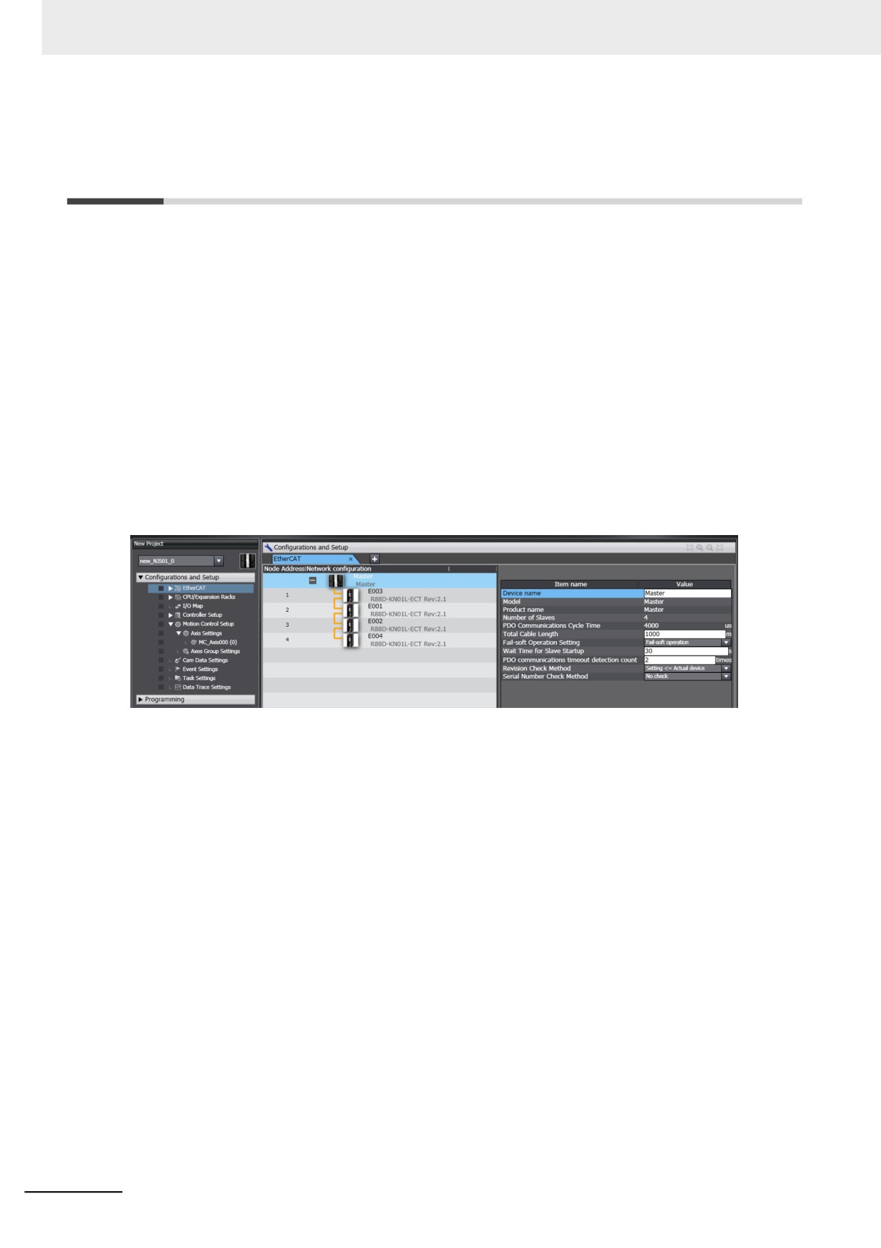
4 Controller Setup
4-4
Initial Settings for the EtherCAT
Master Function Module
This section describes the initial settings that are required for the EtherCAT Master Function Module.
The initial settings for the EtherCAT Master Function Module are listed below.
• Device names
• Total Cable Length
• Fail-soft Operation Settings
• Wait Time for Slave Startup
• PDO Communications Timeout Detection Count
• Revision Check Method
• Serial Number Check Method
Double-click EtherCAT under Configurations and Setup and then select the master on the Sysmac
Studio. The Initial Setting Tab Page for the EtherCAT Master Function Module is displayed.
Refer to the NY-series Industrial Panel PC / Industrial Box PC Built-in EtherCAT Port User's Manual
(Cat. No. W562) for details.
4-14
4 Controller Setup
4-5
Initial Settings for the EtherNet/IP
Function Module
This section describes the initial settings that are required for the EtherNet/IP Function Module.
The initial settings for the EtherNet/IP Function Module are listed below.
• TCP/IP Settings
• Link Settings
• FTP Settings
• SNMP Settings
• SNMP Trap Settings
Select Configurations and Setup − Controller Setup − Built-in EtherNet/IP Port Settings on the
Sysmac Studio to make these settings.
4
Refer to the NY-series Industrial Panel PC / Industrial Box PC Built-in EtherNet/IP Port User's Manual
(Cat. No. W563) for details.
4-15
Designing Tasks
This section describes the task system and types of tasks.
5-1
Overview of Task Designing Procedure
5-2
5-2
Overview of Tasks
5-4
5
5-2-1
Tasks
5-4
5-2-2
Instructions Related to Tasks
5-6
5-2-3
System-defined Variables Related to Tasks
5-6
5-3
Specifications and Basic Operation of Tasks for NY-series Controllers . 5-8
5-3-1
Specifications of Tasks for NY-series Controllers
5-8
5-3-2
Guidelines for Separating Tasks for NY-series Controllers
5-9
5-3-3
Basic Operation of Tasks for NY-series Controllers
5-10
5-3-4
Event Task Execution Conditions for NY-series Controllers
5-16
5-3-5
Event Task Execution Timing for NY-series Controllers
5-21
5-3-6
Operation When Execution Condition Is Met Again Before Execution of the Event
Task Is Completed
5-26
5-4
Tag Data Link Service and System Services
5-27
5-4-1
Execution Priorities and Execution Orders of the Tag Data Link Service and
System Services
5-28
5-4-2
Processing Performed in and Execution Timing of the Tag Data Link Service 5-30
5-4-3
Processing Performed in and Execution Timing of the System Services . . . 5-32
5-5
Assignment and Settings Related to Tasks
5-33
5-5-1
Assigning I/O Refreshing to Tasks
5-33
5-5-2
Assigning Tasks to Programs
5-39
5-5-3
Parameters for Primary Periodic Task and Periodic Tasks
5-40
5-6
Ensuring Concurrency of Variable Values
5-42
5-6-1
Ensuring Concurrency of Variable Values between Tasks
5-42
5-6-2
Variable Access from Outside the Controller
5-49
5-7
Errors Related to Tasks
5-53
5-8
Monitoring Task Execution Status and Task Execution Times
5-55
5-9
Task Design Methods and I/O Response Times
5-59
5-9-1
Checking the Task Execution Time
5-59
5-9-2
Examples of Task Design
5-60
5-9-3
System Input and Output Response Times
5-61
5-1