Omron IPC Machine Controller Industrial Panel PC / Industrial Box PC. Software User’s Manual (Industrial PC Platform NY-series) - page 2
Precautions for Correct Use
Cleaning and Maintenance
• Do not use corrosive substances to clean the product.
• Turn OFF the product or disable the touchscreen for cleaning with water.
31
Regulations and Standards
Regulations and Standards
Conformance to EU Directives
Applicable Directives
• EMC Directives
Concepts
z EMC Directive
OMRON devices that comply with EU Directives also conform to the related EMC standards so that
they can be more easily built into other devices or the overall machine. The actual products have
been checked for conformity to EMC standards.*
Whether the products conform to the standards in the system used by the customer, however, must
be checked by the customer. EMC-related performance of the OMRON devices that comply with EU
Directives will vary depending on the configuration, wiring, and other conditions of the equipment or
control panel on which the OMRON devices are installed. The customer must, therefore, perform
the final check to confirm that devices and the overall machine conform to EMC standards.
* Applicable EMC (Electromagnetic Compatibility) standards are as follows:
EMS (Electromagnetic Susceptibility): EN 61131-2
EMI (Electromagnetic Interference): EN 61131-2 (Radiated emission: 10-m regulations)
z Conformance to EU Directives
The NY-series Controllers comply with EU Directives. To ensure that the machine or device in which
the NY-series Controller is used complies with EU Directives, the Controller must be installed as fol-
lows:
• The NY-series Controller must be installed within a control panel.
• You must use the power supply in SELV specifications for the DC power supplies connected to
DC Power Supply Units and I/O Units.
NY-series Controllers that comply with EU Directives also conform to the Common Emission Standard
(EN 61000-6-4). Radiated emission characteristics (10-m regulations) may vary depending on the con-
figuration of the control panel used, other devices connected to the control panel, wiring, and other con-
ditions.
You must therefore confirm that the overall machine or equipment complies with EC Directives.
Software Licenses and Copyrights
This product incorporates certain third party software. The license and copyright information associ-
ated with this software is available at http://www.fa.omron.co.jp/nj_info_e/.
32
Versions
Versions
Hardware revisions and unit versions are used to manage the hardware and software in NY-series Con-
trollers and EtherCAT slaves. The hardware revision or unit version is updated each time there is a
change in hardware or software specifications. Even when two Units or EtherCAT slaves have the
same model number, they will have functional or performance differences if they have different hard-
ware revisions or unit versions.
Checking Versions
You can check versions on the ID information indications or with the Sysmac Studio.
Checking Unit Versions on ID Information Indications
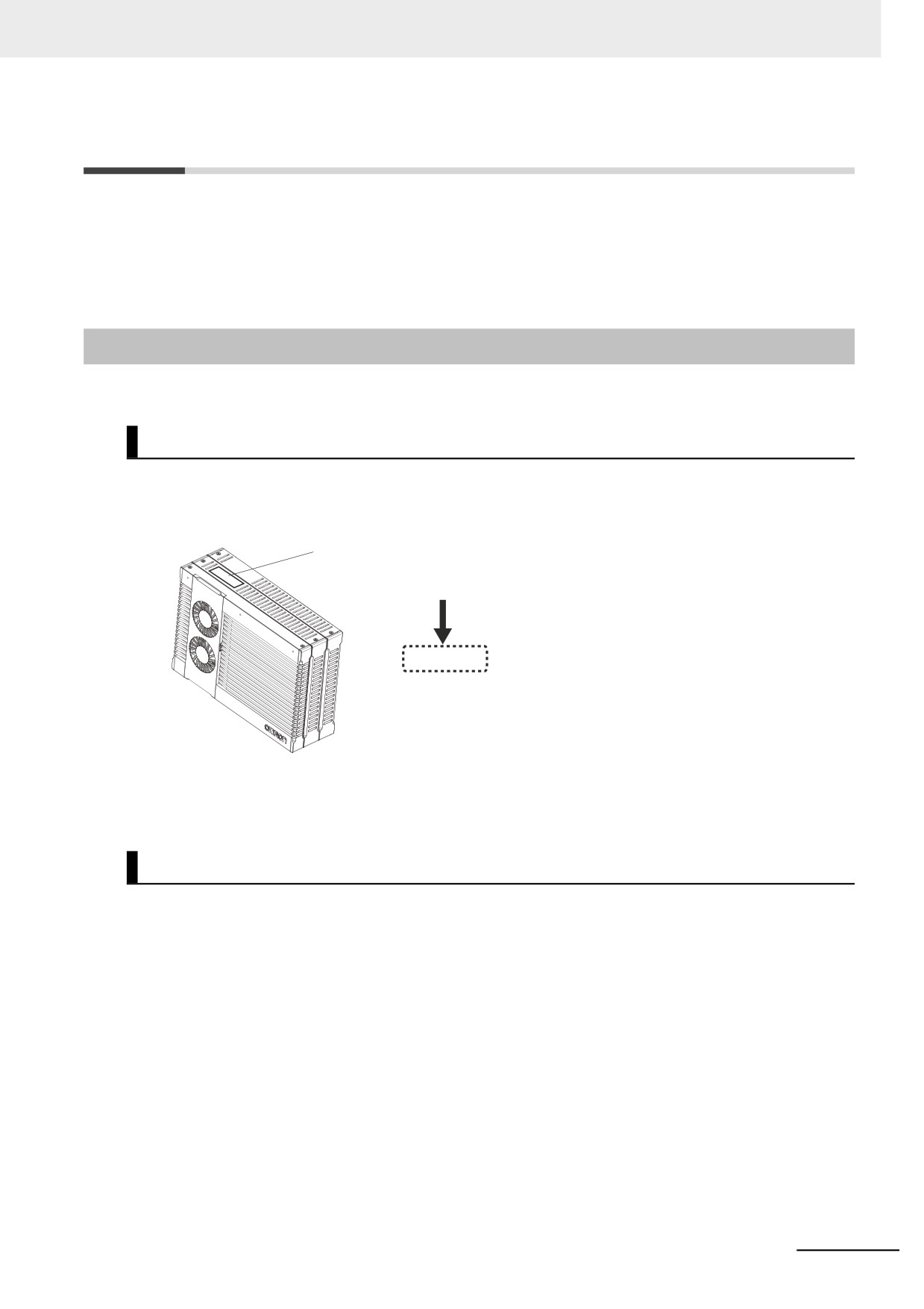
The unit version is given on the ID information indication on the back side of the product.
The ID information on an NY-series NY52- Controller is shown below.
ID information indication
Unit version
Ver.1.
Checking Unit Versions with the Sysmac Studio
You can use the Sysmac Studio to check unit versions. The procedure is different for Units and for Eth-
erCAT slaves.
z Checking the Unit Version of an NY-series Controller
You can use the Production Information while the Sysmac Studio is online to check the unit version
of a Unit. You can only do this for the Controller.
1 Right-click CPU Rack under Configurations and Setup - CPU/Expansion Racks in the Multiv-
iew Explorer and select Production Information.
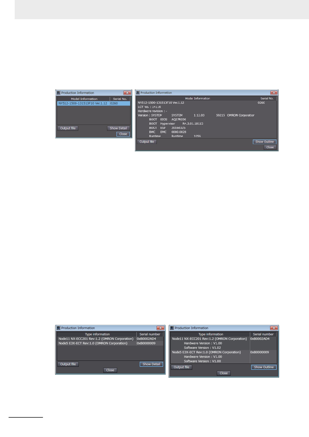
The Production Information Dialog Box is displayed.
33
Versions
z Changing Information Displayed in Production Information Dialog Box
1 Click the Show Detail or Show Outline Button at the lower right of the Production Information
Dialog Box.
The view will change between the production information details and outline.
Outline View
Detail View
The information that is displayed is different for the Outline View and Detail View. The Detail
View displays the unit version, hardware revision, and other versions. The Outline View displays
only the unit version.
z Checking the Unit Version of an EtherCAT Slave
You can use the Production Information while the Sysmac Studio is online to check the unit version
of an EtherCAT slave. Use the following procedure to check the unit version.
1 Double-click EtherCAT under Configurations and Setup in the Multiview Explorer. Or, right-
click EtherCAT under Configurations and Setup and select Edit from the menu.
The EtherCAT Tab Page is displayed.
2 Right-click the master on the EtherCAT Tab Page and select Display Production Information.
The Production Information Dialog Box is displayed.
The unit version is displayed after “Rev.”
z Changing Information Displayed in Production Information Dialog Box
1 Click the Show Detail or Show Outline Button at the lower right of the Production Information
Dialog Box.
The view will change between the production information details and outline.
Outline View
Detail View
34
Related Manuals
Related Manuals
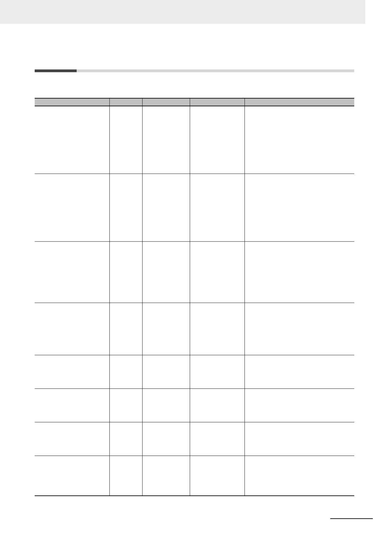
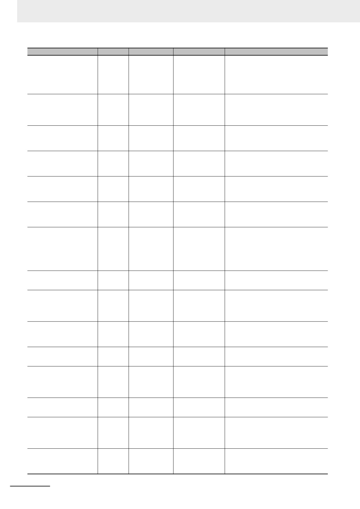
The followings are the manuals related to this manual. Use these manuals for reference.
Manual name
Cat. No.
Model numbers
Application
Description
NY-series
W557
NY532-
Learning the basic
An introduction to the entire NY-series system
IPC Machine Controller
specifications of the
is provided along with the following informa-
Industrial Panel PC
NY-series Industrial
tion on the Industrial Panel PC.
Hardware User’s Manual
Panel PCs, including
• Features and system configuration
introductory informa-
• Introduction
tion, designing, instal-
• Part names and functions
lation, and
maintenance.
• General specifications
Mainly hardware infor-
• Installation and wiring
mation is provided.
• Maintenance and inspection
NY-series
W556
NY512-
Learning the basic
An introduction to the entire NY-series system
IPC Machine Controller
specifications of the
is provided along with the following informa-
Industrial Panel PC
NY-series Industrial
tion on the Industrial Box PC.
Hardware User’s Manual
Box PCs, including
• Features and system configuration
introductory informa-
• Introduction
tion, designing, instal-
• Part names and functions
lation, and
maintenance.
• General specifications
Mainly hardware infor-
• Installation and wiring
mation is provided.
• Maintenance and inspection
NY-series
W568
NY532-
Learning the initial set-
The following information is provided on an
IPC Machine Controller
tings of the NY-series
introduction to the entire NY-series system.
NY512-
Industrial Panel PC / Industrial
Industrial PCs and
• Two OS systems
Box PC
preparations to use
• Initial settings
Setup User's Manual
Controllers.
• Industrial PC Support Utility
• NYCompolet
• Industrial PC API
• Backup and recovery
NY-series
W558
NY532-
Learning how to pro-
The following information is provided on the
IPC Machine Controller
gram and set up the
NY-series Controller functions.
NY512-
Industrial Panel PC / Industrial
Controller functions of
• Controller operation
Box PC
an NY-series Industrial
• Controller features
Software User’s Manual
PC.
• Controller settings
• Programming based on IEC 61131-3 lan-
guage specifications
NY-series Instructions Refer-
W560
NY532-
Learning detailed
The instructions in the instruction set (IEC
ence Manual
specifications on the
61131-3 specifications) are described.
NY512-
basic instructions of
an NY-series Indus-
trial PC.
NY-series
W559
NY532-
Learning about motion
The settings and operation of the Controller
IPC Machine Controller
control settings and
and programming concepts for motion control
NY512-
Industrial Panel PC / Industrial
programming con-
are described.
Box PC
cepts of an NY-series
Motion Control User's Manual
Industrial PC.
NY-series
W561
NY532-
Learning about the
The motion control instructions are described.
Motion Control Instructions
specifications of the
NY512-
Reference Manual
motion control
instructions of an NY-
series Industrial PC.
NY-series
W562
NY532-
Using the built-in Eth-
Information on the built-in EtherCAT port is
IPC Machine Controller
erCAT port in an NY-
provided.
NY512-
Industrial Panel PC / Industrial
series Industrial PC.
This manual provides an introduction and pro-
Box PC
vides information on the configuration, fea-
Built-in EtherCAT Port
tures, and setup.
User’s Manual
35
Related Manuals
Manual name
Cat. No.
Model numbers
Application
Description
NY-series
W563
NY532-
Using the built-in Eth-
Information on the built-in EtherNet/IP port is
IPC Machine Controller
erNet/IP port in an
provided.
NY512-
Industrial Panel PC / Industrial
NY-series Industrial
Information is provided on the basic setup, tag
Box PC
PC.
data links, and other features.
Built-in EtherNet/IP Port
User’s Manual
NJ/NY-series NC Integrated
O030
NJ501-5300
Performing numeri-
Describes the functionality to perform the
Controller User’s Manual
cal control with
numerical control. Use this manual together
NY532-5400
NJ/NY-series Control-
with the NJ/NY-series G code Instructions
lers.
Reference Manual (Cat. No. O031) when pro-
gramming.
NJ/NY-series
O031
NJ501-5300
Learning about the
The G code/M code instructions are
G code Instructions Reference
specifications of the
described. Use this manual together with the
NY532-5400
Manual
G code/M code
NJ/NY-series NC Integrated Controller User's
instructions.
Manual (Cat. No. O030) when programming.
NY-series
W564
NY532-
Learning about the
Concepts on managing errors that may be
Troubleshooting Manual
errors that may be
detected in an NY-series Controller and infor-
NY512-
detected in an NY-
mation on individual errors are described.
series Industrial PC.
Sysmac Studio Version 1
W504
SYSMAC
Learning about the
Describes the operating procedures of the
Operation Manual
-SE2
operating proce-
Sysmac Studio.
dures and functions
of the Sysmac Studio.
CNC Operator
O032
SYSMAC
Learning an introduc-
An introduction of the CNC Operator, installa-
Operation Manual
tion of the CNC Oper-
tion procedures, basic operations, connection
-RTNC0D
ator and how to use
operations, and operating procedures for
it.
main functions are described.
NX-series
W519
NX-ECC
Learning how to use
The following items are described: the overall
EtherCAT Coupler Unit
an NX-series Ether-
system and configuration methods of an Eth-
User’s Manual
CAT Coupler Unit and
erCAT Slave Terminal (which consists of an
EtherCAT Slave Ter-
NX-series EtherCAT Coupler Unit and NX
minals.
Units), and information on hardware, setup,
and functions to set up, control, and monitor
NX Units through EtherCAT.
NX-series
Z930
NX-SL
Learning how to use
Describes the hardware, setup methods, and
Safety Control Unit
NX-SI
NX-series Safety
functions of the NX-series Safety Control
User’s Manual
NX-SO
Control Units
Units.
Vision System
Z340
FH-1
Learning how to use
Describes the software functions, setup and
FH/FZ5 Series Vision System
FH-3
the FH/FZ5-series
operating methods required for using the
User’s Manual
FZ5-L35
Vision Systems.
FH/FZ5-series system.
FZ5-6
FZ5-11
Vision Sensor FQ-M series
Z314
FQ-MS12
Learning how to use
Describes the hardware, setup methods and
Specialized Vision Sensor for
the Specialized
functions of the Specialized Vision Sensors
Positioning
Vision Sensors for
for Positioning.
User’s Manual
Positioning.
Vision Sensor FZ3 Series
Z290
FZ3-
Learning how to use
Describes the software functions, setup and
User’s Manual
the FZ3-series Vision
operating methods of the FZ3-series Vision
Sensors.
Sensors.
Displacement Sensor ZW
Z332
ZW-CE1
Learning how to use
Describes the hardware, setup methods and
series
the ZW-series Dis-
functions of the ZW-series Displacement Sen-
Confocal Fiber Type Displace-
placement Sensors.
sors.
ment Sensor
User’s Manual
NA-series Programmable Ter-
V118
NA5-W
Learning about NA-
Describes the pages and object functions of
minal
series PT pages and
the NA-series Programmable Terminals.
Software User’s Manual
object functions.
NS-series Programmable Ter-
V073
NS15-
Learning how to use
Describes the setup methods, functions, etc. of
minals
NS12-
the NS-series Pro-
the NS-series Programmable Terminals.
Programming Manual
NS10-
grammable Termi-
NS8-
nals.
NS5-
CX-Designer
V099
---
Learning to create
Describes operating procedures for the CX-
User’s Manual
screen data for NS-
Designer.
series Programma-
ble Terminals.
36
Terminology
Terminology
The following table provides terminologies related to the Controller functions.
Term
Description
absolute encoder home offset
This data is used to restore in the Controller the actual position of a Servo Drive
with an absolute encoder. The offset is the difference between the command posi-
tion after homing and the absolute data that is read from the absolute encoder.
array specification
One of the variable specifications. An array variable contains multiple elements of
the same data type. The elements in the array are specified by serial numbers
called subscripts that start from the beginning of the array.
AT
One of the attributes of a variable.
This attribute allows the user to specify what is assigned to a variable. An I/O port
can be specified.
axes group
A functional unit that groups together axes within the Motion Control Function Mod-
ule.
Axes Group Variable
A system-defined variable that is defined as a structure and provides status infor-
mation and some of the axes parameters for an individual axes group.
An Axes Group Variable is used to specify an axes group for motion control instruc-
tions and to monitor the command interpolation velocity, error information, and
other information for the axes group.
axis
A functional unit within the Motion Control Function Module. An axis is assigned to
the drive mechanism in an external Servo Drive or the sensing mechanism in an
external Encoder Input Slave Unit.
Axis Variable
A system-defined variable that is defined as a structure and provides status infor-
mation and some of the axis parameters for an individual axis.
An Axis Variable is used to specify an axis for motion control instructions and to
monitor the command position, error information, and other information for the axis.
basic data type
Any of the data types that are defined by IEC 61131-3.
They include Boolean, bit string, integer, real, duration, date, time of day, date and
time, and text string data types.
"Basic data type" is used as opposed to derivative data types, which are defined by
the user.
cam data variable
A variable that represents the cam data as a structure array.
A cam data variable is an array structure that consists of phases and displace-
ments.
Communications Coupler Unit
The generic name of an interface unit for remote I/O communications on a network
between NX Units and a host network master. For example, an EtherCAT Coupler
Unit is a Communications Coupler Unit for an EtherCAT network.
Constant
One of the attributes of a variable.
If you specify the Constant attribute for a variable, the value of the variable cannot
be written by any instructions, ST operators, or CIP message communications.
Controller
The range of devices that are directly controlled by the Controller functions embedded
in the Real-Time OS in the Industrial Panel PC or Industrial Box PC.
In the NY-series System, it is also called "Controller" that includes the EtherCAT slaves
(including general-purpose slaves and Servo Drives).
Controller error
Errors that are defined by the NY-series System.
“Controller error” is a collective term for major fault level, partial fault level, minor
fault level, and observation Controller events.
Controller event
One of the events in the NY-series System. Controller events are errors and infor-
mation that are defined by the system for user notification. A Controller event
occurs when the system detects a factor that is defined as a Controller event.
Controller function
The functions to perform machine control that are embedded in the Real-Time OS in
the Industrial Panel PC or Industrial Box PC.
Controller information
Information that is defined by the NY-series System that is not an error. It rep-
resents an information Controller event.
derivative data type
A data type that is defined by the user. Structures, unions, and enumerations are
derivative data types.
38
Terminology
Term
Description
device variable
A variable that is used to access a specific device through an I/O port.
download
To transfer data from the Sysmac Studio to the Controller with the synchronization
operation of the Sysmac Studio.
edge
One of the attributes of a variable.
This attribute makes a BOOL variable pass TRUE to a function block when the vari-
able changes from FALSE to TRUE or when it changes from TRUE to FALSE.
enumeration
One of the derivative data types. This data type takes one item from a prepared
name list of enumerators as its value.
enumerator
One of the values that an enumeration can take expressed as a character string.
The value of an enumeration is one of the enumerators.
EtherCAT Master Function Module
One of the function modules. This function module controls the EtherCAT slaves as
the EtherCAT master.
EtherNet/IP Function Module
One of the function modules. This function module controls the built-in EtherNet/IP
port.
event log
A function that recognizes and records errors and other events.
Event Setup
Settings that define user-defined errors and user-defined information.
event task
A task that executes a user program only once when the task execution conditions
are met.
FB
An acronym for "function block."
forced refreshing
Forcing the refreshing of an input from an external device or an output to an exter-
nal device, e.g., when the user debugs a program.
Addresses that are subject to forced refreshing can still be overwritten from the
user program.
FUN
An abbreviation for "function."
function
A POU that is used to create an object that determines a unique output for the
same input, such as for data processing.
function block
A POU that is used to create an object that can have a different output for the same
input, such as for a timer or counter.
function module
One of the functional units of the software configuration of the Controller.
general-purpose slave
Any of the EtherCAT slaves that cannot be assigned to an axis.
global variable
A variable that can be read or written from all POUs (programs, functions, and func-
tion blocks).
I/O map settings
Settings that assign variables to I/O ports. Assignment information between I/O
ports and variables.
I/O port
A logical interface that is used by the Controller to exchange data with an external
device (slave or Unit).
I/O refreshing
Cyclic data exchange with external devices that is performed with predetermined
memory addresses.
information
One of the event levels for Controller events or user-defined events. These are not
errors, but appear in the event log to notify the user of specific information.
Initial Value
One of the attributes of a variable. The variable is set to the initial value in the fol-
lowing situations.
• When power is turned ON
• When the Controller changes to RUN mode
• When you specify to initialize the values when the user program is transferred
• When a major fault level Controller error occurs
inline ST
ST programming that is included within a ladder diagram program.
instruction
The smallest unit of the processing elements that are provided by OMRON for use
in POU algorithms. There are ladder diagram instructions (program inputs and out-
puts), function instructions, function block instructions, and ST statements.
literal
A constant expression that is used in a user program.
local variable
A variable that can be accessed only from inside the POU in which it is defined.
“Local variable” is used as opposed to “global variable.”
Local variables include internal variables, input variables, output variables, in-out
variables, and external variables.
main memory
The memory inside the Controller that is used by the Controller to execute the OS
and user program.
39
Terminology
Term
Description
major fault level Controller error
An error for which all NY-series Controller control operations stop. The Controller
immediately stops user program execution and turns OFF the loads for all slaves
and Units (including remote I/O).
MC Test Run
A function to check motor operation and wiring from the Sysmac Studio.
minor fault level Controller error
An error for which part of the control operations for one of the function modules in
the NY-series Controller stop.
An NY-series Controller continues operation even after a minor fault level Controller
error occurs.
Motion Control Function Module
One of the function modules. The MC Function Module performs motion control
based on commands from the motion control instructions that are executed in the
user program.
motion control instruction
A function block instruction that executes motion control.
The Motion Control Function Module supports instructions that are based on func-
tion blocks for PLCopen® motion control as well as instructions developed specifi-
cally for the Motion Control Function Module.
namespace
A system that is used to group and nest the names of functions, function block defi-
nitions, and data types.
Network Publish
One of the attributes of a variable.
This attribute allows you to use CIP message communications or tag data links to
read/write variables from another Controller or from a host computer.
NX Units
Any of the NX-series Units that perform I/O processing with connected external
devices. The Communications Coupler Units are not included with the NX Units.
observation
One of the event levels for Controller events or user-defined events.
These are minor errors that do not affect control operations, but appear in the event
log to notify the user of specific information.
partial fault level Controller error
An error for which all of the control operations for one of the function modules in the
NY-series Controller stop.
An NY-series Controller continues operation even after a partial fault level Control-
ler error.
PDO communications
An abbreviation for process data communications. Data is exchanged between the
master and slaves on a process data communications cycle. (The process data
communications cycle is the same as the task period of the primary periodic task.)
periodic task
A task for which user program execution and I/O refreshing are performed each
period.
PLC Function Module
One of the function modules. This function module executes the user program and
sends commands to the Motion Control Function Module.
POU
An acronym for "program organization unit." A POU is a unit in a program execution
model that is defined in IEC 61131-3.
A POU contains an algorithm and a local variable table and forms the basic unit
used to build a user program.
There are three types of POUs: programs, functions, and function blocks.
primary periodic task
The task with the highest priority.
process data communications
One type of EtherCAT communications in which process data objects (PDOs) are
used to exchange information cyclically and in realtime. Process data communica-
tions are also called PDO communications.
program
Along with functions and function blocks, one of the three types of POUs.
Programs are assigned to tasks to execute them.
Range Specification
One of the variable specifications. You can specify a range for a variable in
advance. The variable can take only values that are in the specified range.
Retain
One of the attributes of a variable. The values of variables with a Retain attribute
are held at the following times. (Variables without a Retain attribute are set to their
initial values.)
• When power is turned ON after a power interruption
• When the Controller changes to RUN mode
• When you specify to not initialize the values when the user program is transferred
SDO communications
One type of EtherCAT communications in which service data objects (SDOs) are
used to transmit information whenever required.
40
Terminology
Term
Description
Servo Drive/encoder input slave
Any of the EtherCAT slaves that is assigned to an axis. In the NY-series System, it
would be a Servo Drive or Encoder Input Slave Unit.
slave
A device that performs remote I/O for a master.
slave and Unit configurations
A generic term for the EtherCAT configuration and Unit configuration.
Slave Terminal
A building-block remote I/O terminal to which a Communications Coupler Unit and
NX Units are mounted. A Slave Terminal is one type of slave.
Special Unit Setup
A generic term for the settings for a Special Unit, including the settings in allocated
DM Area words.
structure
One of the derivative data types. It consists of multiple data types placed together
into a layered structure.
synchronization
A function that automatically compares the information in the NY-series Controller
with the information in the Sysmac Studio, displays any differences and locations in
a hierarchical form, and can be used to synchronize the information.
Sysmac Studio
A computer software application for setting, programming, debugging, and trouble-
shooting NY-series Controllers. It also provides operations for motion control and a
Simulator.
system common processing
System processing that is performed by the Controller to perform I/O refreshing and
the user program execution within a task. Exclusive control of variables between
tasks, data trace processing, and other processing is performed.
system service
Non-task related processing that is performed by the Controller. The system service
includes communications processing, Virtual SD Memory Card access processing,
self-diagnosis processing, and other processing.
system-defined variable
A variable for which all attributes are defined by the system and cannot be changed
by the user.
task
An attribute that defines when a program is executed.
task period
The interval at which the primary periodic task or a periodic task is executed.
union
One of the derivative data types. It allows you to handle the same data as different
data types.
Unit
A device that mounts to the Communications Coupler Unit.
Unit configuration
The configuration information for the Units that are set on the Sysmac Studio. This
information tells what Unit models are connected to the Controller and where they
are connected.
upload
To transfer data from the Controller to the Sysmac Studio with the synchronization
operation of the Sysmac Studio.
user program
All of the programs in one project.
user-defined event
One of the events in the NY-series System. These events are defined by the user.
“User-defined events” is a generic term for user-defined errors and user-defined
information.
user-defined variable
A variable for which all of the attributes are defined by the user and can be changed
by the user.
variable
A representation of data, such as a numeric value or character string, that is used in
a user program.
You can change the value of a variable by assigned the required value. “Variable” is
used as opposed to “constant,” for which the value does not change.
variable memory
A memory area that contains the present values of variables that do not have AT
specifications. It can be accessed only with variables without an AT attribute.
Virtual SD Memory Card
A shared folder for the Controller functions to handle files.
An SD Memory Card is used in the NJ/NX-series CPU Unit which is treated as the
Controller for Sysmac. In the NY-series Controller, however, a shared folder with
Windows is handled as a Virtual SD Memory Card.
Therefore, the SD Memory Card is sometimes given without "virtual".
41
Revision History
Revision History
A manual revision code appears as a suffix to the catalog number on the front and back covers of the
manual.
Cat. No.
W558-E1-05
Revision code
Revision code
Date
Revised content
01
September 2016
Original production
02
April 2017
• Added information on the functions supported by unit ver-
sion 1.14 of the Controllers.
• Corrected mistakes.
03
October 2017
• Added information on the functions supported by unit ver-
sion 1.16 of the Controllers.
• Corrected mistakes.
04
April 2018
• Added information on the functions supported by unit ver-
sion 1.18 of the Controllers.
05
July 2019
• Added information on the functions supported by unit ver-
sion 1.21 of the Controllers.
• Corrected mistakes.
42
1
Introduction to NY-series Controllers
This section describes the features, basic system configuration, specifications, and
overall operating procedure of an NY-series Controller.
1-1
The NY-series Controllers
1-2
1-1-1
Features
1-3
1-1-2
Introduction to the System Configurations
1-5
1-2
Main Specifications
1-7
1-3
Product Model Numbers
1-9
1-4
Overall Operating Procedure for the NY-series Controller
1-10
1-4-1
Overall Procedure
1-10
1-4-2
Procedure Details
1-11
1-1
1 Introduction to NY-series Controllers
1-1
The NY-series Controllers
The Industrial PC Platform NY-series Controllers are next-generation machine automation controllers
that provide the functionality and high-speed performance that are required for machine control.
They provide the safety, reliability, and maintainability that are required of industrial controllers.
The Industrial PC Platform NY-series Controllers provide the functionality of previous OMRON PLCs,
and they also provide the functionality that is required for motion control. Synchronized control of I/O
devices on high-speed EtherCAT can be applied to safety devices, vision systems, motion equipment,
discrete I/O, and more.
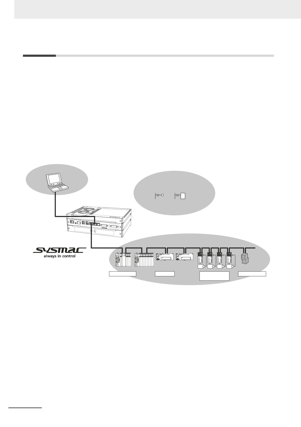
OMRON offers the new Sysmac Series of control devices designed with unified communications speci-
fications and user interface specifications. The Industrial PC Platform NY-series Controllers are part of
the Sysmac Series. You can use them together with EtherCAT slaves, other Sysmac products, and the
Sysmac Studio Automation Software to achieve optimum functionality and ease of operation. With a
system that is created from Sysmac products, you can connect components and operate the system
through unified concepts and usability.
Sysmac Studio
Automation Software
Multitasking, Synchronized Control
Sequence control Motion control
NY-series Controller
IEC programming
EtherCAT control network
Safety devices
I/O controls
Servo Drives and
Machine vision
Inverters
1-2
1 Introduction to NY-series Controllers
1-1-1
Features
This section describes features of the Controller functions in the NY-series IPC Machine Controller
Industrial Panel PC / Industrial Box PC.
Hardware Features
1
z
Standard-feature EtherCAT Control Network Support
The NY-series Controllers provide an EtherCAT master port for EtherCAT communications. Ether-
CAT is an advanced industrial network system that achieves faster, more-efficient communications.
It is based on Ethernet. Each node achieves a short fixed communications cycle time by transmitting
Ethernet frames at high speed. The standard-feature EtherCAT control network allows you to con-
nect all of the devices required for machine control (e.g., I/O systems, Servo Drives, Inverters, and
machine vision) to the same network.
z
Support for EtherCAT Slave Terminals
You can use EtherCAT Slave Terminals to save space. You can also flexibly build systems with the
wide variety of NX Units.
z
Achieving a Safety Subsystem on EtherCAT
You can use NX-series Safety Control Units to integrate safety controls in a sequence and motion
control system as a subsystem on EtherCAT.
z
Standard-feature EtherNet/IP Communications Port
The NY-series Controllers provide an EtherNet/IP port for EtherNet/IP communications. EtherNet/IP
is a multi-vendor industrial network that uses Ethernet. You can use it for networks between Control-
lers or as a field network. The use of standard Ethernet technology allows you to connect to many
different types of general-purpose Ethernet devices.
z
Highly Reliable Hardware
The NY-series Controllers provide the hardware reliability and RAS functions that you expect of a
PLC.
z
Parallel Execution of Tasks with a Multi-core Processor
With a multi-core processor, the NY532- and NY512-1 can execute the task, the tag
data link service, and system services in parallel. This enables high-speed control of even large-
scale devices.
1-3
1 Introduction to NY-series Controllers
Software Features
z
Integrated Sequence Control and Motion Control
An NY-series Controller can perform both sequence control and motion control. You can simultane-
ously achieve both sequence control and multi-axes synchronized control. Sequence control,
motion control, and I/O refreshing are all executed in the same control period. The same control
period is also used for the process data communications cycle for EtherCAT. This enables precise
sequence and motion control in a fixed period with very little deviation.
z
Multitasking
You assign I/O refreshing and programs to tasks and then specify execution conditions and execu-
tion order for them to flexibly combine controls that suit the application.
z
Programming Languages Based on the IEC 61131-3 International Standard
The NY-series Controllers support language specifications that are based on IEC 61131-3. To these,
OMRON has added our own improvements. Motion control instructions that are based on PLCo-
pen® standards and an instruction set (POUs) that follows IEC rules are provided.
z
Programming with Variables to Eliminate Worrying about the Memory Map
You access all data through variables in the same way as for the advanced programming languages
that are used on computers. Memory in the Controller is automatically assigned to the variables that
you create so that you do not have to remember the physical addresses.
z
A Wealth of Security Features
The many security features of the NY-series Controllers include operation authority settings and
restriction of program execution with IDs.
z
Complete Controller Monitoring
The Controller monitors events in all parts of the Controller, including mounted EtherCAT slaves.
Troubleshooting information for errors is displayed on the Sysmac Studio or on an NS/NA-series PT.
Events are also recorded in logs.
z
Sysmac Studio Automation Software
The Sysmac Studio provides an integrated development environment that covers not only the Con-
troller, but also covers peripheral devices and devices on EtherCAT. You can use consistent proce-
dures for all devices regardless of the differences in the devices. The Sysmac Studio supports all
phases of Controller application, from designing through debugging, simulations, commissioning,
and changes during operation.
z
A Wealth of Simulation Features
The many simulation features include execution and debugging on a virtual controller.
1-4
1 Introduction to NY-series Controllers
1-1-2
Introduction to the System Configurations
The NY Series supports the following system configurations.
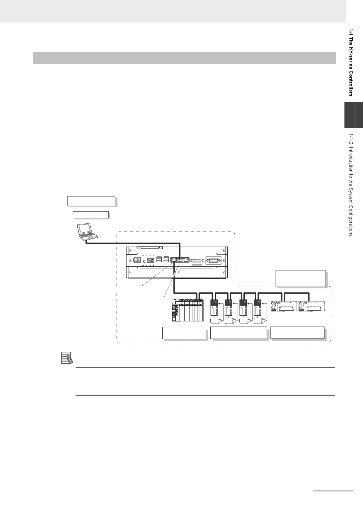
z Basic System Configurations
The NY-series basic configurations include the EtherCAT network configuration and the Support
Software.
• EtherCAT Network Configuration
1
You can use the built-in EtherCAT port to connect to EtherCAT Slave Terminals, to general-pur-
pose slaves for analog and digital I/O, and to Servo Drives and encoder input slaves. An Ether-
CAT network configuration enables precise sequence and motion control in a fixed cycle with
very little deviation.
• Support Software
The Support Software is connected to the built-in EtherNet/IP port with an Ethernet cable.
Refer to 10-2 Connection with Sysmac Studio for details on the connection configuration of the
Support Software.
Support Software
Sysmac Studio
NY-series Controller
LAN
EtherNet/IP
EtherCAT Network
Configuration
Built-in EtherCAT port
EtherCAT
Built-in EtherNet/IP port
Servo Drive/encoder
Slave Terminal
General-purpose slaves
input slaves
Additional Information
You can connect the Sysmac Studio directly to the Communications Coupler Unit to set up the
Slave Terminal. Refer to the NX-series EtherCAT Coupler Units User’s Manual (Cat. No. W519)
for details.
1-5
1 Introduction to NY-series Controllers
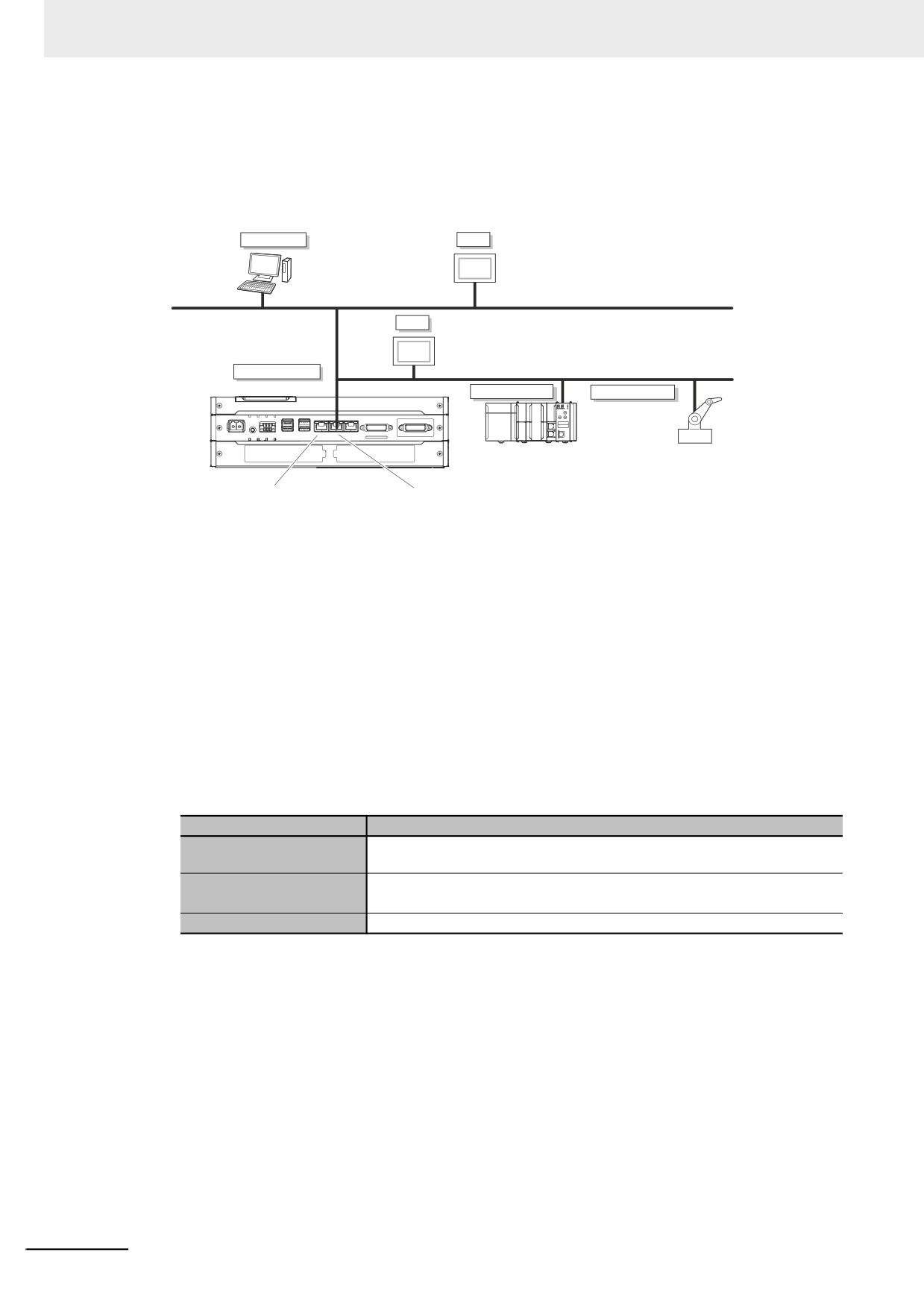
z Network Configurations
• Host computers, HMIs, and other NJ/NX/NY-series Controllers are connected to the built-in Ether-
Net/IP port.
Host computer
HMI
EtherNet/IP
HMI
NY-series Controller
EtherNet/IP
NJ/NX-series
EtherNet/IP slave
Built-in EtherCAT port
Built-in EtherNet/IP port
Refer to Section 10 Communications Setup for details on the network configuration.
z Support Software
You can use the following Support Software to set up, monitor, and debug NY-series Controller func-
tions.
• Sysmac Studio
The Sysmac Studio is the main Support Software that you use for an NY-series Controller. On it,
you can set up the Controller configurations, parameters, and programs, and you can debug
and simulate operation.
• Other Support Software
The following Support Software is also included in the Sysmac Studio Software Package Stan-
dard Edition.
Configuration software
Application
The Sysmac Studio is used for sequence control, motion control, and all
Sysmac Studio
other operations except those described below.
The Network Configurator is used for tag data links on EtherNet/IP ports or
Network Configurator
Units.*1
CX-Designer
The CX-Designer is used to create screens for NS-series PTs.
*1
Use the Network Configurator if a CS/CJ-series PLC operates as the originator device.
Refer to the NY-series Industrial Panel PC / Industrial Box PC Setup User's Manual (Cat. No. W568) for
information on Support Software other than the NY-series Controller functions.
1-6
1 Introduction to NY-series Controllers
1-2
Main Specifications
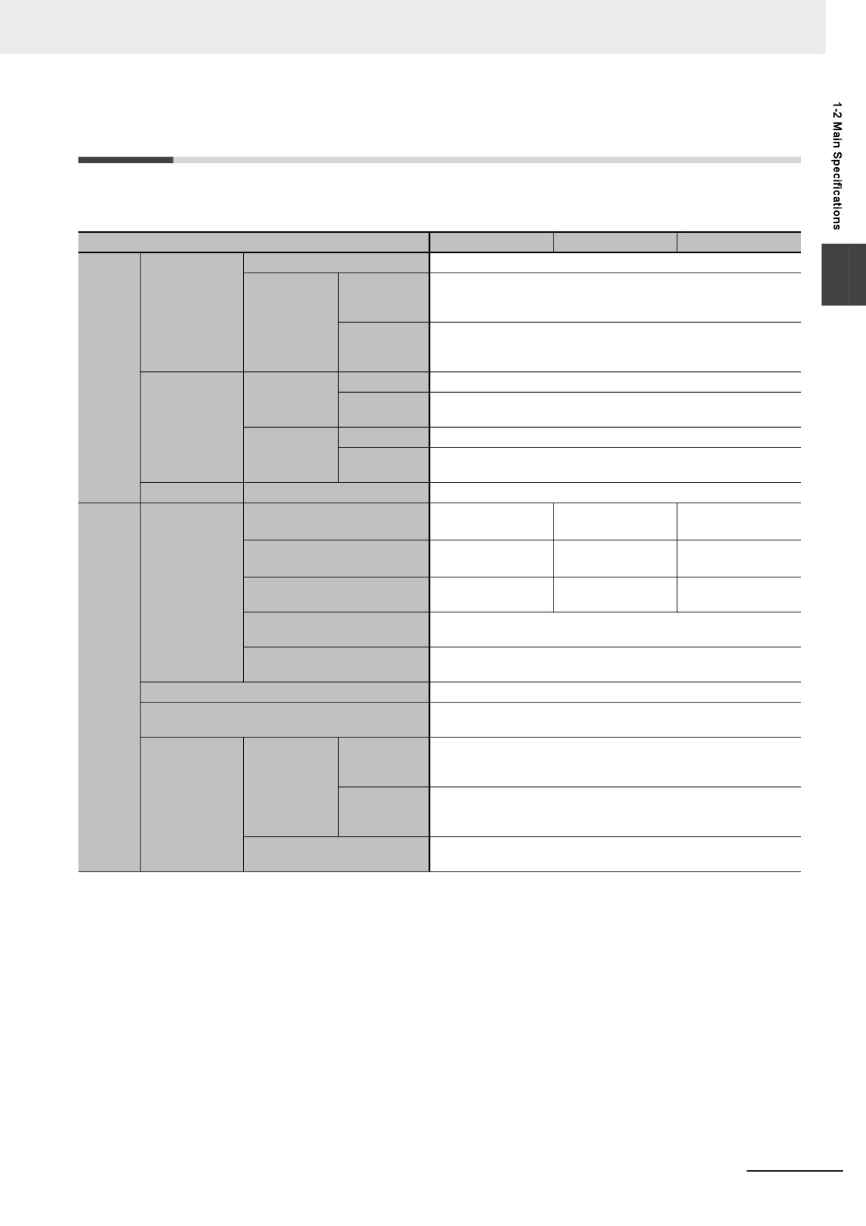
This section gives the main specifications of the NY-series Controller functions. Refer to A-1 Specifica-
tions for general specifications, performance specifications, and function specifications.
Item
NY52-15
NY52-4
NY52-13
Size
40 MB
1
Number of
3,000
POU defini-
Program capac-
tions
ity*1
Quantity
Number of
24,000
POU
instances
Program-
ming
Size
4 MB
Retain attri-
Number of
40,000
butes
Memory capac-
variables
ity for variables
Size
64 MB
No Retain attri-
Number of
180,000
butes
variables
Data types
Number of data types
4,000
Maximum number of controlled
64 axes
32 axes
16 axes
axes*2
Maximum number of used real
64 axes
32 axes
16 axes
axes*3
Number of con-
Maximum number of axes for
64 axes
32 axes
16 axes
trolled axes
single-axis control
Maximum number of axes for
4 axes per axes group
linear interpolation axis control
Number of axes for circular
2 axes per axes group
interpolation axis control
Motion
control
Maximum number of axes groups
32 axes groups
The same control period as that is used for the process data commu-
Motion control period
nications cycle for EtherCAT.
Maximum
65,535 points
points per
Number of
cam table
cam data
Maximum
1,048,560 points
Cams
points
points for all
cam tables
Maximum number of cam
640 tables
tables
1-7
1 Introduction to NY-series Controllers
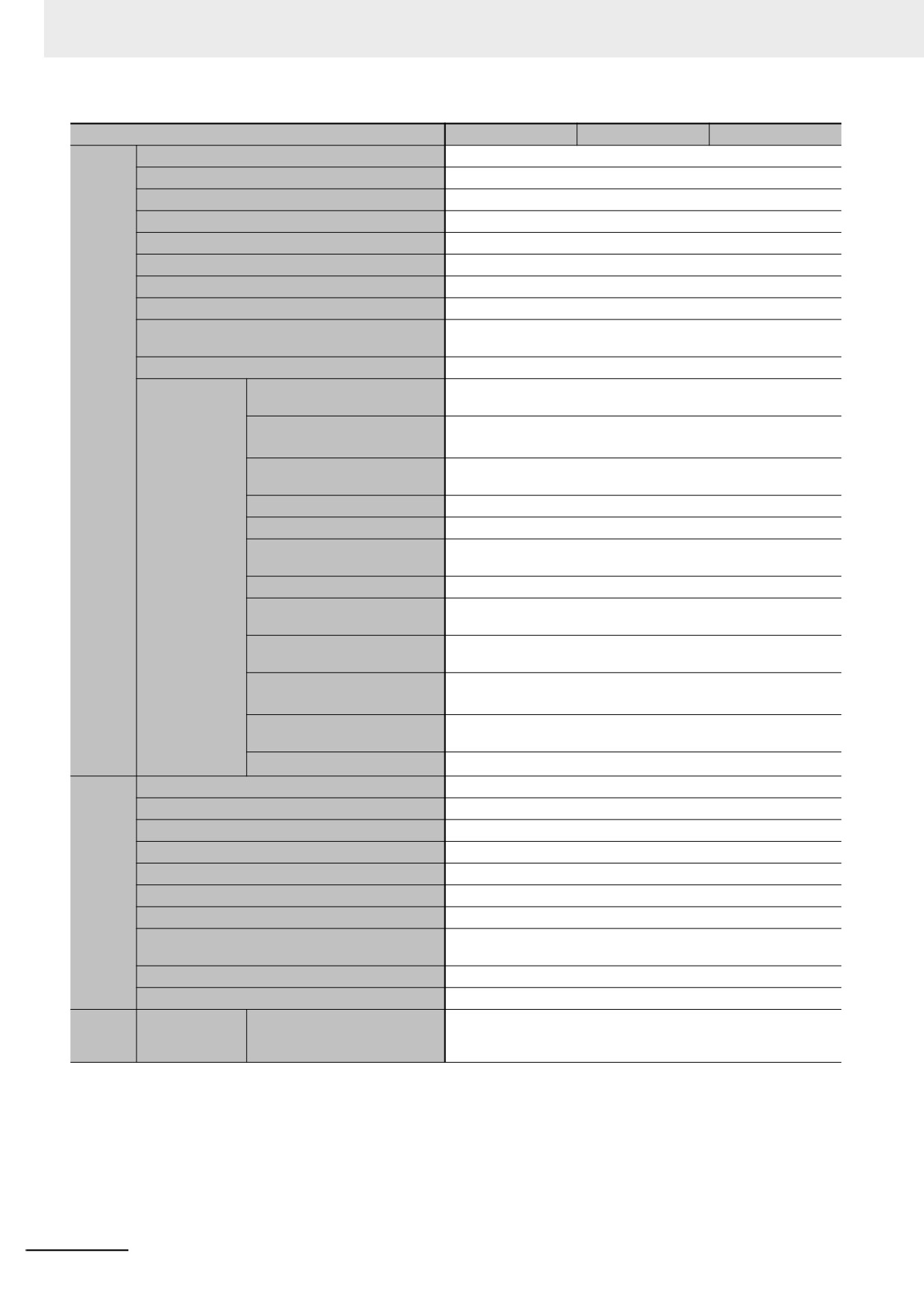
Item
NY52-15
NY52-4
NY52-13
Number of ports
1
Physical layer
10BASE-T, 100BASE-TX, or 1000BASE-T
Frame length
1,514 bytes max.
Media access method
CSMA/CD
Modulation
Baseband
Topology
Star
Baud rate
1 Gbps (1000BASE-T)
Transmission media
STP (shielded, twisted-pair) cable of Ethernet category 5, 5e or higher
Maximum transmission distance between Ether-
100 m
net switch and node
Maximum number of cascade connections
There are no restrictions if an Ethernet switch is used.
Maximum number of connec-
128
tions
Can be set for each connection.
Built-in
Packet interval*4
1 to 10,000 ms in 1-ms increments
Ether-
Net/IP
Permissible communications
20,000 pps*5 (including heartbeat)
port
band
Maximum number of tag sets
128
Tag types
Network variables
Number of tags per connection
8 (7 tags if Controller status is included in the tag set.)
CIP service: Tag
(= 1 tag set)
data links
(cyclic commu-
Maximum number of tags
256
nications)
Maximum link data size per
184,832 bytes
node (total size for all tags)
Maximum data size per connec-
1,444 bytes
tion
Maximum number of registra-
128
ble tag sets
(1 connection = 1 tag set)
1,444 bytes (Two bytes are used if Controller status is included in the
Maximum tag set size
tag set.)
Multi-cast packet filter*6
Supported.
Communications standard
IEC 61158 Type12
EtherCAT master specifications
Class B (Feature Pack Motion Control compliant)
Physical layer
100BASE-TX
Modulation
Baseband
Built-in
Baud rate
100 Mbps (100BASE-TX)
Ether-
Duplex mode
Auto
CAT port
Topology
Line, daisy chain, and branching
Twisted-pair cable of category 5 or higher (double-shielded straight
Transmission media
cable with aluminum tape and braiding)
Maximum transmission distance between nodes
100 m
Maximum number of slaves
128
Unit con-
Maximum num-
4,096
Maximum number of NX Units
figura-
ber of connect-
for entire controller
(On EtherCAT Slave Terminals)
tion
able Units
*1. This is the capacity for the execution objects and variable tables (including variable names).
*2. This is the total for all axis types.
*3. This is the total number of axes that are set as servo axes or encoder axes and are also set as used axes.
*4. Data will be refreshed at the set interval, regardless of the number of nodes.
*5.
“pps” means packets per second, i.e., the number of communications packets that can be sent or received in one second.
*6. As the EtherNet/IP port implements the IGMP client, unnecessary multi-cast packets can be filtered by using an Ethernet switch that sup-
ports IGMP Snooping.
1-8
1 Introduction to NY-series Controllers
1-3
Product Model Numbers
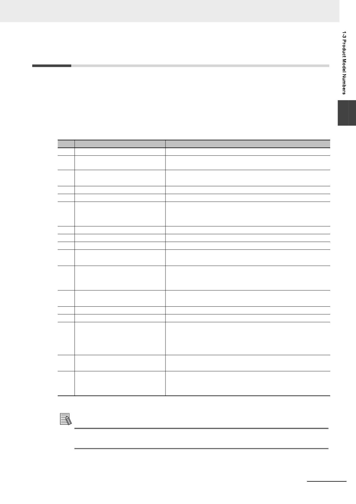
You can identify the number of controlled axes and hardware configurations for the models of the NY-
series Controllers.
NY
532 - 1 5 0 0 - 1 1 2 2 1 3C2 2
1
1
2
3
4
5
6
7
8
9
10 11 12 13 14 15 16 17
No.
Item
Option
1
Series name
NY
:
NY-series Industrial PC Platform
2
Controller specifications
5
:
Large scale, high speed and high precision control applica-
tion for up to 64 axes.
3
Model type
1
:
Industrial Box PC
3
:
Industrial Panel PC
4
Sequential number
2
:
Latest edition
5
Function module
1
:
Standard
6
Number of axes for motion control
3
:
16 axes
4
:
32 axes
5
:
64 axes
7
Additional Function Software Module
0
:
---
8
Reserved.
0
:
---
9
Expansion slots
1
:
1 PCIe slot
10
Frame type
1
:
Aluminum frame, black, and Projected Capacitive Touch type
X
:
No display (Industrial Box PC)
11
Display size
1
:
12.1 inch
2
:
15.4 inch
X
:
No display (Industrial Box PC)
12
OS
1
:
Windows Embedded Standard 7 32bit
2
:
Windows Embedded Standard 7 64bit
13
Processor
1
:
Intel® Core™ i7-4700EQ Processor
14
Main memory
3
:
8 GB, non-ECC
15
Storage
8
:
32 GB, SSD SLC
9
:
64 GB, SSD SLC
C
:
320 GB, HDD
K
:
128GB, SSD iMLC
16
Optional interface
1
:
RS-232C
2
:
DVI-D
17
Logo
0
:
OMRON
2
:
Customization
X
:
No display (Industrial Box PC)
Additional Information
This manual mainly describes the Controller functions, so that the model numbers given after
No.9 may be omitted for which there are no influences to the Controller functions.
1-9
1 Introduction to NY-series Controllers
1-4
Overall Operating Procedure for the
NY-series Controller
This section gives the overall operating procedure of the NY-series Controller functions and then
describes it in more detail.
1-4-1
Overall Procedure
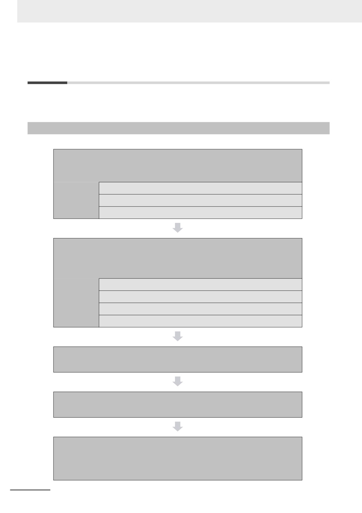
The overall procedure to use the NY-series Controller functions is given below.
Step 1. Software Design
Design the overall system configuration, task configuration, programs, and vari-
ables.
Step 1-1 Designing I/O and Processing
Step 1-2 Designing Tasks
Step 1-3 Designing Programs
Step 2. Software Setups and Programming
Create the system configurations that you designed in step 1 on the Support Soft-
ware and assign the variables. Create the tasks and programs, and debug them,
e.g., with simulations.
Step 2-1 Slave and Unit Configurations
Step 2-2 Controller Setup
Step 2-3 Programming
Step 2-4 Offline Debugging
Step 3. Mounting and Setting Hardware
Mount the Units and make the required hardware settings.
Step 4. Wiring
Connect the network cables and wire the I/O.
Step 5. Checking Operation and Starting Actual Operation
on the Actual System
Connect the Support Software to the physical system and download the project.
Check operation on the physical system and then start actual system operation.
1-10
1 Introduction to NY-series Controllers
1-4-2
Procedure Details
Step 1. Software Design
Step
Description
Reference
• External I/O devices and Unit configuration
Step 1-1
NY-series Industrial Panel
• Refresh periods for external devices
PC Hardware User’s Man-
Designing I/O and
1
• Program contents
ual (Cat No. W557)
Processing
NY-series Industrial Box PC
Hardware User’s Manual
(Cat. No. W556)
• Task configuration
Step 1-2
4-2-3 Task Settings
• Relationship between tasks and programs
Designing Tasks
• Task periods
• Slave and Unit refresh times
• Exclusive control methods for variables between tasks
Step 1-3
Designing Pro-
grams
• Programs
POU (Program
Section 6 Programming
Organization Unit)
• Functions and function blocks
Design
• Determining the algorithm languages
• Defining variables that you can use in more than one POU and
Variable Design
6-3 Variables
variables that you use in only specific POUs
• Defining the variables names for the device variables that you use
to access slaves and Units
• Defining the attributes of variables, such as the Name and Retain
attributes
• Designing the data types of variables
Step 2. Software Setups and Programming
Step
Description
Sysmac Studio Oper-
Reference
ations
1. Create a project in the Sysmac Studio.
Project Creation
New Project Button
Sysmac Studio Version 1
2. Insert a Controller.
Operation Manual (Cat. No.
Insert − Controller
W504)
1-11
1 Introduction to NY-series Controllers
The following Controller Configurations and Setup and the Programming and Task Settings can be performed in either
order.
Step 2-1
Slave and Unit
Configurations
1. Creating the slave configuration and
1) Creating the Slave
EtherCAT Slave Set-
3-2 Creating the EtherCAT
Unit configuration either offline or
and Unit Configura-
ting Editor
Slave Configuration
online. (For online configuration, make
tions
Unit Editor
NX-series EtherCAT Cou-
the online connection that is described
pler Unit User’s Manual
in step 5.)
(Cat. No. W519)
2. Setting up any Slave Terminals that are
used.
2) Assigning Device
Registering device variables in variable
I/O Map
3-3 I/O Ports and Device
Variables to I/O Ports
tables (Variable names are user defined or
Variables
automatically created.)
(The following step is for motion control.)
3) Creating the Axes
Creating the axes and setting them as real
Configurations and
3-5 Creating the Axes and
and Assigning Them
axes or virtual axes. Creating axes groups
Setup − Motion Con-
Assigning Them to the
to the Servo
to perform interpolated axes control.
trol Setup
Servo Drives/Encoder Input
Drive/Encoder Input
Slaves
Slaves
Step 2-2
Setting the following parameters from the
Section 4 Controller Setup
Controller Setup
Sysmac Studio
Setting the initial values for the PLC
Configurations and
4-2 Initial Settings for the
Function Module
Setup − Controller
PLC Function Module
Setup − Operation
Settings
(To use motion control)
Configurations and
4-3 Initial Settings for the
Setting the initial settings for the
Setup − Motion Con-
Motion Control Function
Motion Control Function Module
trol Setup
Module
Setting the initial values for the Ether-
Configurations and
4-4 Initial Settings for the
CAT Function Module
Setup − EtherCAT
EtherCAT Master Function
Module
Setting the initial values for the Ether-
Configurations and
4-5 Initial Settings for the
Net/IP Function Module
Setup − Controller
EtherNet/IP Function Mod-
Setup − Built-in Ether-
ule
Net/IP Port Settings
1-12
1 Introduction to NY-series Controllers
Step 2-3
Programming
• Registering the variables used by more
1) Registering Vari-
Global Variable Table
Sysmac Studio Version 1
than one POU in the global variable
ables
Editor
Operation Manual (Cat. No.
table with Sysmac Studio
W504)
Local Variable Table
• Registering the local variable table for
1
Editor
6-3 Variables
each program
• Registering the local variable table for
each function block and function
2) Writing Algorithms
Writing the algorithms for the POUs (pro-
Programming Editor
Section 6 Programming
for POUs
grams, function blocks, and functions) in
NY-series Instructions Ref-
the required languages
erence Manual (Cat. No.
W560) and NY-series
Motion Control Instructions
Reference Manual (Cat. No.
W561)
3) Setting the Tasks
Making task settings
Configurations and
4-2-3 Task Settings
Setup − Task Settings
Step 2-4
Checking the algorithms on the Simulator
Section 7 Checking Opera-
Offline Debugging
(virtual controller)
tion and Actual Operation
Step 3. Mounting and Setting Hardware
Step
Description
Reference
• Mounting each part
1. Mounting
NY-series Industrial Panel
• Installation in a control panel
PC Hardware User’s Man-
ual (Cat No. W557)
NY-series Industrial Box PC
Hardware User’s Manual
(Cat. No. W556)
• Setting the shared folder used as a Virtual SD Memory Card in
2. Setting the
NY-series Industrial Panel
Windows.
Shared Folder
PC / Industrial Box PC
Setup User’s Manual (Cat
No. W568)
• Setting the node addresses of the EtherCAT slaves
3. Setting Hard-
Operation manuals for the
ware
EtherCAT slaves
1-13
1 Introduction to NY-series Controllers
Step 4. Wiring
Step
Description
Reference
• Connecting the built-in EtherCAT port
1. Connecting
NY-series Industrial Panel
• Connecting the built-in EtherNet/IP port
PC Hardware User’s Man-
Ethernet Cable
ual (Cat No. W557)
NY-series Industrial Box PC
Hardware User’s Manual
(Cat. No. W556)
• Wiring I/O to EtherCAT slaves
2. Wiring I/O
Operation manuals for the
EtherCAT slaves
NY-series Industrial Panel
PC Hardware User’s Man-
ual (Cat No. W557)
NY-series Industrial Box PC
Hardware User’s Manual
(Cat. No. W556)
• Checking wiring
Sysmac Studio Version 1
Operation Manual (Cat. No.
W504)
• Connecting the built-in EtherNet/IP port
3. Connecting the
Sysmac Studio Version 1
Computer That
Operation Manual (Cat. No.
W504)
Runs the Sysmac
Studio
Step 5. Checking Operation and Starting Operation on the Actual System
Step
Description
Sysmac Studio
Reference
Operations
Turn ON the power supply to the Control-
1. Online Connec-
Controller − Commu-
Section 7 Checking Opera-
ler and place the Sysmac Studio online.
tion to Sysmac Stu-
nications Setup
tion and Actual Operation
Then, download the project.*
dio and Project
Controller − Synchro-
(Perform this step before you create the
Download
nization
slave configuration or Unit configuration
from the mounted Units in step 2-1.)
1-14
1 Introduction to NY-series Controllers
1. Check the wiring by using forced
2. Operation Check
Section 7 Checking Opera-
refreshing of real I/O from the I/O Map
on Controller
tion and Actual Operation
or Watch Tab Page.
2. For motion control, use the MC Test
Run operations in PROGRAM mode to
check the wiring. Then check the motor
rotation directions for jogging, travel
distances for relative positioning (e.g.,
for electronic gear settings), and hom-
ing operation.
1
3. Change the Controller to RUN mode
and check the operation of the user
program.
3. Actual Controller
Start actual operation.
Operation
* Use the Synchronize Menu of the Sysmac Studio to download the project.
1-15
2
NY-series Controller Operation
This section provides information that is necessary to use the Controller, including how
the Controller works and the operations that it performs depending on the status of the
Controller.
2-1
Overview of NY-series Controller Operation
2-2
2-1-1
Introduction to NY-series Controller
2-2
2-1-2
Overview of Operation According to NY-series Controller Status
2-3
2-2
Software
2-4
2-2-1
Software Configuration
2-4
2-2-2
Operation of Software
2-5
2-3
Accessing I/O
2-10
2-3-1
Types of Variables
2-10
2-3-2
Accessing I/O with Variables
2-13
2-4
Sequence Control and Motion Control
2-16
2-4-1
Overview of Control
2-16
2-4-2
Sequence Control System
2-18
2-4-3
Motion Control System
2-19
2-4-4
Synchronizing Sequence Control and Motion Control
2-20
2-5
Overview of Controller Data
2-21
2-6
Operation for Controller Status
2-22
2-6-1
Controller Status
2-22
2-6-2
Operation for Controller Status
2-24
2-6-3
Operating Modes
2-25
2-7
Monitoring and Changing Windows Status
2-28
2-7-1
Windows Status
2-28
2-7-2
Monitoring Windows Status
2-28
2-7-3
Changing Windows Status
2-29
2-7-4
Changes in Windows Status
2-29
2-8
Shutdown
2-30
2-8-1
Processing When Power Is Interrupted or Power Supply Button Is Pressed
2-31
2-8-2
Settings of Shutdown
2-32
2-8-3
Contents of Shutdown
2-33
2-9
Resetting the Controller
2-36
2-1
2 NY-series Controller Operation
2-1
Overview of NY-series Controller Operation
This section describes the operation of the Controller and gives an overview of how it operates depend-
ing on the status of the Controller.
2-1-1
Introduction to NY-series Controller
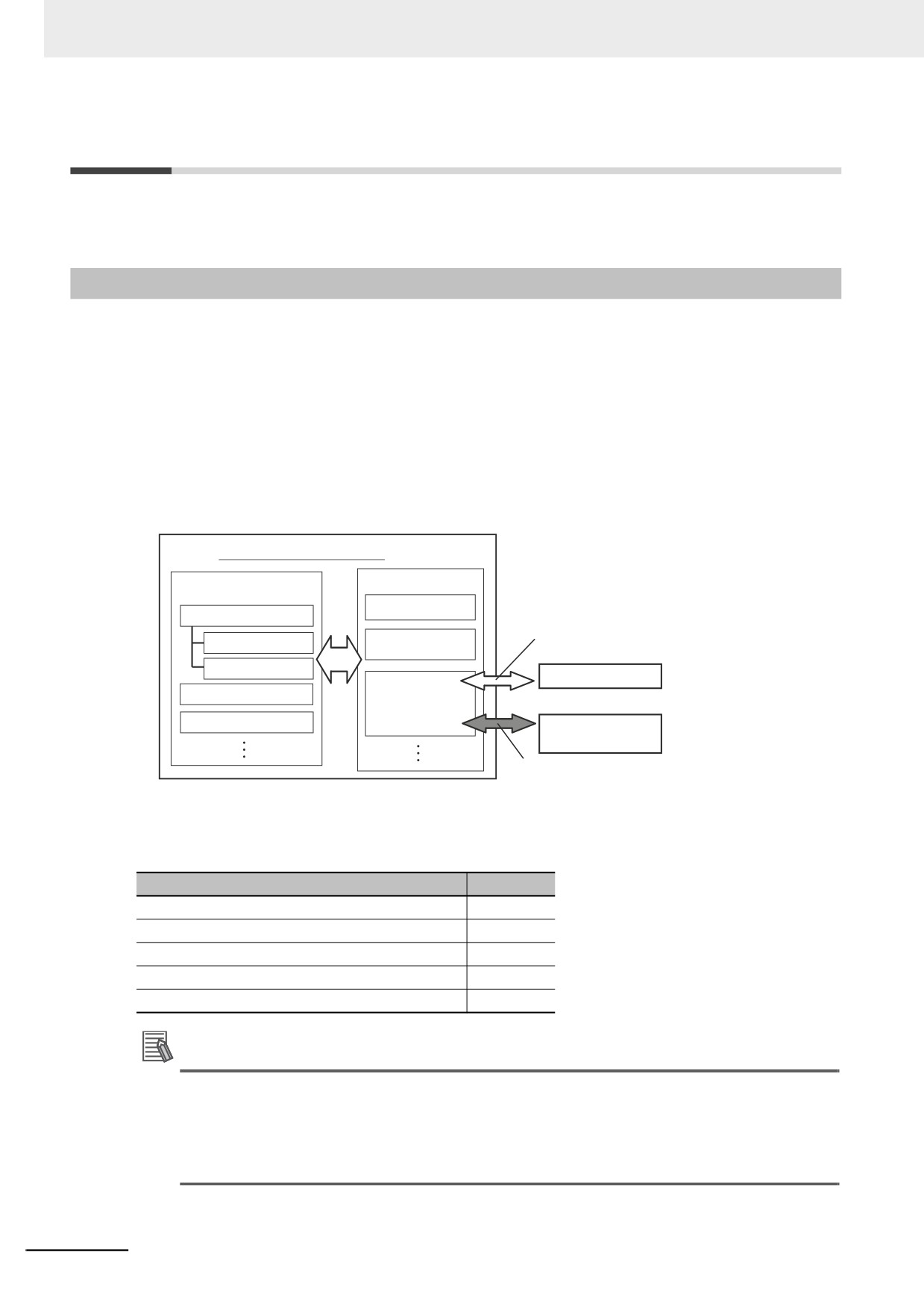
The NY-series Controller executes the user program for sequence control and motion control. It also
performs other processing, such as I/O refreshing and external communications. These processes are
performed by the software in the Controller.
The Controller also contains settings, the user program, variables, and other data. The Controller uses
this data to perform processing. Of this data, variables are used to access the Controller and I/O, and
for external communications.
The internal software and the use of variables for I/O access enable the Controller to execute both
sequence control and motion control.
NY-series Controller
Software
Data
Settings
User program execution
Accessing I/O
Sequence control
User program
Motion control
EtherCAT slaves
Variables
I/O refreshing
External communications
Other Controllers,
host computers, etc.
External communications
This section describes the following items to provide you with a basic understanding of how the Control-
ler performs sequence control and motion control.
Item
Reference
Software
P.2-4
Accessing I/O
P.2-10
Sequence control and motion control
P.2-16
Overview of Controller data
P.2-21
Operation for Controller status
P.2-22
Additional Information
• Refer to the NY-series Industrial Panel PC / Industrial Box PC Built-in EtherNet/IP Port User's
Manual (Cat. No. W563) for details on the use of variables for external communications.
• Variables in the NY-series Controller can be accessed from Windows. Refer to the NY-series
Industrial Panel PC / Industrial Box PC Setup User's Manual (Cat. No. W568) for information
on accessing.
2-2
2 NY-series Controller Operation
2-1-2
Overview of Operation According to NY-series Controller Status
The status of the NY-series Controller changes when an error occurs or when you change the operating
mode. Changes in the status of the NY-series Controller affect user program execution, I/O refreshing,
and the processing of external communications.
The Controller operation according to the status of the Controller is described in 2-6 Operation for Con-
troller Status.
2
2-3
2 NY-series Controller Operation
2-2
Software
This section describes the software configuration of the NY-series Controller functions, and how the
software components operate.
2-2-1
Software Configuration
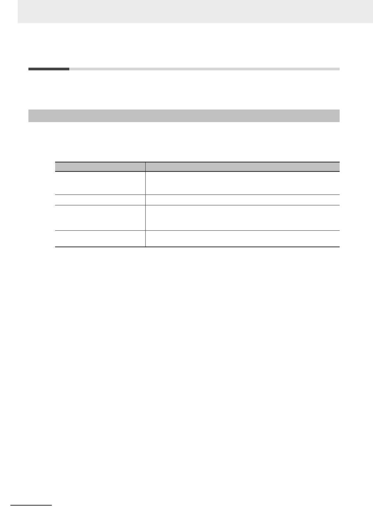
The software in the Controller is divided into four modules. These functional units are called function
modules.
The function modules and the processing that they perform are described in the following table.
Function module name
Processing
PLC Function Module
Performs the following services: task scheduling, commands for other func-
tion modules, event logging, execution of the user program, Virtual SD
Memory Card services, and data trace processing.
Motion Control Function Module
Performs motion control processing.*1
EtherCAT Master Function Mod-
Performs communications with EtherCAT slaves as the EtherCAT master,
ule
including I/O refreshing*2 for the EtherCAT slaves, EtherCAT message com-
munications*3, etc.
EtherNet/IP Function Module
Performs processing for EtherNet/IP communications, including tag data link
processing, built-in EtherNet/IP port servicing, etc.
*1
This function module executes motion processing based on target values (such as the position or velocity tar-
get value) from the motion control instructions. It outputs command values, controls status, and obtains infor-
mation through the EtherCAT Master Function Module.
*2
I/O refreshing for EtherCAT slaves is performed by using process data communications (also called PDO com-
munications). In PDO communications, the master and slaves exchange data cyclically at regular intervals.
*3
This module communicates with the EtherCAT slaves as the EtherCAT master.
2-4
2 NY-series Controller Operation
2-2-2
Operation of Software
The software in the Controller performs the following four processes. Which process is performed
depends on the status of the Controller and the execution conditions of the process itself.
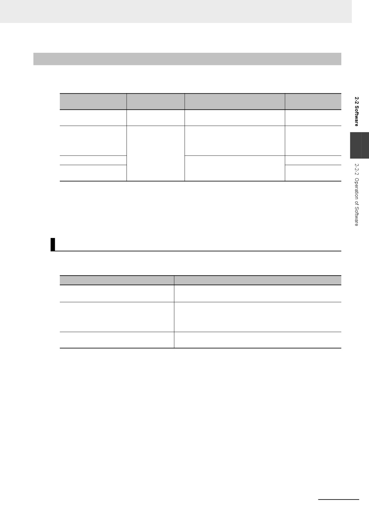
Type of Controller pro-
Processing exam-
Status of Controller
Execution conditions
cessing
ple
Initialization
Startup state
Initialization is performed only when
Self diagnosis at
the power supply is turned ON.
startup
Processing executed
Normal operation
The processing is executed within the
User program exe-
with tasks
and error states
assigned task. These tasks are exe-
cution and I/O
cuted either periodically or only once
refreshing
2
when the specified condition is met.
Tag data link service
These services are performed only
Tag data links
upon requests from the hardware or
System services
Virtual SD Memory
other external devices.
Card service
Refer to 2-6-1 Controller Status for information on the Controller status.
This section describes the operation of the processes.
Initialization
Initialization is performed only when the power supply is turned ON.
The following processing is performed for initialization.
Processing
Description
Self diagnosis at startup
Operation is monitored for the following errors: Power Supply
Error, CPU Unit Reset, and CPU Unit Watchdog Timer Error.*1
Data check
The _RetainFail (Retention Failure Flag) system-defined variable
changes to TRUE at the following time: when the values of vari-
ables for which the Retain attribute was set to retain the values
were not retained after a power interruption.
Recording Power Turned ON and Power
The Power Turned ON and Power Interrupted events are
Interrupted events
recorded.
*1
Refer to the NY-series Troubleshooting Manual (Cat. No. W564) for information on the following errors: Power
Supply Error, CPU Unit Reset, and CPU Unit Watchdog Timer Error.
2-5